Vega VEGACAP 66 User manual

Operating Instructions
Capacitive cable electrode for level
detection
VEGACAP 66
- contactless electronic switch
Document ID: 30021

2
Contents
VEGACAP 66 • - contactless electronic switch
30021-EN-160331
Contents
1 About this document
1.1 Function ........................................................................................................................... 4
1.2 Target group ..................................................................................................................... 4
1.3 Symbols used................................................................................................................... 4
2 For your safety
2.1 Authorised personnel ....................................................................................................... 5
2.2 Appropriate use................................................................................................................ 5
2.3 Warning about incorrect use............................................................................................. 5
2.4 General safety instructions............................................................................................... 5
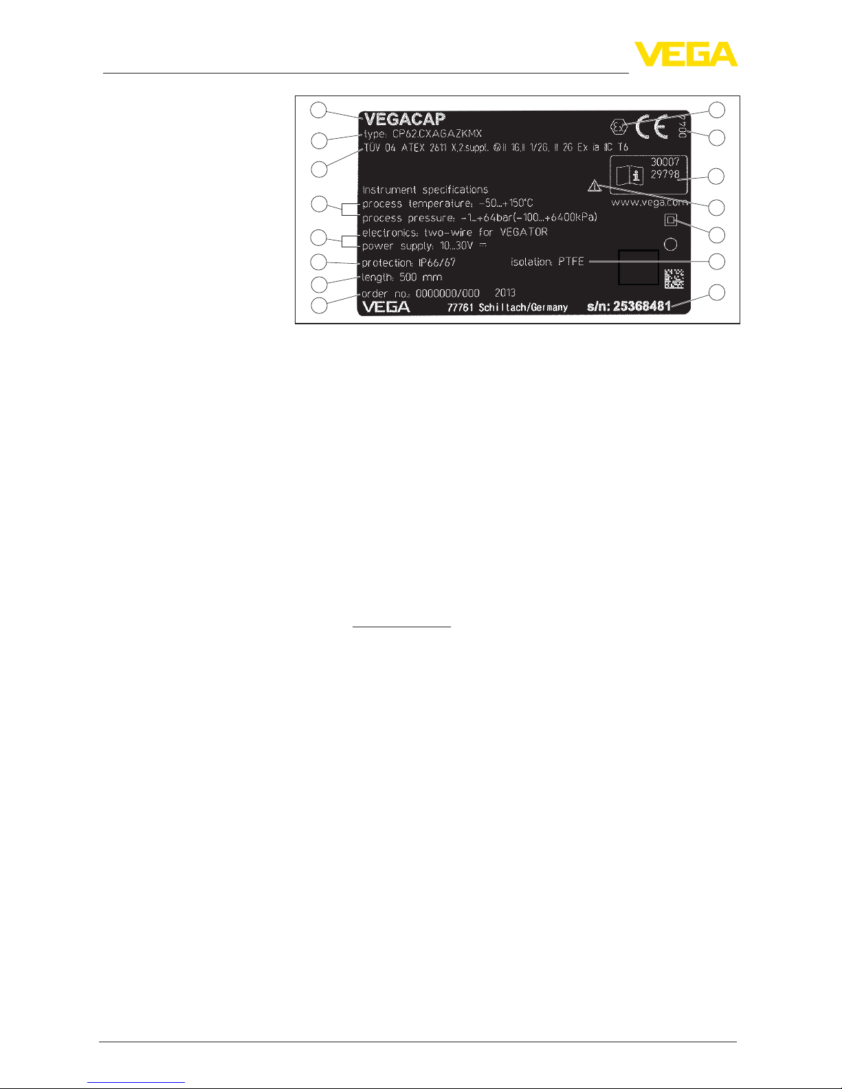
2.5 Safety label on the instrument .......................................................................................... 6
2.6 CE conformity................................................................................................................... 6
2.7 Safety instructions for Ex areas ........................................................................................ 6
2.8 Environmental instructions ............................................................................................... 6
3 Product description
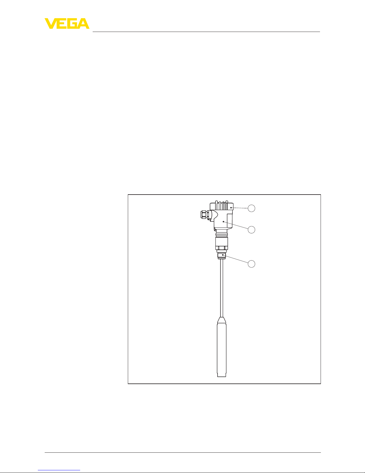
3.1 Conguration.................................................................................................................... 7
3.2 Principle of operation........................................................................................................ 8
3.3 Operation ......................................................................................................................... 9
3.4 Packaging, transport and storage..................................................................................... 9
3.5 Accessories and replacement parts ............................................................................... 10
4 Mounting
4.1 General instructions ....................................................................................................... 11
4.2 Mounting instructions ..................................................................................................... 12
5 Connecting to power supply
5.1 Preparing the connection ............................................................................................... 16
5.2 Connection procedure.................................................................................................... 16
5.3 Wiring plan, single chamber housing.............................................................................. 17
6 Setup
6.1 General information........................................................................................................ 20
6.2 Adjustment elements...................................................................................................... 20
6.3 Function table................................................................................................................. 22
7 Maintenanceandfaultrectication
7.1 Maintenance .................................................................................................................. 23
7.2 Rectify faults................................................................................................................... 23
7.3 Exchange of the electronics module............................................................................... 25
7.4 How to proceed if a repair is necessary.......................................................................... 27
8 Dismount
8.1 Dismounting steps.......................................................................................................... 28
8.2 Disposal ......................................................................................................................... 28
9 Supplement
9.1 Technical data ................................................................................................................ 29
9.2 Dimensions .................................................................................................................... 32
9.3 Industrial property rights................................................................................................. 35
9.4 Trademark ...................................................................................................................... 35

3
Contents
VEGACAP 66 • - contactless electronic switch
30021-EN-160331
Supplementary documentation
Information:
Supplementary documents appropriate to the ordered version come
withthedelivery.Youcanndthemlistedinchapter"Product descrip-
tion".
Instructions manuals for accessories and replacement parts
Tip:
ToensurereliablesetupandoperationofyourVEGACAP66,weoer
accessories and replacement parts. The corresponding documenta-
tions are:
• 30174 - Electronics module VEGACAP series 60
• 34296 - Protective cover
• 31088 - Flanges according to DIN-EN-ASME-JIS-GOST
Editing status: 2016-02-19

4
1 About this document
VEGACAP 66 • - contactless electronic switch
30021-EN-160331
1 About this document
1.1 Function
This operating instructions manual provides all the information you
need for mounting, connection and setup as well as important instruc-
tionsformaintenanceandfaultrectication.Pleasereadthisinforma-
tion before putting the instrument into operation and keep this manual
accessible in the immediate vicinity of the device.
1.2 Target group
This operating instructions manual is directed to trained specialist
personnel. The contents of this manual should be made available to
these personnel and put into practice by them.
1.3 Symbols used
Information, tip, note
This symbol indicates helpful additional information.
Caution: If this warning is ignored, faults or malfunctions can result.
Warning: If this warning is ignored, injury to persons and/or serious
damage to the instrument can result.
Danger: If this warning is ignored, serious injury to persons and/or
destruction of the instrument can result.
Ex applications
This symbol indicates special instructions for Ex applications.
SIL applications
This symbol indicates instructions for functional safety which must be
taken into account particularly for safety-relevant applications.
• List
The dot set in front indicates a list with no implied sequence.
→ Action
This arrow indicates a single action.
1 Sequence of actions
Numbers set in front indicate successive steps in a procedure.
Battery disposal
This symbol indicates special information about the disposal of bat-
teries and accumulators.

5
2 For your safety
VEGACAP 66 • - contactless electronic switch
30021-EN-160331
2 For your safety
2.1 Authorised personnel
All operations described in this operating instructions manual must
be carried out only by trained specialist personnel authorised by the
plant operator.
During work on and with the device the required personal protective
equipment must always be worn.
2.2 Appropriate use
The VEGACAP 66 is a sensor for point level detection.
Youcannddetailedinformationabouttheareaofapplicationin
chapter"Product description".
Operational reliability is ensured only if the instrument is properly
usedaccordingtothespecicationsintheoperatinginstructions
manual as well as possible supplementary instructions.
For safety and warranty reasons, any invasive work on the device
beyond that described in the operating instructions manual may be
carried out only by personnel authorised by the manufacturer. Arbi-
traryconversionsormodicationsareexplicitlyforbidden.
2.3 Warning about incorrect use
Inappropriate or incorrect use of the instrument can give rise to
application-specichazards,e.g.vesseloverllordamagetosystem
components through incorrect mounting or adjustment.
2.4 General safety instructions
This is a state-of-the-art instrument complying with all prevailing
regulations and guidelines. The instrument must only be operated in a
technicallyawlessandreliablecondition.Theoperatorisresponsible
for the trouble-free operation of the instrument.
During the entire duration of use, the user is obliged to determine the
compliance of the necessary occupational safety measures with the
current valid rules and regulations and also take note of new regula-
tions.
The safety instructions in this operating instructions manual, the na-
tional installation standards as well as the valid safety regulations and
accident prevention rules must be observed by the user.
For safety and warranty reasons, any invasive work on the device
beyond that described in the operating instructions manual may be
carried out only by personnel authorised by the manufacturer. Arbi-
traryconversionsormodicationsareexplicitlyforbidden.
The safety approval markings and safety tips on the device must also
be observed.

6
2 For your safety
VEGACAP 66 • - contactless electronic switch
30021-EN-160331
2.5 Safety label on the instrument
The safety approval markings and safety tips on the device must be
observed.
2.6 CE conformity
ThisdevicefulllsthelegalrequirementsoftheapplicableECguide-
lines.ByattachingtheCEmark,VEGAprovidesaconrmationof
successfultesting.YoucanndtheCEconformitydeclarationinthe
downloadareaof"www.vega.com".
2.7 Safety instructions for Ex areas
PleasenotetheEx-specicsafetyinformationforinstallationandop-
eration in Ex areas. These safety instructions are part of the operating
instructions manual and come with the Ex-approved instruments.
2.8 Environmental instructions
Protection of the environment is one of our most important duties.
That is why we have introduced an environment management system
with the goal of continuously improving company environmental pro-
tection.Theenvironmentmanagementsystemiscertiedaccording
to DIN EN ISO 14001.
Pleasehelpusfulllthisobligationbyobservingtheenvironmental
instructions in this manual:
• Chapter"Packaging, transport and storage"
• Chapter"Disposal"

7
3 Product description
VEGACAP 66 • - contactless electronic switch
30021-EN-160331
3 Product description
3.1 Conguration
The scope of delivery encompasses:
• VEGACAP 66 point level switch
• Documentation
– This operating instructions manual
– SafetyManual"Functional safety (SIL)"(optional)
– Supplementaryinstructionsmanual"Plug connector for level
sensors"(optional)
– Ex-specic"Safety instructions"(withExversions)
– Ifnecessary,furthercerticates
The VEGACAP 66 consists of the components:
• Processttingwithprobe
• Housing with electronics
• Housing cover, optionally available with display and adjustment
module
1
2
3
Fig. 1: VEGACAP 66 - cable version with plastic housing
1 Housing cover with integrated display and adjustment module (optional)
2 Housing with electronics
3 Processtting
Thetypelabelcontainsthemostimportantdataforidenticationand
use of the instrument:
Scope of delivery
Constituent parts
T
ype label

8
3 Product description
VEGACAP 66 • - contactless electronic switch
30021-EN-160331
2
1
11
10
13
12
14
15
9
3
6
4
5
7
8
Fig. 2: Layout of the type label (example)
1 Instrument type
2 Product code
3 Approvals
4 Process and ambient temperature, process pressure
5 Power supply and signal output, electronics
6 Protection rating
7 Probe length
8 Order number
9 Serial number of the instrument
10 Material, wetted parts
11 Symbol of the device protection class
12 Reminder to observe the instrument documentation
13 ID numbers, instrument documentation
14 NotiedauthorityforCEmarking
15 Approval directives
With the serial number, you can access the delivery data of the instru-
ment via www.vega.com,"VEGA Tools"and"serial number search".
Youcanndtheserialnumberontheinsideoftheinstrumentaswell
as on the type label on the outside.
3.2 Principle of operation
VEGACAP 66 is a point level sensor for use in non-abrasive liquids
and bulk solids.
The cable probe is fully insulated and the proven mechanical con-
structionoershighfunctionalsafety.
Probe, measured product and vessel wall form an electrical capacitor.
Thecapacitanceisinuencedbythreemainfactors.
Area of application
Functional principle

9
3 Product description
VEGACAP 66 • - contactless electronic switch
30021-EN-160331
1
2
3
Fig. 3: Functional principle - Plate capacitor
1 Distance between the electrode surfaces
2 Size of the electrode surfaces
3 Type of dielectric between the electrodes
The probe and the vessel wall are the capacitor plates. The measured
product is the dielectric. Due to the higher dielectric constant of the
product compared to air, the capacitance increases as the probe is
gradually covered.
The capacitance change is converted by the electronics module into
a switching command.
VEGACAP 66 is a compact instrument, i.e. it can be operated without
external evaluation system. The integrated electronics evaluates the
level signal and outputs a switching signal. With this switching signal,
aconnecteddevicecanbeoperateddirectly(e.g.awarningsystem,
apumpetc.).
Thedataforpowersupplyarespeciedinchapter"Technical data".
3.3 Operation
The probe can be adapted to the dielectric constant of the product
directly on the electronics module.
A switching command can be triggered when the probe is covered or
laid bare.
Ontheelectronicsmoduleyouwillndthefollowingdisplayand
adjustment elements:
• Signallampforindicationoftheswitchingcondition(green/red)
• Potentiometer for switching point adaptation
• DIL switch for measuring range selection
• DIL switch for mode adjustment
3.4 Packaging, transport and storage
Your instrument was protected by packaging during transport. Its
capacity to handle normal loads during transport is assured by a test
based on ISO 4180.
The packaging of standard instruments consists of environment-
friendly, recyclable cardboard. For special versions, PE foam or PE
Voltage supply
Packaging

10
3 Product description
VEGACAP 66 • - contactless electronic switch
30021-EN-160331
foil is also used. Dispose of the packaging material via specialised
recycling companies.
Transport must be carried out in due consideration of the notes on the
transport packaging. Nonobservance of these instructions can cause
damage to the device.
The delivery must be checked for completeness and possible transit
damage immediately at receipt. Ascertained transit damage or con-
cealed defects must be appropriately dealt with.
Up to the time of installation, the packages must be left closed and
stored according to the orientation and storage markings on the
outside.
Unless otherwise indicated, the packages must be stored only under
the following conditions:
• Not in the open
• Dry and dust free
• Not exposed to corrosive media
• Protected against solar radiation
• Avoiding mechanical shock and vibration
• Storageandtransporttemperatureseechapter"Supplement -
Technical data - Ambient conditions"
• Relative humidity 20 … 85 %
3.5 Accessories and replacement parts
The protective cover protects the sensor housing against soiling and
intense heat from solar radiation.
Youwillndadditionalinformationinthesupplementaryinstructions
manual"Protective cover"(Document-ID34296).
Screwedangesareavailableindierentversionsaccordingtothe
following standards: DIN 2501, EN 1092-1, BS 10, ASME B 16.5,
JIS B 2210-1984, GOST 12821-80.
Youcanndadditionalinformationinthesupplementaryinstructions
manual"Flanges according to DIN-EN-ASME-JIS".
Transport
Transport inspection
Storage
Storage and transport
temperature
Protective cap
Flanges

11
4 Mounting
VEGACAP 66 • - contactless electronic switch
30021-EN-160331
4 Mounting
4.1 General instructions
Make sure that all parts of the instrument coming in direct contact
with the process, especially the sensor element, process seal and
processtting,aresuitablefortheexistingprocessconditions,such
as process pressure, process temperature as well as the chemical
properties of the medium.
Youcanndthespecicationsinchapter"Technical data"andonthe
nameplate.
In general, VEGACAP 66 must be mounted vertically. The instrument
must be mounted in such a way that the probe is at the height of the
requested switching point.
Before beginning the welding work, remove the electronics module
from the sensor. By doing this, you avoid damage to the electronics
through inductive coupling.
Ground the probe before welding directly on the rod or cable.
With threaded versions, the housing must not be used to screw in the
instrument. Applying tightening forces on the housing can damage its
internal parts.
Use the hexagon for screwing in.
Usetherecommendedcables(seechapter"Connecting to power
supply")andtightenthecablegland.
You can give your instrument additional protection against moisture
penetration by leading the connection cable downward in front of the
cableentry.Rainandcondensationwatercanthusdraino.Thisap-
plies mainly to outdoor mounting as well as installation in areas where
highhumidityisexpected(e.g.throughcleaningprocesses)oron
cooled or heated vessels.
Fig. 4: Measures against moisture ingress
Theprocessttingmustbesealedifthereisgaugeorlowpressurein
the vessel. Before use, check if the seal material is resistant against
the measured product and the process temperature.
Suitability for the process
conditions
Switching point
Welding work
Handling
Moisture
Pressure/Vacuum

12
4 Mounting
VEGACAP 66 • - contactless electronic switch
30021-EN-160331
Themax.permissiblepressureisspeciedinchapter"Technical
data"oronthetypelabelofthesensor.
Metal vessel
Make sure that the mechanical connection of the probe to the vessel
iselectricallyconductivetoensuresucientgrounding.
Use conductive seals, such as those made of copper or lead, etc.
Insulatingmeasures,suchascoveringthethreadwithTeontape,
can interrupt the necessary electrical connection with metal vessels.
For this reason, ground the probe on the vessel or use a conductive
seal material.
Non-conductive vessels
In non-conductive vessels, e.g. plastic tanks, the second pole of the
capacitor must be provided separately.
Ifcondensateformsonthevesseltop,therun-oliquidcancause
bridging and hence faulty switchings.
For this reason, use a screening tube . The length of the screening
tubedependsontheamountofcondensateandthedrain-obehav-
iour of the product.
Metric threads
In the case of instrument housings with metric thread, the cable
glands are screwed in at the factory. They are sealed with plastic
plugs as transport protection.
You have to remove these plugs before electrical connection.
NPT thread
In the case of instrument housings with self-sealing NPT threads, it is
not possible to have the cable entries screwed in at the factory. The
free openings for the cable glands are therefore covered with red dust
protection caps as transport protection.
Prior to setup you have to replace these protective caps with ap-
proved cable glands or close the openings with suitable blind plugs.
4.2 Mounting instructions
Duetotheeectsofagitators,equipmentvibrationorsimilar,thelevel
switch can be subjected to strong lateral forces. For this reason, do
not use an overly long electrode for VEGACAP 66, but check if you
canmountashortlevelswitchonthesideofthevesselinhorizontal
position.
Iftheinstrumentismountedinthellingstream,unwantedfalse
measurement signals can be generated. For this reason, mount the
instrument at a position in the vessel where no disturbances, e.g. from
llingopenings,agitators,etc.,canoccur.
This applies particularly to instrument versions with a longer probe.
Vessel material
Condensation
Cable entries - NPT
thread
Cable glands
Agitatorsanduidization
Inowingmedium

13
4 Mounting
VEGACAP 66 • - contactless electronic switch
30021-EN-160331
Fig.5:Inowingmedium
The probe should protrude into the vessel to avoid buildup. For that
reason,avoidusingmountingbossesforangesandscrewedttings.
This applies particularly to use with adhesive products.
In silos with bulk solids, material cones can form which change the
switching point. Please keep this in mind when installing the sensor
in the vessel. We recommend selecting an installation location where
the probe detects the average value of the material cone.
The probe must be mounted in a way that takes the arrangement of
thellingandemptyingaperturesintoaccount.
To compensate measurement errors caused by the material cone in
cylindrical vessels, the sensor must be mounted at a distance of d/6
from the vessel wall.
Socket
Material cone

14
4 Mounting
VEGACAP 66 • - contactless electronic switch
30021-EN-160331
dd
d
6
d
6
Fig. 6: Filling and emptying centred
d
d
6
1
2
3
Fig. 7: Filling in the centre, emptying laterally
1 VEGACAP 66
2 Discharge opening
3 Filling opening

15
4 Mounting
VEGACAP 66 • - contactless electronic switch
30021-EN-160331
Make sure that the max. permissible tensile load of the suspension
cable is not exceeded.The danger of this happening exists particu-
larly with very heavy solids and large meas. lengths. The max. permis-
sibleloadisstatedinchapter"Technical data".
Tensile load

16
5 Connecting to power supply
VEGACAP 66 • - contactless electronic switch
30021-EN-160331
5 Connecting to power supply
5.1 Preparing the connection
Always keep in mind the following safety instructions:
Warning:
Connect only in the complete absence of line voltage.
• The electrical connection must only be carried out by trained
personnel authorised by the plant operator.
• Alwaysswitchopowersupply,beforeconnectingordisconnect-
ing the instrument.
Note:
Install a separating facility for the instrument which is easy to access.
Theseparatingfacilitymustbemarkedfortheinstrument(IEC/
EN61010).
Connect mains voltage according to the connection diagrams. Take
note of the general installation regulations. The electronics module
CP60C is designed in protection class I. To maintain this protection
class, it is absolutely necessary that the ground conductor be con-
nected to the internal ground conductor terminal. Take note of the
corresponding installation regulations for Ex applications.
Thedataforpowersupplyarespeciedinchapter"Technical data".
The instrument is connected with standard three-wire cable without
screen. If electromagnetic interference is expected which is above the
test values of EN 61326 for industrial areas, screened cable should
be used.
Use cable with round cross-section. A cable outer diameter of
5…9mm(0.2…0.35in)ensuresthesealeectofthecablegland.
Ifyouareusingcablewithadierentdiameterorcross-section,
exchange the seal or use a suitable cable gland.
5.2 Connection procedure
With Ex instruments, the housing cover may only be opened if there is
no explosive atmosphere present.
Proceed as follows:
1. Unscrew the housing lid
2. Loosen compression nut of the cable gland and remove blind
plug
3. Removeapprox.10cm(4in)ofthecablemantle,stripapprox.
1cm(0.4in)ofinsulationfromtheendsoftheindividualwires
4. Insert the cable into the sensor through the cable entry
5. Lifttheopeningleversoftheterminalswithascrewdriver(see
followingillustration)
6. Insert the wire ends into the open terminals according to the wir-
ing plan
Note safety instructions
Voltage supply
Connection cable

17
5 Connecting to power supply
VEGACAP 66 • - contactless electronic switch
30021-EN-160331
7. Press down the opening levers of the terminals, you will hear the
terminal spring closing
8. Check the hold of the wires in the terminals by lightly pulling on
them
9. Tighten the compression nut of the cable entry gland. The seal
ring must completely encircle the cable
10. If necessary, carry out a fresh adjustment
11. Screw the housing lid back on
Theelectricalconnectionisnished.
Fig. 8: Connection steps 5 and 6
5.3 Wiring plan, single chamber housing
1
4
44
2 3
Fig. 9: Material versions, single chamber housing
1 Plastic (not with dust-Ex)
2 Aluminium
3 Stainless steel
4 Filter element for air pressure compensation
Housing overview

18
5 Connecting to power supply
VEGACAP 66 • - contactless electronic switch
30021-EN-160331
4
5
6
3
2
1
Fig. 10: Electronics and terminal compartment
1 Potentiometer for switching point adaptation
2 DIL switch for measuring range selection
3 DIL switch for mode adjustment
4 Ground terminal
5 Connection terminals
6 Control lamp
We recommend connecting VEGACAP 66 in such a way that the
switching circuit is open when there is a level signal, line break or
failure(safestate).
The contactless electronic switch is always shown in non-operative
condition.
Warning:
The instrument must not be operated without an intermediately
connected load, because the electronics would be destroyed if con-
nected directly to the mains. It is not suitable for connection to low
voltage PLC inputs.
Examples for typical applications:
• Loadresistanceat24VDC:88…1800Ω
• Rated power, relay 253 V AC: > 2.5 VA
• Rated power, relay 24 V AC: > 0.5 VA
For direct control of relays, contactors, magnet valves, warning lights,
horns etc.
Domestic current is temporarily lowered below 1 mA after switching
otheloadsothatcontactors,whoseholdingcurrentislowerthan
the constant domestic current of the electronics, are reliably switched
o.
Electronics and terminal
compartment
Wiring plan

19
5 Connecting to power supply
VEGACAP 66 • - contactless electronic switch
30021-EN-160331
WhenVEGACAP66isusedaspartofanoverllprotectionsystem
according to WHG, also note the regulations of the general type ap-
proval.
1
Fig. 11: Wiring plan
1 Voltage supply

20
6 Setup
VEGACAP 66 • - contactless electronic switch
30021-EN-160331
6 Setup
6.1 General information
Theguresinbracketsrefertothefollowingillustrations.
Ontheelectronicsmoduleyouwillndthefollowingdisplayand
adjustment elements:
• Potentiometer for switching point adaptation
• DIL switch for measuring range selection
• DIL switch for mode adjustment - min./max.
• Control lamp
Note:
Asarule,alwayssetthemodewiththemodeswitch(3)beforestart-
ing setup VEGACAP 66. The switching output will change if you set
themodeswitch(3)afterwards.Thiscouldpossiblytriggerothercon-
nected instruments or devices.
6.2 Adjustment elements
4
5
6
3
2
1
Fig. 12: Oscillator - Contactless electronic switch
1 Potentiometer for switching point adaptation
2 DIL switch for measuring range selection (with compensation button)
3 DIL switch for mode adjustment
4 Ground terminal
5 Connection terminals
6 Control lamp
The switching status of the electronics can be checked with closed
housing(onlyplastichousing),see"Function table".
Note:
Screw the housing cover tightly up to the thread stop so that the
inspectionglassisabovethecontrollamp(LED).
Function/Conguration
Other manuals for VEGACAP 66
2
This manual suits for next models
1
Table of contents
Other Vega Switch manuals

Vega
Vega VEGASWING 63 User manual

Vega
Vega VEGACAP 67 User manual

Vega
Vega VEGACAP 65 User manual

Vega
Vega VEGAVIB 63 User manual

Vega
Vega VEGASWING 51 User manual

Vega
Vega VEGASWING 63 User manual

Vega
Vega VEGASWING 66 User guide

Vega
Vega VEGASWING 66 User manual

Vega
Vega VEGAWAVE 63 User manual

Vega
Vega VEGASWING 51 User manual

Vega
Vega VEGACAP 64 User manual

Vega
Vega VEGAPOINT 11 User manual

Vega
Vega VEGASWING 63 User manual

Vega
Vega VEGASWING 51 User manual

Vega
Vega VEGAWAVE 62 User manual

Vega
Vega VEGAWAVE 63 User manual

Vega
Vega VEGAKON 61 User manual

Vega
Vega VEGAWAVE 61 User manual

Vega
Vega VEGAVIB 62 User manual

Vega
Vega VEGASEL 643 User manual