Vega VEGASWING 51 User manual

Operating Instructions
VEGASWING 51
-contactless electronic switch
Vibration

Contents
1About this document
1.1Function ................................. 3
1.2Target group .............................. 3
1.3Symbolism used ........................... 3
2For your safety
2.1Authorised personnel ........................ 4
2.2Appropriate use ............................ 4
2.3Warning about misuse ....................... 4
2.4General safety instructions . . . . . . . . . . . . . . . . . . . . 4
2.5Safety approval markings and safety tips . . . . . . . . . 5
2.6CE conformity ............................. 5
2.7Environmental instructions . . . . . . . . . . . . . . . . . . . . 5
3Product description
3.1Configuration .............................. 6
3.2Principle of operation ........................ 7
3.3Operation ................................ 7
3.4Storage and transport ....................... 8
4Mounting
4.1General instructions ......................... 9
4.2Mounting instructions ........................ 11
5Connecting to power supply
5.1Preparing the connection ..................... 13
5.2Wiring plan ............................... 14
6Set up
6.1Indication of the switching status ............... 18
6.2Function test .............................. 18
6.3Functional chart ............................ 19
7Maintenance and fault rectification
7.1Maintenance .............................. 20
7.2Remove interferences ....................... 20
7.3Exchange electronics ........................ 21
7.4Instrument repair ........................... 22
8Dismounting
8.1Dismounting steps .......................... 24
8.2Disposal ................................. 24
9Supplement
9.1Technical data ............................ 25
9.2Dimensions ............................... 29
9.3Industrial property rights . . . . . . . . . . . . . . . . . . . . . . 32
9.4Trademark ............................... 32
2VEGASWING 51 • - contactless electronic switch
Contents
30212-EN-081121

1About this document
1.1Function
This operating instructions manual provides all the information you
need for mounting,connection and setup as well as important
instructions for maintenance and fault rectification.Please read this
information before putting the instrument into operation and keep this
manual accessible in the immediate vicinity of the device.
1.2Target group
This operating instructions manual is directed to trained personnel.
The contents of this manual should be made available to these
personnel and put into practice by them.
1.3Symbolism used
Information,tip,note
This symbol indicates helpful additional information.
Caution:If this warning is ignored,faults or malfunctions can
result.
Warning:If this warning is ignored,injury to persons and/or serious
damage to the instrument can result.
Danger:If this warning is ignored,serious injury to persons and/or
destruction of the instrument can result.
Ex applications
This symbol indicates special instructions for Ex applications.
lList
The dot set in front indicates a list with no implied sequence.
àAction
This arrow indicates a single action.
1Sequence
Numbers set in front indicate successive steps in a procedure.
VEGASWING 51 • - contactless electronic switch 3
1About this document
30212-EN-081121

2For your safety
2.1Authorised personnel
All operations described in this operating instructions manual must be
carried out only by trained specialist personnel authorised by the plant
operator.
During work on and with the device the required personal protection
equipment must always be worn.
2.2Appropriate use
VEGASWING 51 is a sensor for level detection.
You can find detailed information on the application range in chapter
"Product description".
Operational reliability is ensured only if the instrument is properly used
according to the specifications in the operating instructions manual as
well as possible supplementary instructions.
For safety and warranty reasons,any invasive work on the device
beyond that described in the operating instructions manual may be
carried out only by personnel authorised by the manufacturer.Arbitrary
conversions or modifications are explicitly forbidden.
2.3Warning about misuse
Inappropriate or incorrect use of the instrument can give rise to
application-specific hazards,e.g.vessel overfill or damage to system
components through incorrect mounting or adjustment.
2.4General safety instructions
This is a high-tech instrument requiring the strict observance of
standard regulations and guidelines.The user must take note of the
safety instructions in this operating instructions manual,the country-
specific installation standards as well as all prevailing safety
regulations and accident prevention rules.
The instrument must only be operated in a technically flawless and
reliable condition.The operator is responsible for trouble-free
operation of the instrument.
During the entire duration of use,the user is obliged to determine the
compliance of the required occupational safety measures with the
current valid rules and regulations and also take note of new
regulations.
4VEGASWING 51 • - contactless electronic switch
2For your safety
30212-EN-081121

2.5Safety approval markings and safety tips
The safety approval markings and safety tips on the device must be
observed.
2.6CE conformity
This device fulfills the legal requirements of the applicable EC
guidelines.By attaching the CE mark,VEGA provides a confirmation
of successful testing.You can find the CE conformity declaration in the
download area of www.vega.com.
2.7Environmental instructions
Protection of the environment is one of our most important duties.That
is why we have introduced an environment management system with
the goal of continuously improving company environmental protection.
The environment management system is certified according to DIN
EN ISO 14001.
Please help us fulfil this obligation by observing the environmental
instructions in this manual:
lChapter "Packaging,transport and storage"
lChapter "Disposal"
VEGASWING 51 • - contactless electronic switch 5
2For your safety
30212-EN-081121

3Product description
3.1Configuration
The scope of delivery encompasses:
lVEGASWING 51 point level sensor
lTest magnet
lDocumentation
-this operating instructions manual
-if necessary,certificates
VEGASWING 51 consists of the following components:
lHousing with electronics
lprocess fitting with tuning fork
Fig.1:VEGASWING 51
The type label contains the most important data for identification and
use of the instrument:
lArticle number
lSerial number
lTechnical data
lArticle numbers documentation
With the serial number,you can access the delivery data of the
instrument via www.vega.com,"VEGA Tools"and "serial number
search".In addition to the type label outside,you can also find the
serial number on the inside of the instrument.
Scope of delivery
Components
Type label
6VEGASWING 51 • - contactless electronic switch
3Product description
30212-EN-081121

3.2Principle of operation
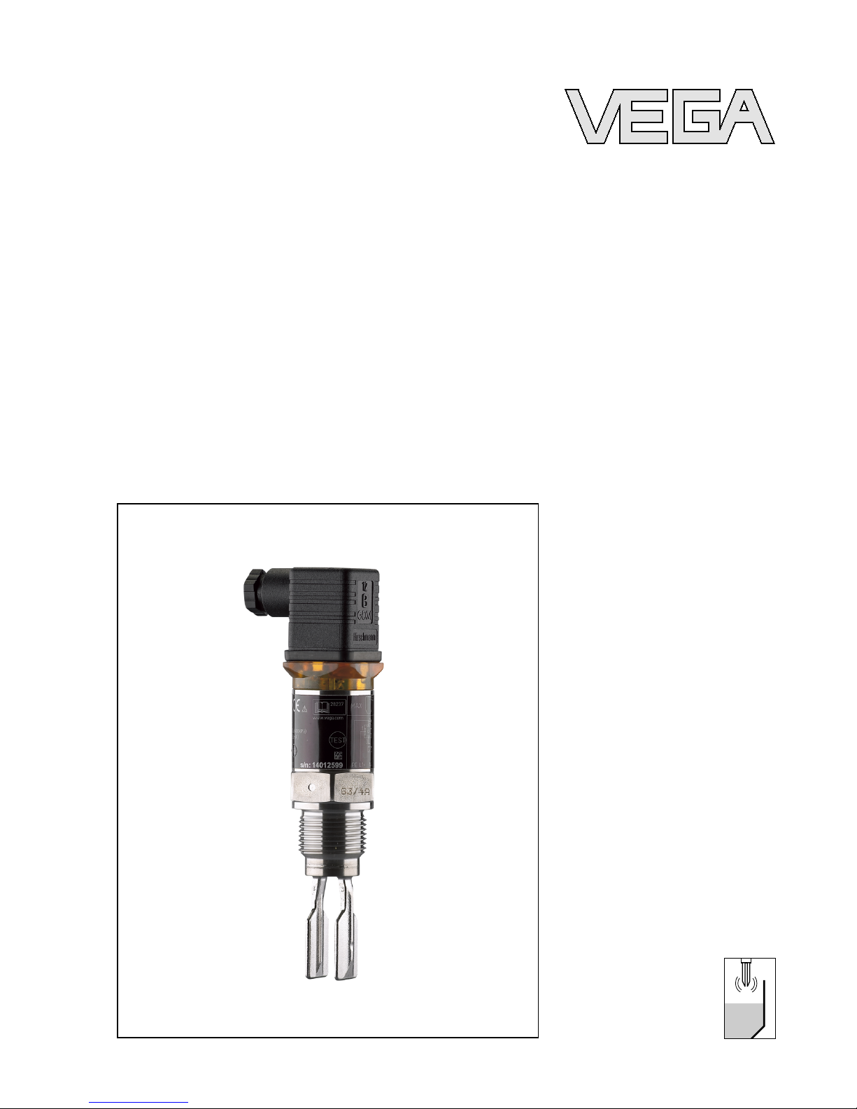
VEGASWING 51 is a point level sensor with tuning fork for level
detection.
It is designed for industrial use in all areas of process technology and
can be used in liquids.
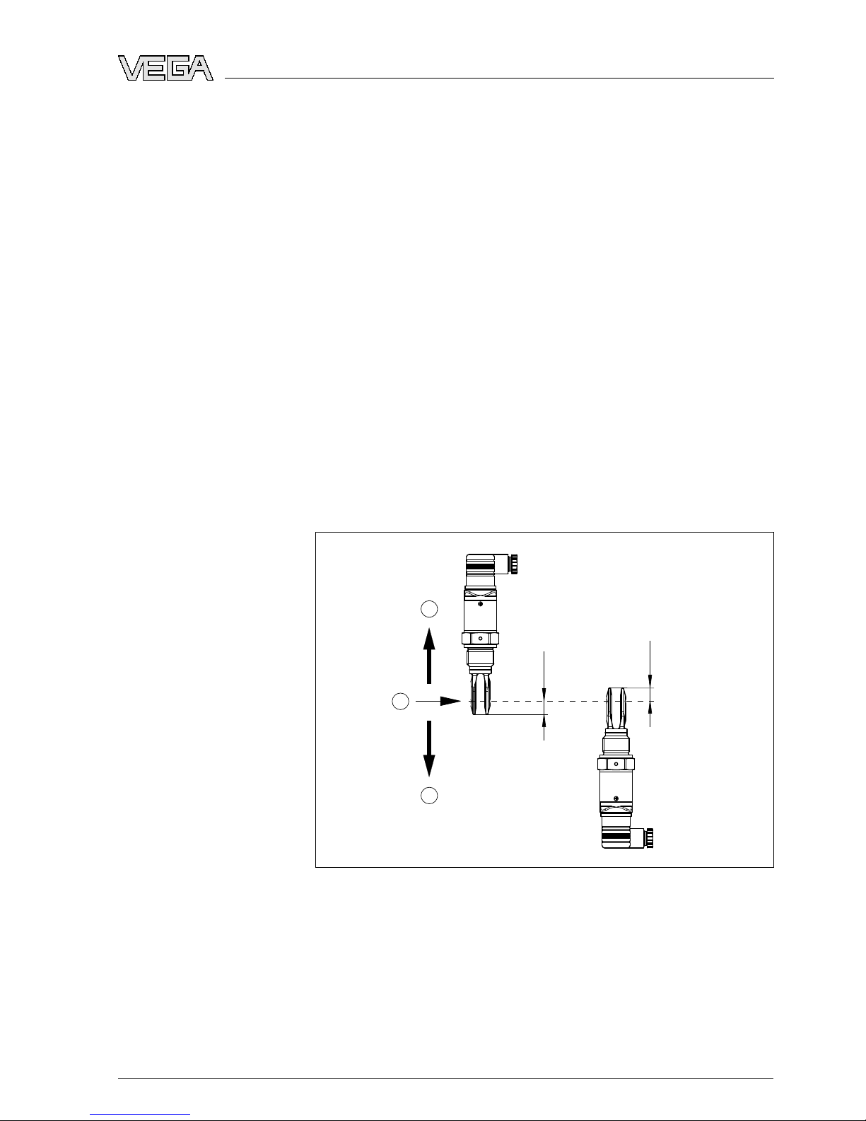
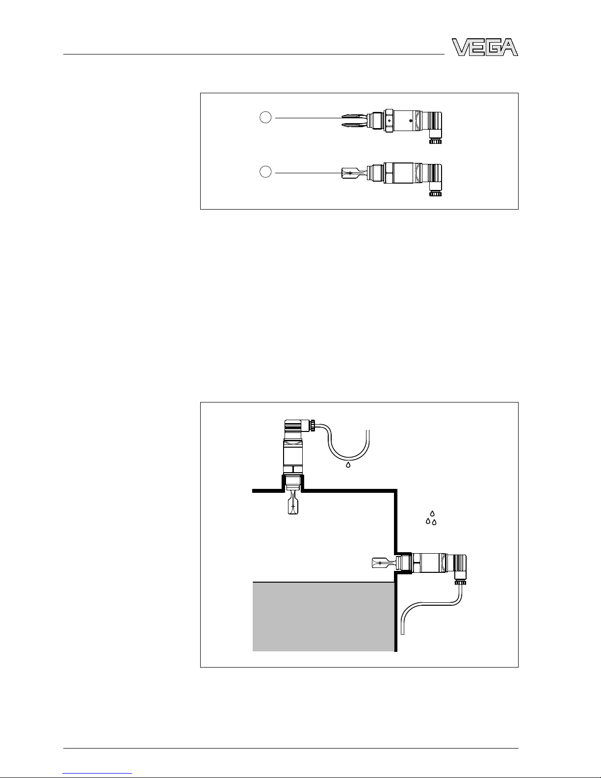
Typical applications are overfill and dry run protection.With a tuning
fork of only 40 mm length,VEGASWING 51 can be also mounted,e.g.
in pipelines from DN 32.The small tuning fork allows use in vessels,
tanks and pipes.Thanks to its simple and robust measuring system,
VEGASWING 51 is virtually unaffected by the chemical and physical
properties of the liquid.
It functions even under difficult conditions such as turbulence,air
bubbles,foam generation,buildup,strong external vibration or
changing products.
Fault monitoring
The electronics module of VEGASWING 51 continuously monitors via
frequency evaluation the following criteria:
lStrong corrosion or damage on the tuning fork
lloss of vibration
lLine break to the piezo drive
If a malfunction is detected or in case of power failure,the electronics
takes on a defined switching condition,i.e.the contactless electronic
switch opens (safe condition).
The tuning fork is piezoelectrically energised and vibrates at its
mechanical resonance frequency of approx.1200 Hz.The piezos are
fixed mechanically and are hence not subject to temperature shock
limitations.The frequency changes when the tuning fork is covered by
the medium.This change is detected by the integrated electronics
module and converted into a switching command.
VEGASWING 51 is a compact instrument,i.e.it can be operated
without external evaluation system.The integrated electronics
evaluates the level signal and outputs a switching signal.With this
switching signal,a connected device can be operated directly (e.g.a
warning system,aPLC,a pump etc.).
The data for power supply are specified in chapter "Technical data".
3.3Operation
The switching status of VEGASWING 51 can be checked with closed
housing (signal lamp). Products with a density >0.7g/cm³(0.025 lbs/
in³)can be detected.
Application area
Functional principle
Power supply
VEGASWING 51 • - contactless electronic switch 7
3Product description
30212-EN-081121

3.4Storage and transport
Your instrument was protected by packaging during transport.Its
capacity to handle normal loads during transport is assured by a test
according to DIN EN 24180.
The packaging of standard instruments consists of environment-
friendly,recyclable cardboard.For special versions,PE foam or PE foil
is also used.Dispose of the packaging material via specialised
recycling companies.
Transport must be carried out under consideration of the notes on the
transport packaging.Nonobservance of these instructions can cause
damage to the device.
The delivery must be checked for completeness and possible transit
damage immediately at receipt.Ascertained transit damage or
concealed defects must be appropriately dealt with.
Up to the time of installation,the packages must be left closed and
stored according to the orientation and storage markings on the
outside.
Unless otherwise indicated,the packages must be stored only under
the following conditions:
lNot in the open
lDry and dust free
lNot exposed to corrosive media
lProtected against solar radiation
lAvoiding mechanical shock and vibration
lStorage and transport temperature see chapter "Supplement -
Technical data -Ambient conditions"
lRelative humidity 20 …85 %
Packaging
Transport
Transport inspection
Storage
Storage and transport
temperature
8VEGASWING 51 • - contactless electronic switch
3Product description
30212-EN-081121

4Mounting
4.1General instructions
Make sure that all parts of the instrument in contact with the measured
product,especially the sensor element,process seal and process
fitting,are suitable for the existing process conditions such as process
pressure,process temperature as well as the chemical properties of
the medium.
You can find the specifications in chapter "Technical data"in the or on
the type label.
In general,VEGASWING 51 can be installed in any position.The
instrument simply has be mounted in such a way that the tuning fork is
at the height of the desired switching point.
The tuning fork has lateral marking (notches), marking the switching
point with vertical mounting.The switching point refers to water (1g/
cm³/0.036 lbs/in³). When mounting VEGASWING 51,make sure that
this marking is at the height of the requested switching point.Keep in
mind that the switching point of the instrument is shifted if the medium
has a density other than water.
2
3
1
13mm
(33/64")
13mm
(33/64")
Fig.2:Vertical mounting
1Switching point approx.13 mm (0.51 in)
2Switching point with lower density
3Switching point with higher density
Suitability for process
conditions
Switching point
VEGASWING 51 • - contactless electronic switch 9
4Mounting
30212-EN-081121

1
2
Fig.3:Horizontal mounting
1Switching point
2Switching point (recommended mounting position,particularly for adhesive
products)
Use the recommended cables (see chapter "Connecting to power
supply")and tighten the cable gland.
You can give your VEGASWING 51 additional protection against
moisture penetration by leading the connection cable downward in
front of the cable entry.Rain and condensation water can thus drain
off.This applies mainly to outdoor mounting as well as installation in
areas where high humidity is expected (e.g.through cleaning
processes)or on cooled or heated vessels.
Fig.4:Measures against moisture penetration
Do not hold VEGASWING 51 on the tuning fork.
Moisture
Transport
10 VEGASWING 51 • - contactless electronic switch
4Mounting
30212-EN-081121

The process fitting must be sealed if there is gauge or low pressure in
the vessel.Before use,check if the seal material is resistant against
the measured product and the process temperature.
The max.permissible pressure is specified in chapter "Technical data"
or on the type label of the sensor.
The vibrating level switch is a measuring instrument and must be
treated accordingly.Bending the vibrating element will destroy the
instrument.
Warning:
The housing must not be used to screw the instrument in!Applying
tightening force can damage internal parts of the housing.
Use the hexagon above the thread for screwing in.
4.2Mounting instructions
For welded socket with O-ring in front and welding marking.
VEGASWING 51 has a defined thread outlet.This means that every
VEGASWING 51 is in the same position after being screwed in.
Remove therefore the supplied flat seal from the thread of
VEGASWING 51.This flat seal is not required when using a welded
socket with front-flush seal.
Before welding,unscrew VEGASWING 51 and remove the rubber ring
from the welded socket.
The welded socket has a marking (notch). For horizontal mounting,
weld the socket with the notch facing upward or downward;in
pipelines (DN 32 to DN 50)aligned with the direction of flow.
1
Fig.5:Marking on the welded socket
1Marking
In case of horizontal mounting in adhesive and viscous products,the
surfaces of the tuning fork should be vertical in order to reduce buildup
on the tuning fork.The position of the tuning fork is indicated by a
Pressure/Vacuum
Handling
Welded socket
Adhesive products
VEGASWING 51 • - contactless electronic switch 11
4Mounting
30212-EN-081121

marking on the hexagon of VEGASWING 51.With this,you can check
the position of the tuning fork when screwing it in.When the hexagon
touches the seal,the thread can still be turned by approx.half a turn.
This is sufficient to reach the recommended installation position.
In adhesive and viscous products,the surfaces of the tuning fork
should protrude into the vessel to avoid buildup.Therefore sockets for
flanges and mountings bosses should not exceed a certain length.
30mm
(1 3/16")
Fig.6:Adhesive products
IfVEGASWING 51 is mounted in the filling stream,unwanted false
measurement signals can be generated.For this reason,mount
VEGASWING 51 at a position in the vessel where no disturbances,e.
g.from filling openings,agitators,etc., can occur.
To minimise flow resistance caused by the tuning fork,VEGASWING
51 should be mounted in such a way that the surfaces of the blades
are parallel to the product movement.
Inflowing medium
Flows
12 VEGASWING 51 • - contactless electronic switch
4Mounting
30212-EN-081121

5Connecting to power supply
5.1Preparing the connection
Always keep in mind the following safety instructions:
lConnect only in the complete absence of line voltage
The instrument is connected with standard two-wire cable without
screen.If electromagnetic interference is expected which is above the
test values of EN 61326 for industrial areas,screened cable should be
used.
Use cable with round cross section.Depending on the plug
connection,you have to select the outer diameter of the cable
respectively so that the seal effect of the cable gland is ensured.
lValve plug DIN 43650,ø4.5…7mm
lValve plug DIN 43650 with IDC method of termination,ø5.5…8mm
Use cable with a round wire cross section and tighten the cable gland.
When mounting outdoors,on cooled vessels or in humid areas,in
which cleaning is carried out e.g.with steam or high pressure,it is
particularly important to seal the cable gland.
Note safety instructions
Selecting connection
cable
Cable glands
VEGASWING 51 • - contactless electronic switch 13
5Connecting to power supply
30212-EN-081121

5.2Wiring plan
1 2
Fig.7:Overview of the connection versions
1Valve plug DIN 43650
2Valve plug DIN 43650 with IDC method of termination
Valve plug DIN 43650
For this plug version,standard cable with round wire cross-section can
be used.Cable diameter 4.5…7mm,protection IP 65.
Housing overview
Plug versions
14 VEGASWING 51 • - contactless electronic switch
5Connecting to power supply
30212-EN-081121

1
4
5
6
7
8
9
10
2 3
Fig.8:Connection,valve plug DIN 43650
1Pressure screw
2Pressure disc
3Seal ring
4Fixing screw
5Seal washer
6Plug housing
7Plug insert
8Profile seal
9Control lamp
10 VEGASWING 51
Valve plug DIN 43650 with IDC method of termination
For this plug version you can use standard cable with round wire
cross-section.The inner cables must not be dismantled.The plug
connects the cables automatically when screwing in.Cable diameter
5.5…8mm,protection IP 67.
VEGASWING 51 • - contactless electronic switch 15
5Connecting to power supply
30212-EN-081121

1 2 3 4
5
Fig.9:Connection,valve plug DIN 43650 with IDC method of termination
1Compression nut
2Cable
3Seal ring
4Terminal insert
5Plug housing
We recommend connecting VEGASWING 51 in such a way that the
switching circuit is open when there is a level signal,line break or
failure (safe condition).
Warning:
The instrument must not be operated without an intermediately
connected load,because the electronics would be destroyed if
connected directly to the mains.It is not suitable for connection to low
voltage PLC inputs.
For direct control of relays,contactors,magnet valves,warning lights,
horns etc.
Domestic current is temporarily lowered below 1mAafter switching off
the load so that contactors,whose holding current is lower than the
constant domestic current of the electronics (3mA), are reliably
switched off.
Contactless electronic
switch
16 VEGASWING 51 • - contactless electronic switch
5Connecting to power supply
30212-EN-081121

RL RL
3
2
1
3
2
1
N- L1+L1+ N-
Max. Min.
PE PE
Fig.10:Wiring plan,contactless electronic switch with valve plug DIN 43650
PE Protective ground
RL Load resistance (contactor,relay,etc.)
VEGASWING 51 • - contactless electronic switch 17
5Connecting to power supply
30212-EN-081121

6Set up
6.1Indication of the switching status
The switching status of the electronics can be checked via the signal
lamp integrated in the upper part of the housing.
6.2Function test
VEGASWING 51 has an integrated test switch which can be activated
magnetically.Proceed as follows to test the instrument:
àHold the test magnet (accessory)to the magnet symbol on the
instrument housing
Fig.11:Function test
The test magnet changes the current switching condition of the
instrument.You can check the change on the signal lamp.Please note
that the connected instruments are activated during the test.
IfVEGASWING 51 does not switch over after several tests with the
test magnet,you have to check the plug connection and the
connection cable and test the instrument again.If there is no switching
function,the electronics will be defective.In this case you have to
exchange the electronics or return the instrument to our repair
department.
Caution:
It is absolutely necessary that you remove the test magnet after the
test from the instrument housing.
18 VEGASWING 51 • - contactless electronic switch
6Set up
30212-EN-081121

6.3Functional chart
The following chart provides an overview of the switching conditions
depending on the adjusted mode and level.
Level Switching status Control lamp
Mode max.Switch closed Green
Mode max.Switch open Red
Mode min.Switch closed Green
Mode min.Switch open Red
Failure any Switch open flashes red
VEGASWING 51 • - contactless electronic switch 19
6Set up
30212-EN-081121

7Maintenance and fault rectification
7.1Maintenance
When used in the correct way,no special maintenance is required in
normal operation.
7.2Remove interferences
The operator of the system is responsible for taken suitable measures
to remove interferences.
Amaximum of reliability is ensured.Nevertheless,faults can occur
during operation.These may be caused by the following,e.g.:
lSensor
lProcess
lPower supply
lSignal processing
The first measure to be taken is to check the output signal.In many
cases,the causes can be determined this way and the faults rectified.
However,should these measures not be successful,call the VEGA
service hotline in urgent cases under the phone no.+49 1805 858550.
The hotline is available to you 7days a week round-the-clock.Since
we offer this service world-wide,the support is only available in the
English language.The service is free of charge,only the standard
telephone costs will be charged.
?Control lamps off
lVoltage supply interrupted.
àCheck the voltage supply and the cable connection
àExchange the electronics module
?Signal lamp flashes red
lThere was no load connected when connecting to power
supply
àConnect the instrument correctly
àCheck if the tuning fork is damage or extremely corroded
?The signal lamp flashes alternately red and green
lShortcircuit or overload
àCheck the electrical connection
Depending on the failure reason and measures taken,the steps
described in chapter "Set up"must be carried out again,if necessary.
Reaction when malfunc-
tions occur
Causes of malfunction
Fault rectification
24 hour service hotline
Checking the switching
signal
Reaction after fault rec-
tification
20 VEGASWING 51 • - contactless electronic switch
7Maintenance and fault rectification
30212-EN-081121
Other manuals for VEGASWING 51
6
Table of contents
Other Vega Switch manuals

Vega
Vega VEGAKON 66 User manual

Vega
Vega VEGAVIB 62 User manual

Vega
Vega VEGAWAVE S 61 User manual

Vega
Vega VEGAKON 61 User manual

Vega
Vega VEGAWAVE 63 User manual

Vega
Vega VEGAWAVE 61 User manual

Vega
Vega VEGACAP 66 User manual

Vega
Vega VEGAWAVE 61 User manual

Vega
Vega VEGASWING 61 User manual

Vega
Vega VEGASWING 61 User manual

Vega
Vega VEGASWING 61 User manual

Vega
Vega VEGAWAVE 63 User manual

Vega
Vega VEGAWAVE 62 User manual

Vega
Vega VEGASWING 61 User manual

Vega
Vega VEGASWING 66 User manual

Vega
Vega VEGAPOINT 11 User manual

Vega
Vega VEGAWAVE 63 User manual

Vega
Vega VEGASWING 53 User manual

Vega
Vega VEGASWING 51 User manual

Vega
Vega VEGAPOINT 31 User manual