Vega VEGAVIB 63 User manual

Operating Instructions
VEGAVIB 63
-contactless electronic switch
Document ID:
29278
Vibration

Contents
1About this document
1.1Function.................................. 4
1.2Target group .............................. 4
1.3Symbolism used............................ 4
2For your safety
2.1Authorised personnel ........................ 5
2.2Appropriate use ............................ 5
2.3Warning about misuse ....................... 5
2.4General safety instructions . . . . . . . . . . . . . . . . . . . . 5
2.5Safety label on the instrument . . . . . . . . . . . . . . . . . . 6
2.6CE conformity ............................. 6
2.7SIL conformity ............................. 6
2.8Safety instructions for Ex areas . . . . . . . . . . . . . . . . . 6
2.9Environmental instructions..................... 6
3Product description
3.1Structure ................................. 7
3.2Principle of operation ........................ 8
3.3Operation................................. 9
3.4Storage and transport ........................ 9
4Mounting
4.1General instructions ......................... 10
4.2Instructions for installation ..................... 11
5Connecting to power supply
5.1Preparing the connection ..................... 15
5.2Connection procedure........................ 15
5.3Wiring plan,single chamber housing . . . . . . . . . . . . . 16
6Set up
6.1General information ......................... 19
6.2Adjustment elements ........................ 19
6.3Function chart ............................. 20
7Maintenance and fault rectification
7.1Maintenance .............................. 22
7.2Remove interferences ........................ 22
7.3Exchanging the electronics module . . . . . . . . . . . . . . 23
7.4Instrument repair ........................... 24
8Dismounting
8.1Dismounting steps .......................... 25
8.2Disposal ................................. 25
9Supplement
9.1Technical data ............................. 26
2VEGAVIB 63 • - contactless electronic switch
Contents
29278-EN-120418

9.2Dimensions ............................... 29
Supplementary documentation
Information:
Supplementary documents appropriate to the ordered version come
with the delivery.You can find them listed in chapter "Product
description".
Instructions manuals for accessories and replacement parts
Tip:
To ensure reliable setup and operation of your VEGAVIB 63,we offer
accessories and replacement parts.The corresponding documenta-
tions are:
l31086 -External housing -VEGAVIB
l30172 -Electronics module VEGAVIB series 60
l34296 -Protective cover
l29753 -Lock fitting for VEGAVIB 63 unpressurized
l29754 -Lock fitting for VEGAVIB 63 16 bar
Editing status:2012-04-12
VEGAVIB 63 • - contactless electronic switch 3
Contents
29278-EN-120418

1About this document
1.1Function
This operating instructions manual provides all the information you
need for mounting,connection and setup as well as important
instructions for maintenance and fault rectification.Please read this
information before putting the instrument into operation and keep this
manual accessible in the immediate vicinity of the device.
1.2Target group
This operating instructions manual is directed to trained qualified
personnel.The contents of this manual should be made available to
these personnel and put into practice by them.
1.3Symbolism used
Information,tip,note
This symbol indicates helpful additional information.
Caution:If this warning is ignored,faults or malfunctions can
result.
Warning:If this warning is ignored,injury to persons and/or serious
damage to the instrument can result.
Danger:If this warning is ignored,serious injury to persons and/or
destruction of the instrument can result.
Ex applications
This symbol indicates special instructions for Ex applications.
lList
The dot set in front indicates a list with no implied sequence.
àAction
This arrow indicates a single action.
1Sequence
Numbers set in front indicate successive steps in a procedure.
4VEGAVIB 63 • - contactless electronic switch
1About this document
29278-EN-120418

2For your safety
2.1Authorised personnel
All operations described in this operating instructions manual must be
carried out only by trained specialist personnel authorised by the plant
operator.
During work on and with the device the required personal protective
equipment must always be worn.
2.2Appropriate use
The VEGAVIB 63 is a sensor for level detection.
You can find detailed information on the application range in chapter
"Product description".
Operational reliability is ensured only if the instrument is properly used
according to the specifications in the operating instructions manual as
well as possible supplementary instructions.
For safety and warranty reasons,any invasive work on the device
beyond that described in the operating instructions manual may be
carried out only by personnel authorised by the manufacturer.Arbitrary
conversions or modifications are explicitly forbidden.
2.3Warning about misuse
Inappropriate or incorrect use of the instrument can give rise to
application-specific hazards,e.g.vessel overfill or damage to system
components through incorrect mounting or adjustment.
2.4General safety instructions
This is a high-tech instrument requiring the strict observance of
standard regulations and guidelines.The user must take note of the
safety instructions in this operating instructions manual,the country-
specific installation standards as well as all prevailing safety
regulations and accident prevention rules.
The instrument must only be operated in a technically flawless and
reliable condition.The operator is responsible for trouble-free
operation of the instrument.
During the entire duration of use,the user is obliged to determine the
compliance of the necessary occupational safety measures with the
current valid rules and regulations and also take note of new
regulations.
VEGAVIB 63 • - contactless electronic switch 5
2For your safety
29278-EN-120418

2.5Safety label on the instrument
The safety approval markings and safety tips on the device must be
observed.
2.6CE conformity
This device fulfills the legal requirements of the applicable EC
guidelines.By attaching the CE mark,VEGA provides a confirmation
of successful testing.You can find the CE conformity declaration in the
download area of "www.vega.com".
2.7SIL conformity
VEGAVIB 63 meets the requirements of functional safety according to
IEC 61508.Further information is available in the Safety Manual
"VEGAVIB series 60".
2.8Safety instructions for Ex areas
Please note the Ex-specific safety information for installation and
operation in Ex areas.These safety instructions are part of the
operating instructions manual and come with the Ex-approved
instruments.
2.9Environmental instructions
Protection of the environment is one of our most important duties.That
is why we have introduced an environment management system with
the goal of continuously improving company environmental protection.
The environment management system is certified according to DIN
EN ISO 14001.
Please help us fulfil this obligation by observing the environmental
instructions in this manual:
lChapter "Packaging,transport and storage"
lChapter "Disposal"
6VEGAVIB 63 • - contactless electronic switch
2For your safety
29278-EN-120418

3Product description
3.1Structure
The scope of delivery encompasses:
lVEGAVIB 63 point level switch
lDocumentation
-this operating instructions manual
-Safety Manual "Functional safety (SIL)"(optional)
-Supplementary instructions manual "Plug connector for level
sensors"(optional)
-Ex-specific"Safety instructions"(with Ex versions)
-if necessary,further certificates
The VEGAVIB 63 consists of the components:
lHousing cover
lHousing with electronics
lProcess fitting with vibrating rod
1
2
3
Fig.1:VEGAVIB 63 -with plastic housing
1Housing cover
2Housing with electronics
3Process fitting
The type label contains the most important data for identification and
use of the instrument:
lArticle number
lSerial number
lTechnical data
lArticle numbers,documentation
lSIL identification (with SIL rating ex works)
Scope of delivery
Constituent parts
Type label
VEGAVIB 63 • - contactless electronic switch 7
3Product description
29278-EN-120418

With the serial number,you can access the delivery data of the
instrument via www.vega.com,"VEGA Tools"and "serial number
search".In addition to the type label outside,you can also find the
serial number on the inside of the instrument.
3.2Principle of operation
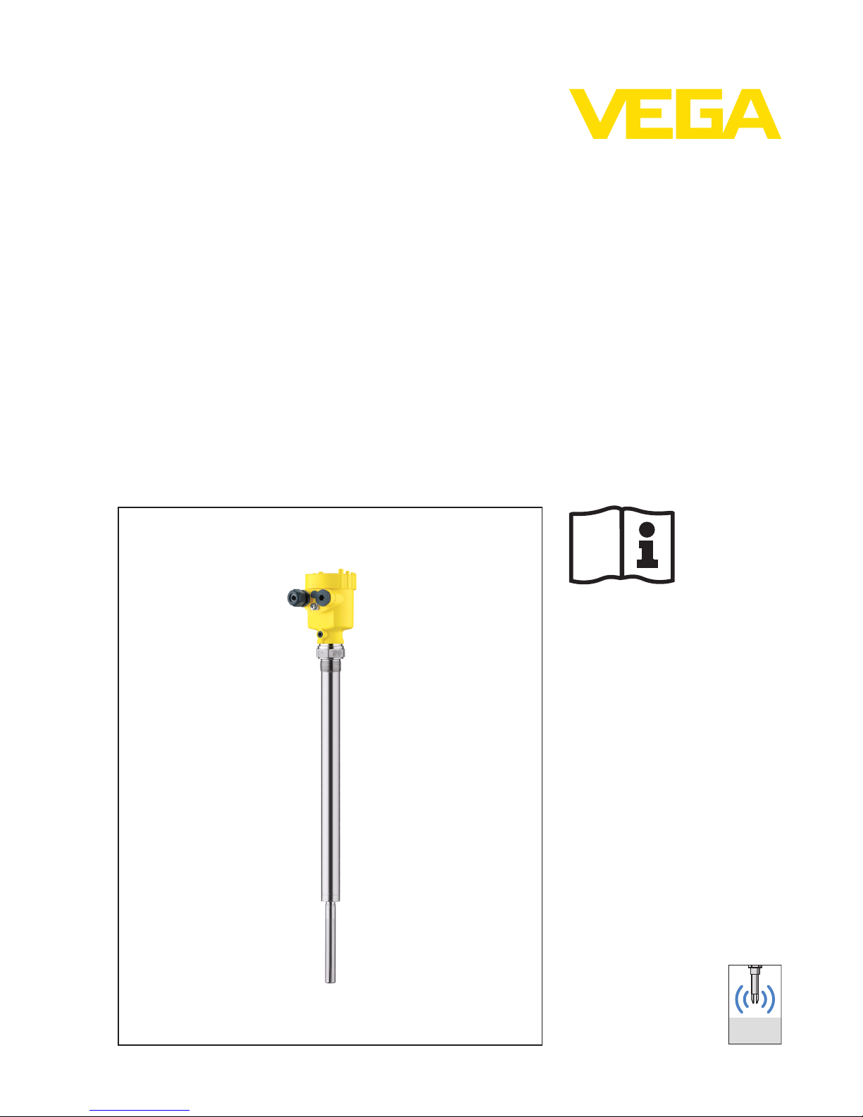
VEGAVIB 63 is a point level sensor with vibrating rod for level
detection.
It is designed for industrial use in all areas of process technology and
is preferably used for bulk solids.
Typical applications are overfill and dry run protection.Thanks to its
simple and robust measuring system,VEGAVIB 63 is virtually
unaffected by the chemical and physical properties of the bulk solid.
It also works when subjected to strong external vibrations or changing
products.
Solid detection in water
IfVEGAVIB 63 was ordered for solid detection in water,the vibrating
rod is calibrated to the density of water.If covered by water (density:
1g/cm³/0.036 lbs/in)VEGAVIB 63 signals "uncovered".Only if the
vibrating element is also covered with solids (e.g.sand,sludge,gravel
etc.) will the sensor signal "covered".
Fault monitoring
The electronics module of VEGAVIB 63 monitors continuously the
following criteria:
lCorrect vibrating frequency
lLine break to the piezo drive
If one of the stated malfunctions is detected or in case of power failure,
the electronics takes on a defined switching condition,i.e.the
contactless electronic switch opens (safe condition).
The vibrating rod is piezoelectrically energised and vibrates at its
mechanical resonance frequency of approx.360 Hz.When the
vibrating rod is submerged in the product,the vibration amplitude
changes.This change is detected by the integrated electronics module
and converted into a switching command.
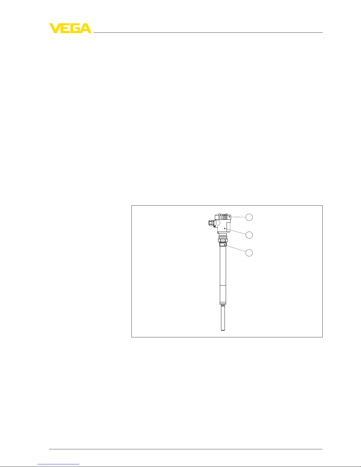
VEGAVIB 63 is a compact instrument,i.e.it can be operated without
external evaluation system.The integrated electronics evaluates the
level signal and outputs a switching signal.With this switching signal,a
connected device can be operated directly (e.g.a warning system,a
pump etc.).
The data for power supply are specified in chapter "Technical data".
Application area
Functional principle
Voltage supply
8VEGAVIB 63 • - contactless electronic switch
3Product description
29278-EN-120418

3.3Operation
With the factory setting,products with a density of >0.05 g/cm³
(0.002 lbs/in³)can be measured.It is possible to adapt the instrument
for products with lower density >0.02 g/cm³(0.0007 lbs/in³).
On the electronics module you will find the following indicating and
adjustment elements:
lSignal lamp for indication of the switching condition (green/red)
lPotentiometer for adaptation to the product density
lMode switch for selecting the switching condition (min./max.)
3.4Storage and transport
Your instrument was protected by packaging during transport.Its
capacity to handle normal loads during transport is assured by a test
according to DIN EN 24180.
The packaging of standard instruments consists of environment-
friendly,recyclable cardboard.In addition,the sensor is provided with
a protective cover of cardboard.For special versions PE foam or PE
foil is also used.Dispose of the packaging material via specialised
recycling companies.
Transport must be carried out under consideration of the notes on the
transport packaging.Nonobservance of these instructions can cause
damage to the device.
The delivery must be checked for completeness and possible transit
damage immediately at receipt.Ascertained transit damage or
concealed defects must be appropriately dealt with.
Up to the time of installation,the packages must be left closed and
stored according to the orientation and storage markings on the
outside.
Unless otherwise indicated,the packages must be stored only under
the following conditions:
lNot in the open
lDry and dust free
lNot exposed to corrosive media
lProtected against solar radiation
lAvoiding mechanical shock and vibration
lStorage and transport temperature see chapter "Supplement -
Technical data -Ambient conditions"
lRelative humidity 20 …85 %
Packaging
Transport
Transport inspection
Storage
Storage and transport
temperature
VEGAVIB 63 • - contactless electronic switch 9
3Product description
29278-EN-120418

4Mounting
4.1General instructions
Make sure that all parts of the instrument exposed to the process,in
particular the sensor element,process seal and process fitting,are
suitable for the existing process conditions.These include above all
the process pressure,process temperature as well as the chemical
properties of the medium.
You can find the specifications in chapter "Technical data"and on the
type label.
In general,VEGAVIB 63 can be installed in any position.The
instrument only has to be mounted in such a way that the vibrating
element is at the height of the desired switching point.
Use the recommended cables (see chapter "Connecting to power
supply")and tighten the cable gland.
You can give your instrument additional protection against moisture
penetration by leading the connection cable downward in front of the
cable entry.Rain and condensation water can thus drain off.This
applies mainly to outdoor mounting as well as installation in areas
where high humidity is expected (e.g.through cleaning processes)or
on cooled or heated vessels.
Fig.2:Measures against moisture penetration
Do not hold VEGAVIB 63 on the vibrating element.Especially with
flange and tube versions,the sensor can be damaged by the weight of
the instrument.
Remove the protective cover just before mounting.
The process fitting must be sealed if there is gauge or low pressure in
the vessel.Before use,check if the seal material is resistant against
the measured product and the process temperature.
Suitability for the pro-
cess conditions
Switching point
Moisture
Transport
Pressure/Vacuum
10 VEGAVIB 63 • - contactless electronic switch
4Mounting
29278-EN-120418

The max.permissible pressure is specified in chapter "Technical data"
or on the type label of the sensor.
The vibrating level switch is a measuring instrument and must be
treated accordingly.Bending the vibrating element will destroy the
instrument.
Warning:
The housing must not be used to screw the instrument in!Applying
tightening force can damage internal parts of the housing.
Use the hexagon above the thread for screwing in.
4.2Instructions for installation
Due to the effects of agitators,equipment vibration or similar,the level
switch can be subjected to strong lateral forces.For this reason,do not
use an overly long extension tube for VEGAVIB 63,but check if you
can mount a short level switch on the side of the vessel in horizontal
position.
Extreme vibration caused by the process or the equipment,e.g.
agitators or turbulence in the vessel,e.g.by fluidisation,can cause the
extension tube of VEGAVIB 63 to vibrate in resonance.This leads to
increased stress on the upper weld joint.Should a longer tube version
be necessary,you can provide a suitable support directly above the
vibrating element to secure the extension tube.
This measure applies mainly to applications in Ex areas.Make sure that
the tube is not subject to bending stress due to this measure.
IfVEGAVIB 63 is mounted in the filling stream,unwanted false
measurement signals can be generated.For this reason,mount
VEGAVIB 63 at a position in the vessel where no disturbances,e.g.
from filling openings,agitators,etc., can occur.
This applies particularly to instrument types with long extension tube.
Handling
Agitators and fluidiza-
tion
Inflowing medium
VEGAVIB 63 • - contactless electronic switch 11
4Mounting
29278-EN-120418

Fig.3:Inflowing medium
VEGAVIB 63 can be mounted with a lock fitting for height adjustment.
Take note of the pressure information of the lock fitting.
The vibrating element should protrude into the vessel to avoid buildup.
For that reason,avoid using mounting bosses for flanges and screwed
fittings.This applies particularly to use with adhesive products.
In silos for bulk solids,material cones can form and change the
switching point.Please keep this in mind when installing the sensor in
the vessel.We recommend selecting an installation location where the
vibrating rod detects an average value of the material cone.
The vibrating rod must be mounted in a way that takes the
arrangement of the filling and emptying apertures into account.
To compensate measurement errors caused by the material cone in
cylindrical vessels,the sensor must be mounted at a distance of d/6
from the vessel wall.
Lock fitting
Socket
Material cone
12 VEGAVIB 63 • - contactless electronic switch
4Mounting
29278-EN-120418

d d
d
6
d
6
Fig.4:Filling and emptying centred
d
d
6
1
2
3
Fig.5:Filling in the centre,emptying laterally
1VEGAVIB 63
2Discharge opening
3Filling opening
VEGAVIB 63 • - contactless electronic switch 13
4Mounting
29278-EN-120418

In applications such as grit chambers or settling basins for coarse
sediments,the vibrating element must be protected against damage
with a suitable baffle.
This baffle must be manufactured by you.
> 125 mm
(> 5")
> 120 mm
(> 4.7")
Fig.6:Baffle for protection against mechanical damage
Baffle protection against
falling rocks
14 VEGAVIB 63 • - contactless electronic switch
4Mounting
29278-EN-120418

5Connecting to power supply
5.1Preparing the connection
Always keep in mind the following safety instructions:
lConnect only in the complete absence of line voltage
In hazardous areas you must take note of the respective regulations,
conformity and type approval certificates of the sensors and power
supply units.
Connect the operating voltage according to the connection diagrams.
The electronics module VB60Cis designed in protection class I.To
maintain this protection class,it is absolutely necessary that the earth
conductor is connected to the inner earth conductor terminal.Keep the
general installation regulations in mind.Take note of the correspond-
ing installation regulations for hazardous areas with Ex applications.
The data for power supply are specified in chapter "Technical data".
The instrument is connected with standard three-wire cable without
screen.If electromagnetic interference is expected which is above the
test values of EN 61326 for industrial areas,screened cable should be
used.
Use cable with round cross-section.Acable outer diameter of 5…9mm
(0.2…0.35 in)ensures the seal effect of the cable gland.If you are
using cable with a different diameter or cross-section,exchange the
seal or use a suitable cable gland.
In hazardous areas,only use approved cable connections for VEGAVIB
63.
Take note of the corresponding installation regulations for Ex
applications.
Cover all housing openings conforming to standard according to
EN 60079-1.
5.2Connection procedure
With Ex instruments,the housing cover may only be opened if there is
no explosive atmosphere present.
Proceed as follows:
1Unscrew the housing cover
2Loosen compression nut of the cable entry
3Remove approx.10 cm (4in)of the cable mantle,strip approx.
1cm (0.4in)of insulation from the ends of the individual wires
4Insert the cable into the sensor through the cable entry
Note safety instructions
Take note of the
safety instru-
ctions for Ex
applications
Voltage supply
Connection cable
Connection cab-
le for Ex appli-
cations
VEGAVIB 63 • - contactless electronic switch 15
5Connecting to power supply
29278-EN-120418

5Lift the opening levers of the terminals with a screwdriver (see
following illustration)
Fig.7:Connection steps 5and 6
6Insert the wire ends into the open terminals according to the wiring
plan
7Press down the opening levers of the terminals,you will hear the
terminal spring closing
8Check the hold of the wires in the terminals by lightly pulling on
them
9Tighten the compression nut of the cable entry.The seal ring must
completely encircle the cable
10 If necessary,carry out a fresh adjustment
11 Screw the housing cover back on
The electrical connection is finished.
5.3Wiring plan,single chamber housing
The following illustrations apply to the non-Ex as well as to the EEx-d
version.
16 VEGAVIB 63 • - contactless electronic switch
5Connecting to power supply
29278-EN-120418

1
4
44
2 3
Fig.8:Material versions,single chamber housing
1Plastic (not with EEx d)
2Aluminium
3Stainless steel (not with EEx d)
4Filter element for pressure compensation (not with EEx d)
We recommend connecting VEGAVIB 63 in such a way that the
switching circuit is open when there is a level signal,line break or
failure (safe condition).
The contactless electronic switch is always shown in non-operative
condition.
Warning:
The instrument must not be operated without an intermediately
connected load,because the electronics would be destroyed if
connected directly to the mains.It is not suitable for connection to low
voltage PLC inputs.
Examples for typical applications:
lLoad resistance at 24 V DC:88 …1800 Ω
lRated power,relay 253 V AC:>2.5VA
lRated power,relay 24 V AC:>0.5VA
For direct control of relays,contactors,magnet valves,warning lights,
horns etc.
Domestic current is temporarily lowered below 1mAafter switching off
the load so that contactors,whose holding current is lower than the
constant domestic current of the electronics,are reliably switched off.
When VEGAVIB 63 is used as part of an overfill protection system
according to WHG,also note the regulations of the general type
approval.
Housing overview
Wiring plan
VEGAVIB 63 • - contactless electronic switch 17
5Connecting to power supply
29278-EN-120418

1
Fig.9:Wiring plan
1Shielding
18 VEGAVIB 63 • - contactless electronic switch
5Connecting to power supply
29278-EN-120418

6Set up
6.1General information
The figures in brackets refer to the following illustrations.
On the electronics module you will find the following indicating and
adjustment elements:
lPotentiometer for adaptation to the product density (1)
lDIL switch for mode adjustment -min./max. (2)
lSignal lamp (5)
Note:
As a rule,always set the mode with mode switch (2)before starting the
setup of VEGAVIB 63.The switching output will change if you set the
mode switch (2)afterwards.This could possibly trigger other
connected instruments or devices.
6.2Adjustment elements
3
4
5
1
2
Fig.10:Electronics and connection compartment -contactless electronic switch
1Potentiometer for switching point adaptation
2DIL switch for mode adjustment
3Ground terminal
4Connection terminals
5Control lamp
With the potentiometer you can adapt the switching point to the solid.It
is already preset and must only be modified in special cases.
Function/Configuration
Electronics and connec-
tion compartment
Switching point adapta-
tion (1)
VEGAVIB 63 • - contactless electronic switch 19
6Set up
29278-EN-120418

As a default setting,the potentiometer of VEGAVIB 63 is set to the
complete right position (>0.3g/cm³/0.011 lbs/in³). In very light solids
you have to turn the potentiometer to the complete left position
(0.02 …0.1g/cm³or 0.0007 …0.0036 lbs/in³). By doing this,
VEGAVIB 63 will be more sensitive and light solids can be detected
more reliably.
For instruments detecting solids in water,these settings are not
applicable.The switching point adaptation is preset and must not be
changed.
With the mode adjustment (min./max.) you can change the switching
condition of the output.You can set the required mode according to
the "Function chart"(max. - max.detection or overflow protection,min.
-min.detection or dry run protection).
We recommend connecting according to the quiescent current
principle (contactless electronic switch is open when the switching
point is reached)because the contactless electronic switch takes on
the same (safe)condition if a failure is detected.
Control lamp for indication of the switching status
lgreen =switch closed
lred =switch open
lred (flashing)=failure
6.3Function chart
The following chart provides an overview of the switching conditions
depending on the adjusted mode and level.
Level Switching status Control lamp
Mode max.
Overflow protec-
tion
21
Switch closed Green
Mode max.
Overflow protec-
tion
21
Switch open Red
Mode min.
Dry run protection
21
Switch closed Green
Mode adjustment (2)
Signal lamp (5)
20 VEGAVIB 63 • - contactless electronic switch
6Set up
29278-EN-120418
Other manuals for VEGAVIB 63
4
Table of contents
Other Vega Switch manuals

Vega
Vega VEGAWAVE 61 User manual

Vega
Vega VEGASWING 51 User manual

Vega
Vega VEGASWING 63 User manual

Vega
Vega VEGACAP 65 User manual

Vega
Vega VEGAWAVE 62 User manual

Vega
Vega VEGASWING 51 User manual

Vega
Vega VEGAKON 61 User manual

Vega
Vega VEGAWAVE 63 User manual

Vega
Vega VEGAWAVE 63 User manual

Vega
Vega VEGAWAVE 61 User manual

Vega
Vega VEGAWAVE 63 User manual

Vega
Vega VEGATOR 121 User manual

Vega
Vega VEGAPOINT 23 User manual

Vega
Vega VEGAPOINT 11 User manual

Vega
Vega VEGAVIB VB6x.EZxxxN series Installation instructions

Vega
Vega VEGAVIB 61 User manual

Vega
Vega VEGASWING 61 User manual

Vega
Vega VEGASWING 61 User manual

Vega
Vega VEGAVIB 62 User manual

Vega
Vega VEGASEL 643 User manual