Veit Brisay BRI-7570/101 FPD User manual
VEIT Garment & Textile
Technologies GmbH & Co.
Valdorfer Straße 100
D-32602 Vlotho / Germany
Tel.: ++49 0) 57 33 / 87 13-0
Fax: ++49 0) 57 33 / 87 13-45
e-mail: info@veit-kannegiesser.de
Internet: www.veit-kannegiesser.com
Ein Unternehmen der Veit-Gruppe
GB
USA
Translation of Instruction anual
Variant
Machine no.:
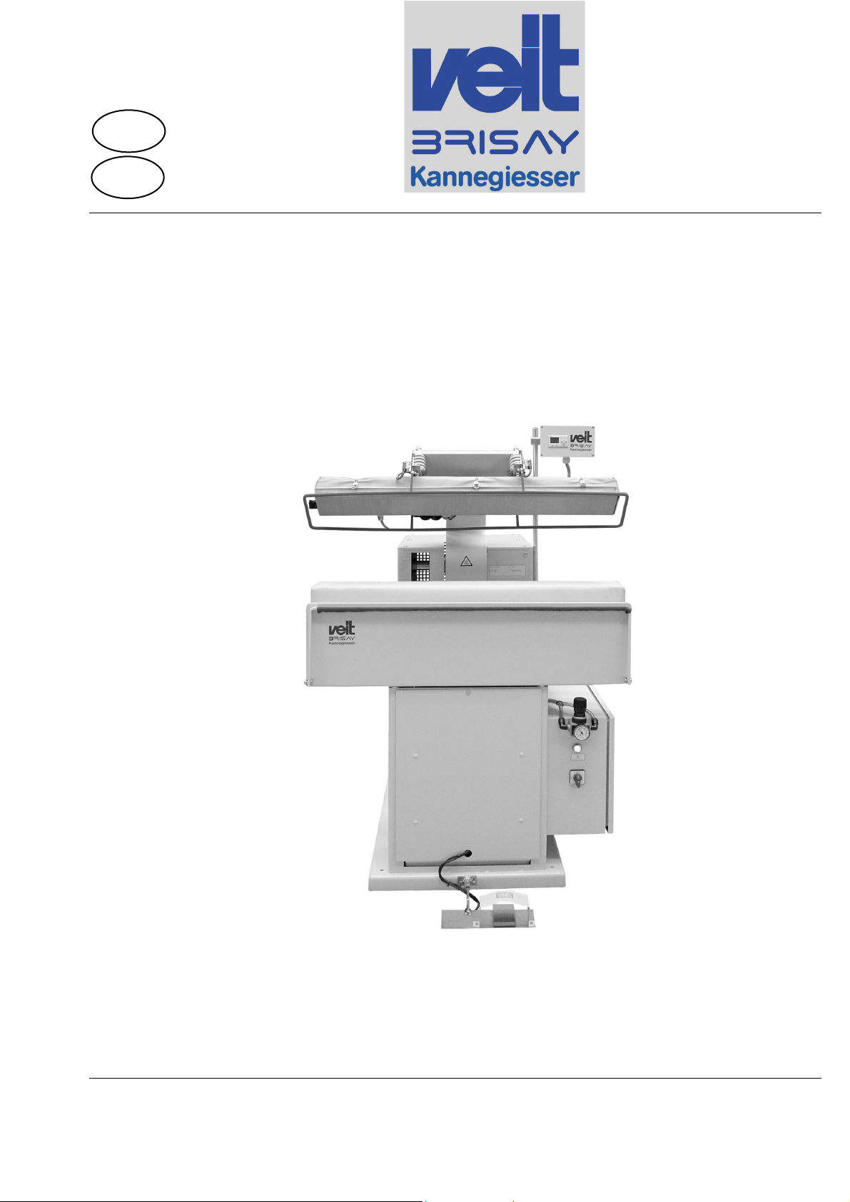
BRI-7570/101 FPD
FRONT PLACKET DEVICE

Translation
In case of the machine being delivered in EEA countries, the operating instructions must be
translated into the language of the country of destination. Should the translation reveal incon-
sistencies, the user is obliged to consult the original operating instructions German) or to con-
tact the manufacturer.
Should the machine be sold and delivered to another EEA country at a later point in time, the
operating instructions have to be translated into the language of the relevant country of destina-
tion.
Copyright
This document as well as the information contained in it are protected by copyright and must
not be copied as a whole or in parts or made available to third parties without the written con-
sent of the editor.
© Copyright Brisay-Maschinen GmbH, 63762 Grossostheim-Ringheim, Germany

Intended use
14.02.11 BRI-7570_020 i
Table of contents
1. Intended use ...................................................................... 1
1.1. Description of the machine ......................................... 2
1.2. Function ...................................................................... 3
1.3. Technical data............................................................. 4
1.4. Scope of delivery ........................................................ 5
2. Safety................................................................................. 7
2.1. Warning symbols and danger signs........................... 7
2.1.1. Designation of the machine.................................... 8
2.2. Safety standards ......................................................... 9
2.3. Built-in safety systems .............................................. 10
2.4. Safety measures ....................................................... 12
2.5. Safety tests ............................................................... 13
3. Potential dangers ............................................................. 15
3.1. Dangerous areas of the machine.............................. 16
3.2. Duties of the operating company .............................. 17
3.3. Operating and maintenance staff.............................. 18
3.4. Disconnect procedures ............................................. 19
4. Transport and packing ..................................................... 21
4.1. Delivery ..................................................................... 21
4.2. Unloading and transport to the place of installation . 22
4.2.1. Lifting points ......................................................... 26
5. Installation........................................................................ 27
5.1. Setting-up.................................................................. 27
5.2. Installation................................................................. 29
5.3. Commissioning ......................................................... 31
5.3.1. Setting instructions suction valve (option) ............ 32
6. Operation ......................................................................... 33
6.1. Operator’s controls and displays............................... 33

Table of contents
ii BRI-7570_020 14.02.11
6.1.1. Switch cabinet.......................................................34
6.1.2. Process control .....................................................35
6.1.3. Pedal strip.............................................................38
6.2. Starting the machine .................................................39
6.3. Pressing in automatic operation ................................39
6.4. Switching off the machine .........................................40
7. Maintenance .....................................................................41
7.1. Changing of pressing covers .....................................41
7.1.1. Changing cover of lower buck...............................43
7.1.2. Changing cover of heating plate ...........................44
8. Maintenance / Cleaning...................................................45
8.1. Cleaning ....................................................................47
8.2. Maintenance and inspection table .............................48
8.2.1. Machine checks ....................................................49
9. Defects, Cause, Elimination .............................................51
9.1. Trouble shooting via process control.........................54
10. Emergency....................................................................55
11. Dismantling / Disposal..................................................57
12. Spare parts lists ............................................................59
12.1. Cover material........................................................61
13. EC declaration of conformity.........................................63
Intended use
14.02.11 BRI-7570_020 1
1. INTENDED USE
This machine has been developed, designed and built for
industrial and commercial use only.
The front placket device BRI-7570 FDP glues front plackets of
shirts and blouses by applying heat and pressure.
Note The machine is intended for the working of textiles only.
The
manufacturer shall not assume any responsibility for
modifications and changes which are not stated in the
declaration of conformity.
If the place of installation does not comply with the intended
use, reb
uilding measures must be taken to obtain a higher
level of protection (see chapter 1.3, Technical data).
This machine serves the above-mentioned purpose only.
Any
other or further use as well as any rebuilding or retrofitting of
the machine without the
written consent of the manufacturer
will be considered as non-compliance with the intended use.
The manufacturer shall not be liable for damages caused by
such use. The user alone bears the risk.
This also applies to the installation and setting-up of sa
fety
equipment and valves as well as to any changes in the
supporting parts of the machine.
The intended use also comprises the observance of operating
instructions and compliance with the inspection and
maintenance intervals prescribed by BRISAY.
Table of contents
Other Veit Brisay Industrial Equipment manuals


