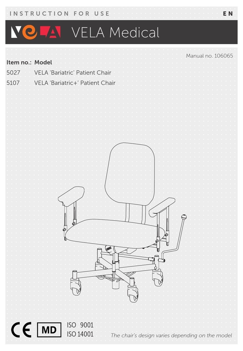
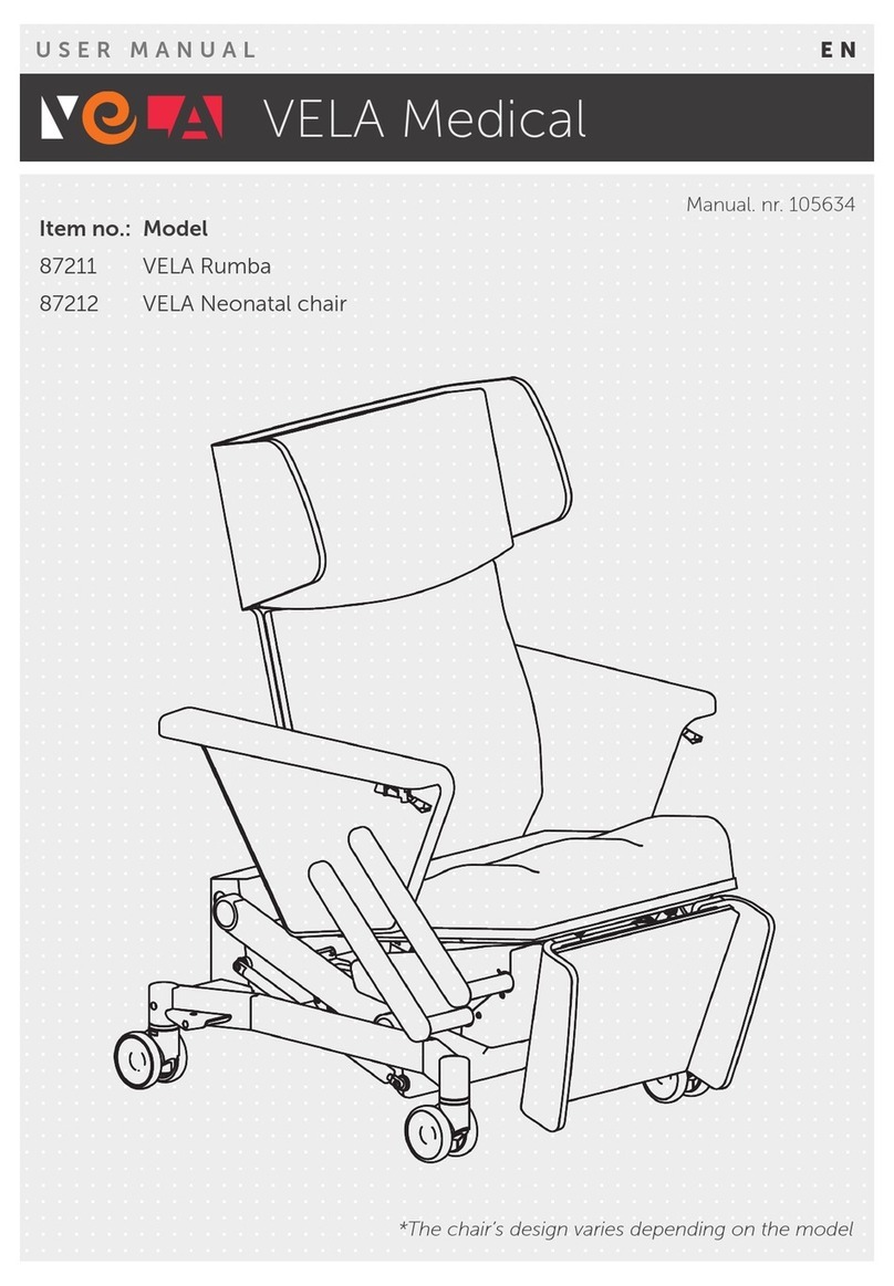
Vela Treatment Chair User manual

ISO 9001
ISO 14001
VELA Medical
INSTRUCTION FOR USE EN
Manual. nr. 105634
Item no.: Model
87211 VELA Rumba
87212 VELA Neonatal chair
87213 VELA Treatment Chair
*The chair’s design varies depending on the model

2
TABLE OF CONTENTS
1.0. INTRODUCTION 3
1.1. WARNINGS 4
1.2. ELECTROMAGNETIC EMISSION 5
1.3. LABELS USED ON THE CHAIR 6
1.4. SAFETY 6
1.4.1. Intended use 6
1.4.2. Transport 6
1.5. WARRANTY 7
1.6. UNWRAPPING THE CHAIR 7
1.7. MAINTENANCE 7
1.7.1. Wheels 7
1.7.2. Frame & wooden surfaces 7
1.7.3. Upholstery 8
1.8. RECYCLING AND DISPOSAL 8
1.9. PLACING/REMOVING PILLOWS 9
1.9.1. Footrest 9
1.9.2. Seat 9
1.9.3. Backrest 9
2.0. QUICKGUIDE – REMOTE CONTROL 10
2.0.1. Lift (seat height) 10
2.0.2. Seat angle and footrest 10
2.0.3. Backrest angle 10
2.0.4. Neutral and trendelenburg positions* 10
2.1. SETTINGS 11
2.1.1. Using the brakes 11
2.1.2. Using the footrest 11
2.1.3. Adjusting the armrest 11
2.1.4. Adjusting the neck pillow 11
2.1.5. Using the front brakes* 12
2.1.6. Battery* 12
2.2. ELECTRICAL FEATURES 13
2.2.1. Lift (up or down) 13
2.2.2. Alighting assistance and footrest 13
2.2.3. Backrest angle 14
2.2.4. Neutral position 14
2.2.5. Trendelenburg* 15
2.2.6. Neutral position and trendelenburg* 15
2.3. TECHNICAL DATA AND DOCUMENTATION 16
2.3.1. Specifications 16
2.3.2. Storage and transportation 16

3
DEAR CUSTOMER
Congratulations on your new VELA Medical chair.
This user guide contains helpful information about
adjustments, operation, and maintenance.
Important
To help you get the most benefit from your chair,
please read this user guide carefully and keep it handy
for future reference. You can also find this user guide
on VELA Medical’s website: www.vela-medical.com
along with other relevant information about the chair.
If you have questions, experience errors or adverse
events, please contact your VELA Medical dealer.
We reserve the right to make changes.
VELA Medical
Gøteborgvej 8-12
9200 Aalborg SV
Denmark
www.vela-medical.com
1.0. INTRODUCTION

4
1.1. WARNINGS
Use The chair is intended for indoor use in hospital settings.
Use The chair is not suitable for use outside hospital settings.
Use The chair does not have electrical accessories.
Use The chair is only intended for use by adults.
Use The chair must not be used for operations or in contagious wards, as the chair cannot be
run through a washer.
Use We recommend annual servicing where the chair is checked for defective or worn
elements.
Use Batteries must be disposed of at recycling plants in the respective containers for batte-
ries/electrical garbage (refer to section 1.8. Recycling and Disposal).
Use The chair must be cleaned and maintained in accordance with Section 1.7. Maintenance.
Use The footrest is not designed to be sat upon.
Use The armrest is not designed to be sat upon.
Use The backrest is not designed to be sat upon when lowered to a position where this is
possible.
Use When adjusted to the Trendelenburg position, the chair has been designed to take the
patient’s weight only.
Use The maximum load for the chair is 140 kg.
Use Take care not to get hands or limbs trapped in moving parts when using the electrical
features (marked with yellow warning labels).
Use The chair should not be sat upon during transportation.
Use To prevent unintended adjustments, all electrical features are inactivated when the
remote control button is released.
Use Make sure that cables and service cables do not pose a tripping hazard.
Use Make sure the chair is not driven over cables or service cables.
Electric noise The chair must be kept at least 30 cm from other electrical equipment, including electri-
cal wires/cables.
Use If the chair runs on battery, make sure the battery is charged 24 hours before use!

5
1.2. ELECTROMAGNETIC EMISSION
RF emission CISPR 11, Group 1, Class A
Harmonic Emissions IEC 61000-3-2, Class A
Voltage changes/fluctuations and flickers IEC 61000-3-3
NOTE: The EMISSIONS specifications for this equipment make it suitable for use in industrial areas and hospitals (CISPR 11 Class A).
If the chair is used in a residential environment (which normally requires CISPR 11 Class B), this equipment might not provide
adequate protection for radiofrequency communication services. The user might have to take necessary precautions,
such as moving or adjusting the equipment.
Immunity Test Test Level Professional Healthcare
Electrostatic discharge (ESD) IEC 61000-4-2 ± 8 kV contact disharge
± 2,4,6,8,15 kV air discharge
Radiated RF field IEC 61000-4-3 3 V/m
80 MHz – 2.7 GHz
80% AM 1 kHz
Proximity fields from wireless transmitters
IEC 61000-4-3
80 MHz to 2700Hz. 3V/m
Spot Test: 385 MHz. at 27V/m;
(710,745,780,5240,5500,5785) MHz. at 9V/m;
(450,810,870,930,1720,1845,1970,2450) MHz. At 28V/m
Electrical fast transient / burst IEC 61000-
4-4
± 2kV, AC mains
± 1kV, I/0 ports
100 kHz PRR
Surge IEC 61000-4-5
AC mains, Line to Ground
AC mains, Line to Line
± 0.5, 1, 2 kV
± 0.5, 1 kV
Conducted RF IEC 61000-4-6 3 V (0.15 – 80 MHz)
6 V ISM Bands
80% AM 1 kHz
Power frequency (50/60 Hz) magnetic field
IEC 61000-4-8
30 A/m – 50 or 60 Hz
Voltage dips, short interruptions and voltage
variations on power supply input lines IEC
61000-4-11
100% dip, 0.5 periods, 0°, 45°, 90°, 135°, 180°, 225°, 270°, 315°
100% dip, 1 period 30% dip,
25/30 periods (50/60 Hz) Interrupt 100% drop, 5 sec.

6
1.4. SAFETY
This chair has CE certification and approval
for the model name “VELA Rumba” and
adheres to EU regulations.
The chair is manufactured by:
VELA Medical, Gøteborgvej 8-12,
9200 Aalborg SV, Denmark.
The VELA Rumba complies with all electri-
cal safety requirements according to IEC
60601-1, including requirements for EMC
according to IEC60601-1-2.
1.4.1. INTENDED USE
This device is intended to support a user in
a sitting/resting posture in hospital environ-
ments.
The chair may be used in wards where
non-invasive treatment is administered.
The chair must not be used outside
a hospital setting.
:: The chair is not designed to be stood
upon.
:: To ensure the safe transfer of an individ-
ual on and o the chair, the brakes must
be activated.
All versions of the chair have been tested
and approved for a maximum user weight
of 140 kg.
1.4.2. TRANSPORT
When transporting the chair by car, plane,
or other means of transport, it must be
securely packed!
GENERAL
1.3. LABELS USED ON THE CHAIR
Warning Risk of shear and squeeze:
Keep hands and fingers away from moving parts
Do not sit on the footrest
Icon
Read ”Instruction For Use” before use
Labels 60 x 22.5 mm
The last six digits are the product ID number:
Labels on the chair should be read at a distance of approx. 40 cm under normal
daylight conditions.
For labels related to the operation of the chair, please refer to section 2.0.
UDI:
<Model name>
<Model ref. no.>
<Manufacturer>
<Adress>
<Webpage>
<Safe working load>
<Production date/order no.>
(XX) XXXXXXXXXXXXXX (XX) XXXXXX
MEDICO
SID IKKE PÅ
LÆGSTØTTEN
60
60

7
:: Adjust the height upwards approx. 10 cm,
so that there are no moving parts below
frame height. This is checked by moving
the foot/hand along the lower edge of
the frame side.
:: The hand control is turned to “locked”
with the supplied blue key.
:: All brakes on castors must be activated.
The chair is not approved as a passenger
seat in means of transport and must
therefore not be used as such.
The chair is fit for the following transport
specifications:
Temperature: - 10°C to + 45°C (refer to
Section 1.4.2 Upholstering)
Humidity: 15% to 95%
Allow the chair to stand for 24 hours before
use if it has been stored below 0°C.
1.5. WARRANTY
VELA Medical oers warranties in accord-
ance with the laws of the country in which
the chair is sold. The warranty is only appli-
cable for chairs using authentic spare parts
and accessories, and for chairs that have
been modified by authorised technicians.
Note: This is subject to change if special
contractual obligations have been estab-
lished with VELA Medical.
VELA Medical is not liable for damages to
the product or the user arising from:
:: Transport
:: Misuse
:: Standard wear and tear
:: Incorrect use
:: Use of spare parts and accessories
not manufactured by VELA
:: Modifications carried out
by unauthorised technicians
1.6. UNWRAPPING THE CHAIR
If the chair is delivered with missing parts
or transport-related damages, contact VELA
Medical immediately. In such an event, do
not attempt to repair any damages yourself
or start using the chair.
Contents of Delivery:
:: Chair and any accessories
:: User guide for the chair.
1.7. MAINTENANCE
We recommend annual servicing of the
chair to identify any defective or worn parts.
All removable parts must be tightened
regularly.
With annual servicing, the lifespan of the
chair is 5 years of daily use up to 8 hours a
day.
1.7.1. WHEELS
We recommend checking and cleaning
the wheels regularly to remove flu,
hair, and dirt.
1.7.2. FRAME & WOODEN SURFACES
Frame and all wooden surfaces are
surface treated with resistant varnish.
Clean with lukewarm water, and pH-
neutral soap if needed.

8
1.7.3. UPHOLSTERY
Magic Premium by Cotting Group:
Abrasion resistance: About 500,000
Martindale, ISO 5470-2
Biocompatibility: ISO 10993-10:2014
Lightfastness: Light ≥ 6; perspiration
(ISO 11641): Class 4
Surface resistance: Blood/urine (EN
12720)
Flame protection: BS 5852 crib 5, B2
(DIN 4102), EN 1021.1-2, IMO A652,
temperature: -40°C to + 70°C
Maintenance: Regularly wipe down
the PU textile with clean, warm water
and pH-neutral soap. Use a clean,
white, soft cloth or sponge. Wipe
down with a clean, wrung-out cloth.
Vacuum with a soft brush.
Stains: Remove immediately using
an absorbent cloth.
Disinfection: The textile must be
cleaned prior to disinfection.
The following cleaning products
can be used: 70% Ethanol (hospital
disinfectant) ISO 1164, or chlorine-
based products with 5,000 ppm
active chlorine, such as Actichlor
Plus. We advise following the
instructions on the packaging.
After cleaning/disinfection, the chair
must be wiped down several times
with a clean, wrung-out cloth.
1.8. RECYCLING AND DISPOSAL
This product contains recyclable
materials. For this reason, the product
must be disposed of in accordance
with local legislation and not with
regular household items.
Correct disposal and recycling
reduce the negative impact on the
environment and human beings.
Note: Electrical and electronic
equipment as well as batteries
contain materials, components,
and elements that can be harmful to
human health and the environment
if not handled correctly.
Electrical and electronic equipment,
as well as batteries, are marked
with a symbol to show they must be
disposed of independently and not
with unsorted household waste.
It is important to take your used
batteries to the established venues
to ensure they are reused in
accordance with legislation and do
not cause unnecessary harm to the
environment.

1a 1a 1b
1b
3a
3b
2
1a
1a
1a
1a 3a
3b
2
6
6
57
78
1
4
2
3b
3a
1b
9
1.9.3. BACKREST
1. Bring the wire (1) up through the hole (2) at the base of the backrest until fixed in place. Note: rubber ring
(3a) must be pushed totally in place in the mounting (3b)!
2. The wire (4) is attached to the anchor (5) on the wooden frame.
3. The two holes (7) on the backrest is hinged on the metal bracket (6) Note: be carefull not to pull the wire
that connects the backrest and the wooden frame.
4. Push the backrest (8) down so the backrest slips into place.
Note: once the backrest has been mounted, test the back angle. If the backrest shifts against the wooden
frame, the length compensation is working as intended and the backrest pillow has been mounted correctly.
When removing pillows, follow the instructions in reverse!
1.9.2. SEAT
1. Place seat pillow (1a) against the metal frame (1b).
2. Ensure that the metal frame catches the hold on the seat plate so that the seat (2) does not move.
3. Click the cover (3a) onto the seat pillow (3b) to mount correctly.
Note: there are buttons on both sides of the cover facing the backrest and footrest.
1.9.1. FOOTREST
1. Push the pillow against the footrest so the holes (1a) are pressed into the rubber brackets (1b).
2. Push the pillow firmly in place so that it cannot be moved up or down.
3. Click the cover (3a) onto the seat pillow (3b) to mount correctly.
Note: there are buttons on both sides of the cover.
1.9. PLACING/REMOVING PILLOWS

1a. 1b.
2b.
3b.
4b.
2a.
3a.
4a.
10
Remote Control
Can be placed on the hanger or behind the chair.
Note: if the remote control is to be moved to the other side of the chair, this must
always be done by bringing it behind the chair in order to avoid pinching hazards.
2.0.2. SEAT ANGLE AND FOOTREST
Press the button on the left (2a) for assistance to get out of the
chair. Press the button on the right (2b) for resting position.
Note: footrest responds to the seat angle.
Warning! Beware of trapping hands or limbs
underneath the chair when using alighting assistance.
2.0.3. BACKREST ANGLE
Press the button on the left (3a) to angle the backrest forwards.
Press the button on the right (3b) to angle the backrest backwards.
Warning! Do not sit on the backrest.
2.0.1. LIFT (SEAT HEIGHT)
Press the button on the left (1a) to lower the chair or press the
button on the right (1b) to raise the chair.
Warning! Beware of trapping hands or limbs
underneath the chair when using the lift.
Warning!
Beware of people around the chair and trapping hands or
limbs in moving parts when using the electrical features.
2.0. QUICKGUIDE – REMOTE CONTROL
2.0.4. NEUTRAL AND TRENDELENBURG POSITIONS*
Press the (green) button on the left (4a) to reset the chair to a
neutral position.
Press the (red) button on the right (4b) (additional purchase) to
adjust the chair into Trendelenburg (time: 20 seconds).
*Note: Not all chairs are equipped with the Trendelenburg feature!
Before Use: The supplied blue ”key” must be used at the back of the hand control to turn from
locked to open ”padlock”. This in order to use the chair’s electrical functions.

11
2.1.3. ADJUSTING THE ARMREST
Pull up the handle under the armrest and push the armrest
down. The armrest will lock again when the handle is released.
The armrest can be raised by activating
the handle again.
Warning! Do not sit on the armrest.
2.1.4. ADJUSTING THE NECK PILLOW
The neck pillow can be adjusted using counterweight.
Push the neck pillow up or down to the desired height.
2.1.2. USING THE FOOTREST
The footrest follows the seat angle.
Refer to Section 2.0.2 Seat Angle and Footrest.
Warning! Do not sit on the footrest.
2.1.1. USING THE BRAKES
Press down on the brake pedal on the right or left side of the
chair to apply the brake to the back wheels. Red to engage the
brake. Green to disengage the brake.
Refer to Section 2.1.5 Using the Front Brakes.
Note: the pedal applies the brakes to the two back wheels.
Modifications and repairs to the chair must only be carried out by a
VELA Medical technician or a person with the required training.
2.1. SETTINGS

12
2.1.6. BATTERY*
The battery allows the user to use all electrical functions without needing a
socket – even Trendelenburg (additional purchase). The battery is charged
when the chair is plugged into a socket (charging time: 8 hours). ). An LED
light on the battery is illuminated in red during charging and turns green
once the battery is fully charged. The LED light can only be seen when
alighting assistance is activated. The chair should be charged every day.
Not all chairs are equipped with a battery.
2.1.5. USING THE FRONT BRAKES*
Double wheels with button-activated brakes. Press the buttons on the
right and left side of the chair to engage brakes completely.
Note: the button-activated brakes only engage two front wheels and
should always be used with the pedal (Section 2.1.1.).
*Depending on the model

13
2.2.2. ALIGHTING ASSISTANCE AND FOOTREST
The button on the left activates alighting assistance. The button on the
right sets the chair to a seated position and activates the footrest to a
resting position (break for 0.5 seconds in neutral position) (Figure 2).
Note: footrest follows the seat angle.
Warning! Beware of trapping hands or limbs
underneath the chair when using alighting assistance.
2.2.1. LIFT (UP OR DOWN)
The button on the left lowers the seat.
The button on the right raises the seat (Figure 1).
Warning! Beware of trapping hands or limbs
underneath the chair when using the lift.
2.2. ELECTRICAL FEATURES
Lift upNeutral/Lift down
Neutral Footrest engagedAlighting assistance
Figure 1
Figure 2

14
2.2.4. NEUTRAL POSITION
The green button resets the seat height, back angle,
and footrest to the neutral position (Figure 4).
The process sequence for resetting to the neutral position is 1.
Backrest up, 2. Seat angle neutral, and 3. Seat down.
Note: if the chair is equipped with the Trendelenburg feature,
this feature also resets to the neutral position (Section 2.2.6.).
2.2.3. BACKREST ANGLE
The button on the left angles the backrest forwards. The but-
ton on the right angles the backrest backwards (Figure 3).
Note: the backrest can only be serviced when the seat is in a
horizontal position (Sections 2.0.2./2.0.4.).
Maximum back anglingNeutral
Neutral
Figure 3
Figure 4

15
2.2.6. NEUTRAL POSITION AND TRENDELENBURG*
The (green) button on the left resets the chair to the neutral
position (Figure 6).
The process sequence for resetting to the neutral position is 1.
Trendelenburg tilt to neutral, 2. Backrest up, and 3. Seat down.
Note: not all chairs are equipped with the Trendelenburg feature!
2.2.5. TRENDELENBURG*
The (red) button on the right angles the seating unit to Trende-
lenburg (backrest horizontal, footrest up) (Figure 5).
Note: not all chairs are equipped with the Trendelenburg feature!
Trendelenburg
Neutral
Maximum back angling/footrest engaged
Trendelenburg
*Depending on the model
Figure 5
Figure 6

701.5518 © Vermund Larsen A/S
VELA Medical :: Gøteborgvej 8-12 :: 9200 Aalborg SV :: Denmark :: Tel: +45 96 34 76 00 :: [email protected] vela-medical.com
2.3.1. SPECIFICATIONS
Maximum external measures
(armrest and footrest horizontal): 180 cm x 81 cm
Weight: 91 kg
Wheel size: 100 mm
Minimum/maximum seat height: 47-87 cm
Back angling: 43° (110°-153°)
Trendelenburg back angling (additional purchase): Horizontal position, 0°
Maximum load: 140 kg
Electrical potential: 230V (for regular sockets)
Battery (additional purchase): Li-Ion 25.2V, 1800 mAH, IP66
2.3. TECHNICAL DATA AND DOCUMENTATION
2.3.2. STORAGE AND TRANSPORTATION
The chair is intended for indoor use and storage.
The electrical cable (on the back of the chair) must be rolled
up during transportation.
Note: the chair must not be sat upon during transportation.
This manual suits for next models
5
Table of contents
Other Vela Medical Equipment manuals