Velbus VMB4RYNO User manual

V
V
VM
M
MB
B
B4
4
4R
R
RY
Y
YN
N
NO
O
O
Programmable
4-channel relay module
for Velbus system

2VMB4RYNO 4-channel relay module user manual - version 1
INDEX
INDEX........................................................................................................................................2
DESCRIPTION...........................................................................................................................3
CHARACTERISTICS.................................................................................................................3
VELBUS CHARACTERISTICS .................................................................................................5
OVERVIEW................................................................................................................................6
LED INDICATIONS....................................................................................................................7
LOCAL CONTROL....................................................................................................................8
USE............................................................................................................................................9
Mains Voltage Connection Diagram .......................................................................................9
Low-Voltage Connection Diagram........................................................................................11
Termination...........................................................................................................................12
Configuration........................................................................................................................13
Address.............................................................................................................................13
Relay Contact Behaviour ..................................................................................................13
Control Functions..............................................................................................................13
CHECKING THE SOFTWARE VERSION ...............................................................................17

VMB4RYNO 4-channel relay module user manual - version 1 3
DESCRIPTION
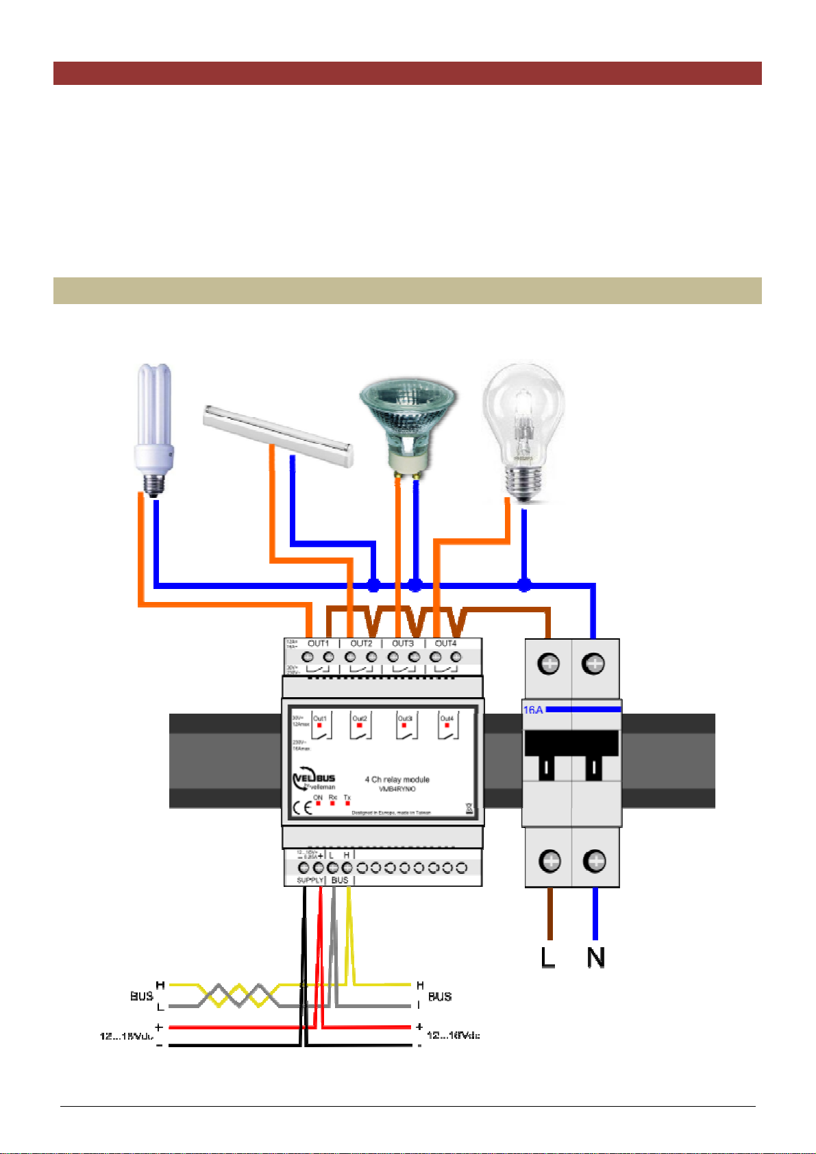
This relay module is suited for switching on or off the lighting in the living room, the garden fountain, the mains
outlets in the children’s room, and many more. This is only suited for use in a Velbus system.
Multiple functions, e.g. switching on/off timers, are to be programmed via the Velbuslink software.
CHARACTERISTICS
Use:
•suitable for switching on/off mains-powered or low-voltage lighting or consumers
•only suitable for use in a Velbus installation
Outputs:
•4 single-pole NO relay contacts
•relay contact debounce
•switching capacity:
o16A @ 230VAC input voltage
o12A @ 30VDC input voltage
oallowed switch-on current up to 80A (lamp switch-on current)
•each relay channel may be inverted in order to simulate an NC contact
•1 extra virtual channel
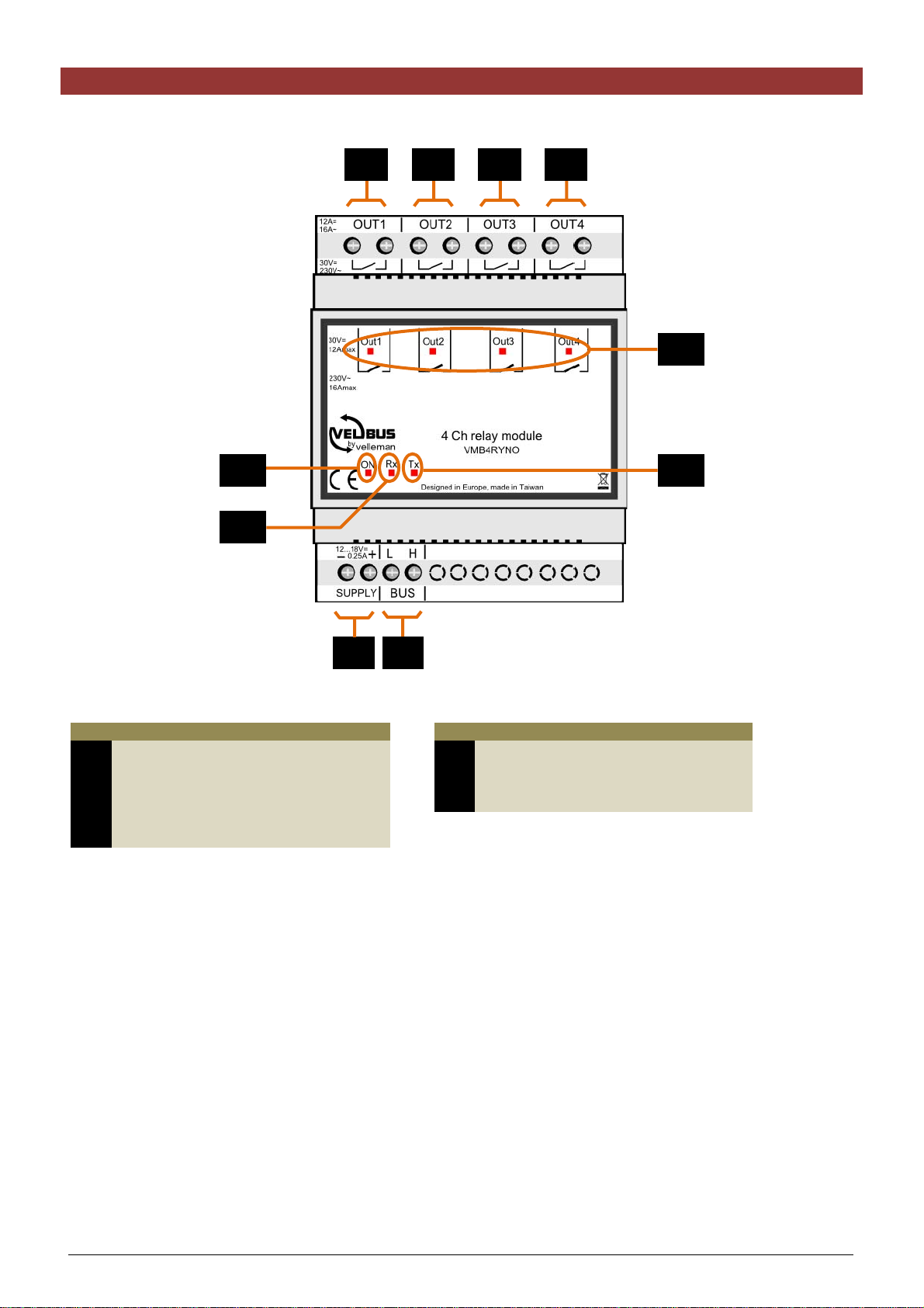
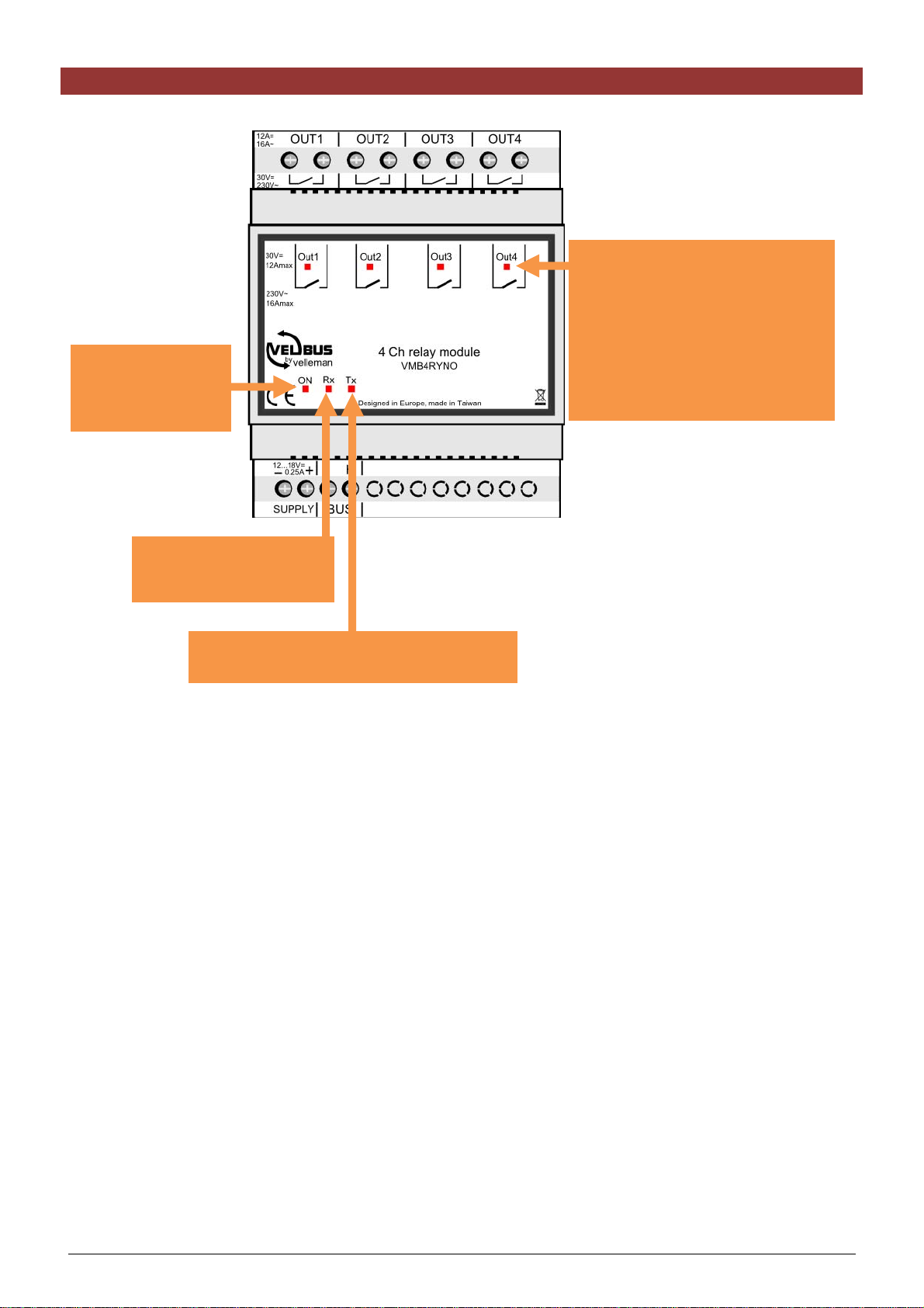
LED indications:
•status indication for all 4 channels
ocontinuously lit: relay switched on
oslow blinking: timer 1 running
ofast blinking: timer 2 running
otwo short blinks: communication error
•power voltage present
•data reception and transfer over the Velbus
•status notification of the relay channels to the control modules
Module power supply:
•required power voltage: 12...18VDC
•consumption in stand-by: 30mA
•max. consumption: 250mA
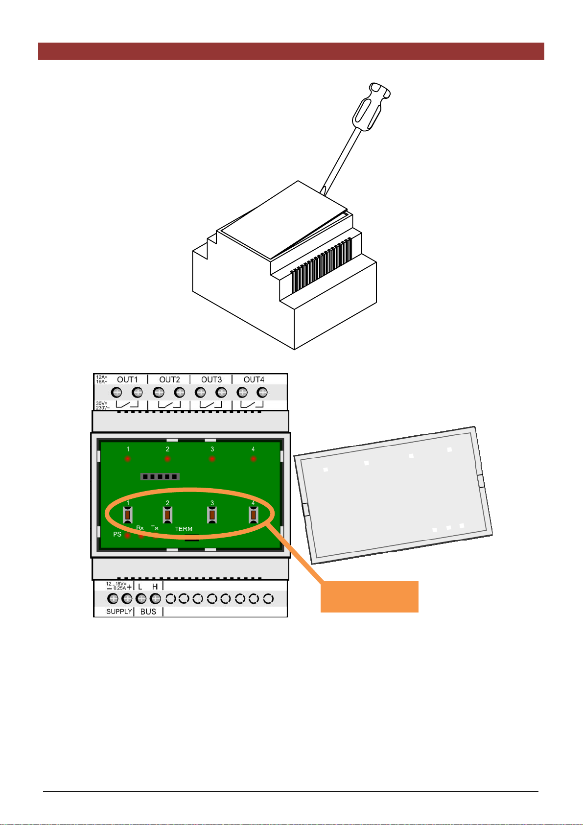
Dimensions:
•standard DIN-rail housing: 4 modules
•L x W x H: 90 x 71 x 58mm
Configuration:
•only configurable via the Velbus PC interface (VMB1USB, VMB1RS or VMBRSUSB) and the Velbuslink
software
•addressing through software (up to 250 addresses)
•storage space for 39 different pushbuttons and their function
•multiple functions and timer settings are configurable through software
•learned pushbuttons are saved in case of a power failure
Control:
•local on/off control on the module
•no direct pushbutton connections
•through Velbus commands or pushbuttons connected to the Velbus system
•multiple control functions
omoment
ooff
oon
oon/off
otimer (start/stop, restartable or non-restartable, switch-on/off delay, interval)
ooutput forced off
ooutput forced on
ooutput inhibition
oetc.

4VMB4RYNO 4-channel relay module user manual - version 1
Timer presets:
•only configurable through the Velbuslink software
•timer presets configurable between:
o1 sec and 2 min in steps of 1 sec
o2 min and 5 min in steps of 15 sec
o5 min and 30 min in steps of 30 sec
o30 min and 1 hour in steps of 1 min
o1 hour and 5 hours in steps of 15 min
o5 hours and 10 hours in steps of 30 min
o10 hours and 24 hours in steps of 1 hour
o2 days
o3 days
ono switch-off timer

VMB4RYNO 4-channel relay module user manual - version 1 5
VELBUS CHARACTERISTICS
•2-wire communication for Velbus data and 2 wires for power
•data transfer: 16.6 kbit/s
•serial data protocol: CAN (Controller Area Network)
•short-circuit proof (towards (-) or (+) of power)
•bus error indication: 2 short blinks of the operation mode LED
•self-restoring after 25 seconds in case of a bus error
Possibility to assign a name (max. 16 characters) to each output channel.
The relay module can send following messages:
•relay status
•relay module type (with software version)
•channel names
•communication error counter
•memory capacity
The relay module can send following commands:
•switch off LEDs on a control module
•switch on LEDs on a control module
•slow or fast blinking of the LEDs on a control module
The relay module can receive following messages:
•pushbutton module status
The relay module can receive following commands:
•switch on relay channel
•switch off relay channel
•start timer
•start blinking timer
•recall relay status
•recall module type and software version
•recall communication error counter
•recall relay names
•recall memory contents
•overwrite memory contents
•switch off pushbutton indication LED

6VMB4RYNO 4-channel relay module user manual - version 1
OVERVIEW
Connections LED indications
1 Relay contact channel 1 7 power LED
2 Relay contact channel 2 8 Velbus RX (receive) LED
3 Relay contact channel 3 9 Velbus TX (transmit) LED
4 Relay contact channel 4 10 output status
5 Velbus
6 Velbus power supply
1
6 5
9
8
7
10
2 3 4

VMB4RYNO 4-channel relay module user manual - version 1 7
LED INDICATIONS
Output LED:
•off when consumer is switched off
•on when consumer is switched on
•blinks rapidly when timer 1 is
running
•blinks slowly when timer 2 is
running
•blinks shortly twice at
communication error
On LED:
lights when power
voltage is present
Rx LED:
lights at Velbus data
reception
Tx LED:
lights at Velbus data transfer

8VMB4RYNO 4-channel relay module user manual - version 1
LOCAL CONTROL
Remove the cover.
Local control:
on or off

VMB4RYNO 4-channel relay module user manual - version 1 9
USE
The relay module features 4 non-voltage NO contacts wich allow you to switch mains-voltage (230V) and low-
voltage (12 or 24V) consumers.
The module is integrated into the Velbus system and controlled through the VMB4PD control panel or by means
of pushbuttons connected to a VMB8PB pushbutton interface, VMB6IN or any other relay module.
To interconnect the Velbus modules it is recommended to use a twisted-pair cable (EIB 2x2x0.8mm², UTP
4x2x0.51mm² - CAT5 or equivalent).
Make sure to use a heavy-gauge wire (0.5mm2or more) in case of a multiple module connection (>10 modules) or
with log connections (>50m).
Connect the bus to the module (mind the polarity).
Mains Voltage Connection Diagram
A single-pole load (e.g. lighting) can be connected directly to the output.

10 VMB4RYNO 4-channel relay module user manual - version 1
A double-pole load (e.g. mains outlet) requires an extra double-pole relay.
A triple-pole load (e.g. water heater) requires a quadrupole relay.

VMB4RYNO 4-channel relay module user manual - version 1 11
Low-Voltage Connection Diagram
The module is also suitable for controlling 12V or 24V LED bulbs or strips. The input will then be connected to a
low-voltage power supply (12V or 24V). Choose a power supply which can deliver the required consumption while
the total consumption does not exceed 12A.

12 VMB4RYNO 4-channel relay module user manual - version 1
Termination
Remove the cover.
Generally, only 2 ‘TERM’ terminators must be used in a complete Velbus®installation. Usually, this will be on one
module inside the distribution box and on the module which is physically located furthest from the distribution box.
On all other modules, the terminator must be removed.
Remark:
In case of a wiring with multiple branches, only place a termination into a single module in the distribution box and
in the control panel which is the farthest from the distribution box. When communication problems occur, you can
place an extra termination on another branch. It is highly recommended to limit the number of terminations as too
large a number may overload the bus.
Termination

VMB4RYNO 4-channel relay module user manual - version 1 13
Configuration
This relay module can only be configured through the Velbuslink software.
The address, behaviour and control functions can be configured manually.
Address
Each module in the Velbus connection must have a unique address.
Configure the address through the software.
Relay Contact Behaviour
The relay contact will behave as an NO contact (no voltage on the outputs at no load).
With the software, this behaviour can be modified to an NO contact: at no load (when the indication LED does not
light) the relay contact will be closed and the output will present a voltage. Make sure however this occurs when
the relay module is live.
Control Functions
The relay module is controlled through pushbuttons connected to the Velbus system via a pushbutton interface or
control panel.
You may assign up to 39 different pushbuttons. Each pushbutton may activate a different function.
Function Description
1 Momentary The relay remains switched on as long as the pushbutton is
pressed.
2 Off The relay is switched off.
In order to create an “all off” function, the same pushbutton of all
relay channels will be configured as an off function.
3 Off with timers disabled The relay is switched off and the timers cannot be restarted.
4 Off with timers disabled at
short press A short press of the pushbutton switches off the relay but the
timers cannot be restarted.
A long press of the pushbutton switches off the relay and the
timers remain enabled.
5 Off with timers disabled at long
press A short press of the pushbutton switches off the relay and the
timers remain enabled.
A long press of the pushbutton switches off the relay but the
timers cannot be restarted.
6 On The relay is switched on.
May be used in a control panel with weekly program to switch on
an output at a certain point in time.
7 On with timers disabled The relay is switched on and the timers cannot be restarted.
When a PIR detector is triggered, the driveway lighting will switch
on for 10 minutes.
A pushbutton with the “On with timers disabled” function allows to
switch on the driveway lighting continuously without the PIR
detector having an influence on the action.
8 On with timers disabled at
short press A short press of the pushbutton switches on the relay but the
timers cannot be restarted.
A long press of the pushbutton switches on the relay and the
timers remain enabled.
9 On with timers disabled at long
press A short press of the pushbutton switches on the relay and the
timers remain enabled.
A long press of the pushbutton switches on the relay but the
timers cannot be restarted.
10 Toggle Each press toggles the relay status (on/off).
Normal lighting control in a room.

14 VMB4RYNO 4-channel relay module user manual - version 1
11 Toggle with timers disabled Each press toggles the relay status (on/off).
The timers cannot be started when the relay is switched on.
A PIR detector will switch on the driveway lighting; this lighting
can switched on/off with a pushbutton. A driveway lighting
switched on through the pushbutton will not be affected by the PIR
detector.
12 Toggle with timers disabled at
short press Each press toggles the relay status (on/off).
The timers cannot be started when the relay was switched on by a
short press.
13 Toggle with timers disabled at
long press Each press toggles the relay status (on/off).
The timers cannot be started when the relay was switched on by a
long press.
14 Start/stop timer A press of the pushbutton switches on the relay for a preset time.
A press of the pushbutton switches off the switched-on relay
immediately.
If desired, the short and long press delays can be set.
Control of the lighting in the attic. The lighting will automatically
switch off after a preset time.
15 Restartable timer A press of the pushbutton switches on the relay for a preset time.
A press of the pushbutton while the relay is switched on restarts
the timer.
If desired, the short and long press delays can be set.
This function is also called a staircase lighting timer.
16 Non retriggerable timer A press of the pushbutton switches on the relay for a preset time.
A press of the pushbutton while the relay is switched on has no
effect.
17 Trigger-on-release timer The relay status remains unchanged with the closing of the
switch.
The relay is switched on for a preset time with the opening of the
switch.
18 Delayed off at release The relay is switched off with the closing of the switch.
The relay remains switched on for a preset time with the opening
of the switch.
19 Delayed off at release only
when relay is on Nothing happens as long as the relay remains switched off. At the
release of the pushbutton, the switched-on relay will remain
switched on for a preset time.
20 Start/stop with delayed on/off Pressing the pushbutton will switch on the relay after the
expiration of the switch-on delay. The relay is switched off again
after expiration of the switch-off delay.
Pressing the pushbutton while the switch-on or switch-off delay is
running will annul the timer and switch off the relay.
21 Restartable delayed on/off Pressing the pushbutton will switch on the relay after the
expiration of the switch-on delay. The relay is switched off again
after expiration of the switch-off delay.
Pressing the pushbutton while the switch-on delay is running will
restart the switch-on delay.
22 Non restartable delayed on/off Pressing the pushbutton will switch on the relay after the
expiration of the switch-on delay. The relay is switched off again
after expiration of the switch-off delay.
Pressing the pushbutton while the switch-on or switch-off delay is
running does not affect the general status.
23 Start/stop interval timer Pressing the pushbutton will switch on the interval timer for a
preset time. The output is thus repeatedly open and closed. The
switch-on and switch-off delays can be set.
Pressing the pushbutton while the interval timer is running will
stop the interval timer.

VMB4RYNO 4-channel relay module user manual - version 1 15
24 Restartable interval timer Pressing the pushbutton will switch on the interval timer for a
preset time. The output is thus repeatedly open and closed. The
switch-on and switch-off delays can be set.
Pressing the pushbutton while the interval timer is running will
restart the interval timer.
25 Non restartable interval timer Pressing the pushbutton will switch on the interval timer for a
preset time. The output is thus repeatedly open and closed. The
switch-on and switch-off delays can be set.
26 Forced off at closed switch The relay cannot be switched on as long as the switch is closed.
A light sensor will keep the driveway lighting switched off during
daylight.
27 Forced off at opened switch The relay cannot be switched on as long as the switch is open.
28 Forced off at pushbutton press Pressing the pushbutton will disable the switching-on of the relay
for a preset time.
The use of a control panel with weekly program allows you to
disable the output control of an output for a preset time.
29 Toggle forced off at
pushbutton press Pressing the pushbutton will disable the switching-on of the relay
for a preset time.
Repressing that same pushbutton will cancel the forced-off mode.
30 Cancel forced off at
pushbutton press Pressing the pushbutton will cancel the forced-off mode.
Remark:
The forced-off status can still be determined by the function forced
off at opened or closed switch.
31 Forced on at closed switch The relay is switched on as long as the switch is closed. All other
commands are ignored.
Remark:
The forced-off function overrules the forced-on function.
32 Forced on at open switch The relay is switched on as long as the switch is open. All other
commands are ignored.
Remark:
The forced-off function overrules the forced-on function.
33 Forced on at pushbutton press Pressing the pushbutton will switch on the relay. All other
commands are ignored for a preset time.
Remark:
The forced-off function overrules the forced-on function.
34 Toggle forced-on at
pushbutton press Pressing the pushbutton will switch on the relay. All other
commands are ignored for a preset time. Repressing that same
pushbutton will cancel the forced-on mode.
Remark:
The forced-off function overrules the forced-on function.
35 Cancel forced-on at
pushbutton press Pressing the pushbutton will cancel the forced-on mode.
Remark:
The forced-on status can still be determined by the function forced
off at opened or closed switch.
36 Inhibit at closed switch The relay is switched off as long as the switch is closed. The
functions will still be active internally. The internal status will be
transferred to the relay at the opening of the switch.
37 Inhibit at open switch The relay is switched off as long as the switch is open. The
functions will still be active internally. The internal status will be
transferred to the relay at the closing of the switch.
38 Inhibit at pushbutton press Pressing the pushbutton will switch off the relay for a preset time.
The functions will still be active internally.
39 Toggle inhibit at pushbutton
press Pressing the pushbutton will switch off the relay for a preset time.
The functions will still be active internally. Repressing that same
pushbutton will cancel the inhibition mode.

16 VMB4RYNO 4-channel relay module user manual - version 1
40 Cancel inhibit at pushbutton
press Pressing the pushbutton will transfer the internal status to the
relay.
A light sensor will switch on the garden lighting at dusk. A
pushbutton on the control panel will inhibit the output at 23h00; a
second pushbutton will cancel this inhibition at 06h00 via the
weekly program. This will keep the garden lighting switched off
between 23h00 and 06h00.
Some functions allow you to set the switch-off time, the switch-on delay or the pulse and pause time between:
o1 sec and 2 min in steps of 1 sec
o2 min and 5 min in steps of 15 sec
o5 min and 30 min in steps of 30 sec
o30 min and 1 hour in steps of 1 min
o1 hour and 5 hours in steps of 15 min
o5 hours and 10 hours in steps of 30 min
o10 hours and 24 hours in steps of 1 hour
o2 days
o3 days
ono switch-off timer

VMB4RYNO 4-channel relay module user manual - version 1 17
CHECKING THE SOFTWARE VERSION
The software version can be verified via the Velbus link software.
Check on http://www.velbus.eu whether you have the latest version. If a newer version is available, download it.
Connect the Velbus interface to a PC and run the upgrade-software and follow the instructions on the screen.
Remark:
Upgrading a module is not without risk. Do not interrupt the process!
If for any reason the upgrade should fail, the module will cease normal operation. The module will have to be
returned to the manufacturer.

18 VMB4RYNO 4-channel relay module user manual - version 1
Refer to our website for more information: www.velbus.be
Table of contents
Other Velbus Relay manuals