Wieland SNT 4M63K User manual
1
Gebrauchsanweisung (Original-Betriebsanleitung)
BA000538 - 09/2013 (Rev. D)
SNT 4M63K / K-A
SUPPLY
K1
K2
A1
SNT4M63K
S23 13
S24 23
S33 33
S34
S13
A2 S14
14 S35
24 S22
34
Basisgerät für Not-Aus- und Schutztür-Anwendungen
Basisgerät nach EN 60204-1:2005 und EN ISO 13849-1:2008
PL e nach EN ISO 13849-1:2008
Kategorie 4 nach EN ISO 13849-1:2008
Stop-Kategorie 0 gemäß DIN EN 60204-1
Manueller oder automatischer Start
Querschlusserkennung
Rückführkreis zur Überwachung externer Schütze
3 Freigabestrompfade
Anti- und äquivalente Ansteuerung
Überwachung von Magnetschaltern gemäß DIN EN 60947-5-3
Geräteausführungen
SNT 4M63K mit Schraubklemmen
SNT 4M63K-A mit Steckblockklemmen
Frontansicht
SUPPLY
K1
K2
LED grün Versorgungsspannung
LED grün Relais K1
LED grün Relais K2
Sicherheitsbestimmungen
Geräte- und Funktionsbeschreibung
Das Gerät ist ein zweikanaliges, bei jedem EIN-AUS-Zyklus sich selbst überwachendes Sicher-
heitsschaltgerät nach DIN EN 60204-1, welches mit zwangsgeführten Relais ausgestattet ist. Es
dient der elektrischen Überwachung angeschlossener Schaltelemente an trennenden Schutzein-
richtungen und der Erzeugung eines sicherheitsgerichteten Ausgangssignales (Freigabe). Die
trennenden Schutzeinrichtungen können, je nach Bauart Schutzgitter, Schutztür, Gehäuse, Abde-
ckung, Verkleidung, Schirm usw. sein.
Grundfunktion: Nach Anlegen der Versorgungsspannung an die Klemmen A1/A2 und geschlosse-
nen Sicherheitseingängen werden mit der Betätigung des Reset-Tasters (manueller Start) die Frei-
gabestrompfade geschlossen. Beim Öffnen der Sicherheitseingänge werden die Freigabepfade
geöffnet.
Betriebsarten / Systemfunktionen
Zweikanalige Ansteuerung Das Gerät wird zweikanalig angesteuert. Bei äquivalenter An-
steuerung wird der Sicherheitskanal CH1 über Pluspotential, der Sicherheitskanal CH2 über
Minuspotential geschaltet. Bei antivalenter Ansteuerung werden die beiden Sicherheitskanä-
le gegen Pluspotential geschaltet.
Querschlusserkennung Die Querschlusserkennung wird bei äquivalenter Ansteuerung über
das Kurzschlussprinzip, bei antivalenter Ansteuerung durch Funktionsdiversität erreicht.
Manueller Start Mittels eines Tasters wird, bei geschlossenen Sicherheitseingängen, der
Reseteingang S34 geschlossen und anschließend geöffnet (Triggerung mit fallender Flanke)
oder der Reseteingang S35 geschlossen (Triggerung mit steigender Flanke).
Automatischer Start Der Reseteingang S35 wird mit S33/S14 verbunden. Das Gerät startet
mit der steigenden Flanke des Signals am Sicherheitseingang S14.
Anlaufsperre Beim Anlegen der Versorgungsspannung und geschlossenen Sicherheitsein-
gängen werden die Freigabepfade nicht geschlossen. Der Anlauf kann nur nach der Betäti-
gung des Reset-Tasters erreicht werden. Für die Anlaufsperre sind, wie bei der Betriebsart
Manueller Start, die Reseteingänge mit Taster anzusteuern.
Wiederanlaufsperre Nach Öffnen und Schließen der Sicherheitseingänge erfolgt kein erneu-
ter Anlauf. Der Wiederanlauf kann nur nach der Betätigung des Reset-Tasters erreicht wer-
den. Für die Wiederanlaufsperre sind, wie bei der Betriebsart Manueller Start, die Resetein-
gänge mit Taster anzusteuern.
Synchronüberwachung
Die Synchronüberwachung ist nur beim automatischen Start möglich
(Brücke S33/S14 - S35). Nach Sicherheitskanal CH1 muss innerhalb der Synchronzeit tSder
Sicherheitskanal CH2 schließen (S24) bzw. öffnen (S22). Schließt/öffnet CH2 vor CH1, beträgt
die Synchronzeit tS= .
Bitte beachten Sie auch die Informationen Ihrer Berufsgenossenschaft!
Die Montage, Inbetriebnahme,
Ä
nderung und
Nachrüstung darf nur von einer Elektrofachkraft
ausgeführt werden!
Schalten Sie das Gerät/ die Anlage vor Beginn
der Arbeiten spannungsfrei! Bei Installations-
und Anlagenfehlern kann bei nicht galvanisch
getrennten Geräten auf dem Steuerkreis Netz-
potential anliegen!
Beachten Sie für die Installation der Geräte die
Sicherheitsvorschriften der Elektrotechnik und
der Berufsgenossenschaft.
Durch Öffnen des Gehäuses oder sonstige Ma-
nipulation erlischt jegliche Gewährleistung.
Achtung!
Bei unsachgemäßen Gebrauch oder nicht be-
stimmungsgemäßer Verwendung darf das Gerät
nicht mehr verwendet werden und es erlischt
jeglicher Gewährleistungsanspruch. Nicht zu-
lässige Einwirkungen können sein:
starke mechanische Belastung des Gerätes, wie
sie z.B. beim Herunterfallen auftritt, Spannun-
gen, Ströme, Temperaturen, Feuchtigkeit au-
ßerhalb der Spezifikation.
Bitte überprüfen Sie gemäß der geltenden Vor-
schriften bei Erstinbetriebnahme Ihrer Maschi-
ne/ Anlage immer alle Sicherheitsfunktionen
und beachten Sie die vorgegebenen Prüfzyklen
für Sicherheitseinrichtungen.
Achtung!
Führen Sie vor Beginn der Installation/ Montage
oder Demontage folgende Sicherheitsmaßnah-
men durch:
1. Schalten Sie das Gerät/ die Anlage vor Be-
ginn der Arbeiten spannungsfrei!
2. Sichern Sie die Maschine/ Anlage gegen
Wiedereinschalten!
3. Stellen Sie die Spannungsfreiheit fest!
4. Erden Sie die Phasen und schließen Sie
diese kurz!
5. Decken und schranken Sie benachbarte,
unter Spannung stehende Teile ab!
6. Der Einbau der Geräte muss in einem
Schaltschrank mit einer Schutzart von
mindestens IP 54 erfol
g
en.
Achtung!
Eingeschränkter Berührungsschutz! Schutzart
nach DIN EN 60529.
Gehäuse/Klemmen: IP 40 / IP 20.
Fingersicher nach DIN VDE 0660 Teil 514.

2
Bestimmungsgemäße Verwendung
Die Geräte sind Sicherheits-Schaltgeräte. Sie dürfen nur als Teil von Schutzeinrichtungen an Maschinen zum Zweck des Personen-, Material- und Maschi-
nenschutzes eingesetzt werden.
Hinweise
Der Performance Level (PL) sowie die Sicherheits-Kategorie nach EN ISO 13849-1 hängt von der Außenbeschaltung, dem Einsatzfall, der Wahl der Be-
fehlsgeber und deren örtlicher Anordnung an der Maschine ab.
Der Anwender muss eine Risikobeurteilung nach ISO 14121-1 durchführen.
Auf dieser Basis muss eine Validierung der Gesamtanlage / -maschine nach den einschlägigen Normen durchgeführt werden.
Der angegebene Performance Level (PL) wird nur erreicht, wenn je nach vorliegender Belastung des Gerätes (vergl. EN ISO 13849-1, Tab. C.1) und dem
Anwendungsfall eine mittlere Anzahl von Schaltzyklen pro Jahr nicht überschritten wird (vergl. EN ISO 13849-1, C.2.4 und Tab. K.1). Mit einem ange-
nommenen
B
10d-Wert für maximale Last von 400.000 ergibt sich z.B. eine maximale Zyklenanzahl von 400.000 / 0,1 x 30 = 133.333 Schaltzyklen / Jahr.
Das Betreiben des Gerätes außerhalb der Spezifikation kann zu Funktionsstörungen oder zur Zerstörung des Gerätes führen.
Der Versorgungseingang A1 dient auch als Steuereingang, dadurch können kurze Unterbrechungen oder eine Absenkung unterhalb von UB
zum Schalten der Freigabepfade führen.
Grundsätzlich sind beim Betrieb des Gerätes die angegebenen Zeiten einzuhalten, ansonsten kann es zur Verriegelung des Gerätes kommen.
Die Verriegelung kann durch ordnungsgemäßes Öffnen der Sicherheitseingänge aufgehoben werden.
Zur Vervielfältigung der Freigabestrompfade können die Erweiterungsgeräte der Reihe SNE oder externe Schütze mit zwangsgeführten Kon-
takten eingesetzt werden.
Das Gerät und die Kontakte müssen mit maximal 6 A Betriebsklasse gG abgesichert werden.
Die Geräte sind mit einem Überlastschutz (bei Kurzschluss) ausgerüstet. Nach Beseitigung der Störungsursache ist das Gerät nach ca. 3 s
wieder betriebsbereit.
Der Steuerausgang S13 dient ausschließlich dem Anschluss von Befehlsgebern laut Gebrauchsanweisung und nicht dem Anschluss externer
Verbraucher, wie z.B. Lampen, Relais oder Schützen.
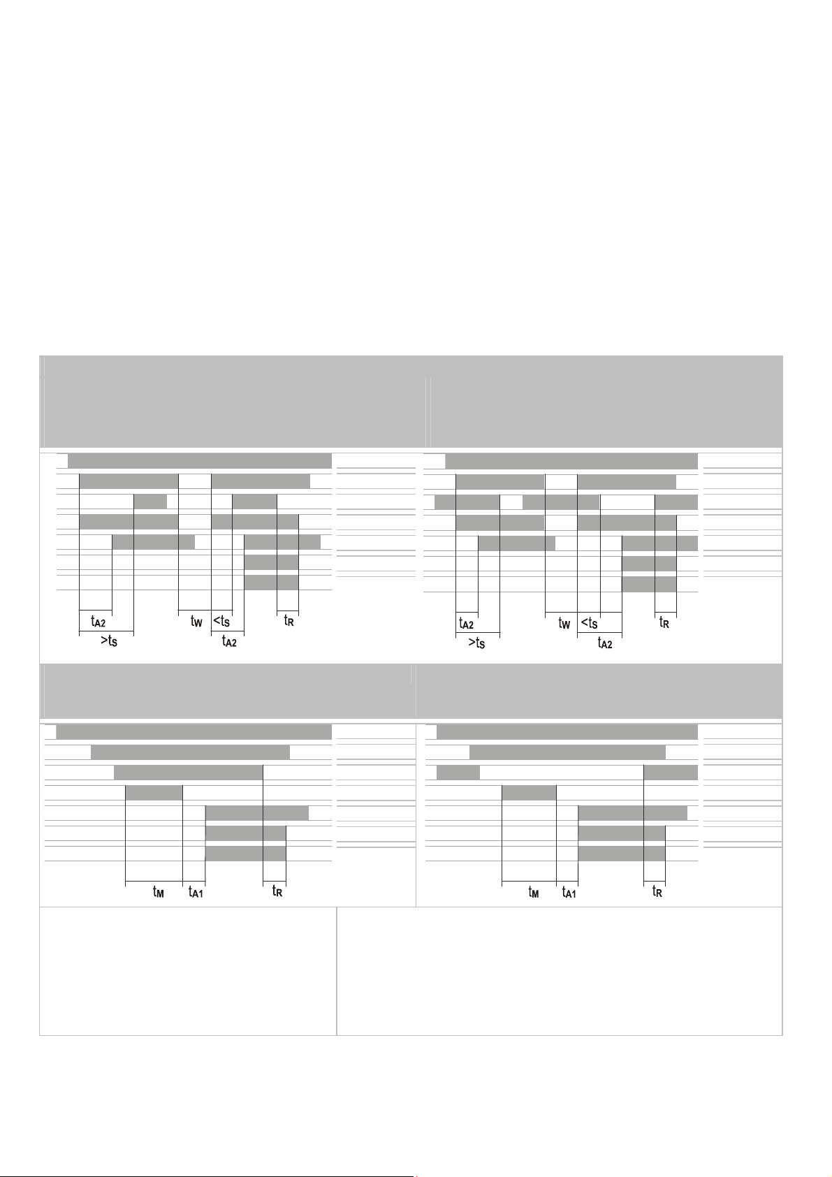
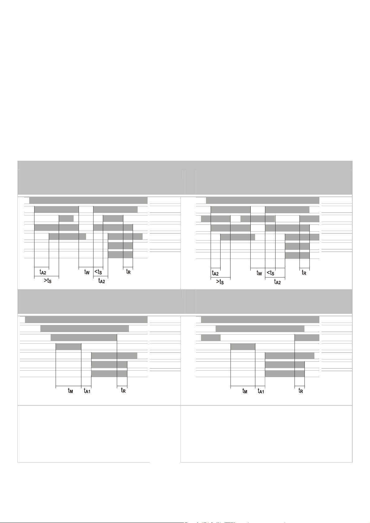
Funktionsdiagramme
SNT 4M63K
automatischer Start, Synchronüberwachung,
äquivalente Ansteuerung (Installation 4)
SNT 4M63K
automatischer Start, Synchronüberwachung,
antivalente Ansteuerung (Installation 1)
A1/A2 A1/A2
S14
S14
S24
S22
S35
S35
K1
K1
K2
K2
13/14,
23/24,
33/34
13/14,
23/24,
33/34
SNT 4M63K
manueller Start, äquivalente Ansteuerung
(Installation 5)
SNT 4M63K
manueller Start, antivalente Ansteuerung
(Installation 2)
A1/A2 A1/A2
S14
S14
S24
S22
S34
S34
K1
K1
K2
K2
13/14,
23/24,
33/34
13/14,
23/24,
33/34
tM= Mindesteinschaltzeit
tA1 / tA2 = Ansprechzeit
tS= Synchronüberwachungszeit
tW= Wiederbereitschaftszeit
tR= Rückfallzeit

3
Technische Daten
Versorgungskreis
Nennspannung UNAC/DC 24 V, AC 115 - 120 V, AC 230 V
Bemessun
g
sleistun
g
DC 2,0 W
Bemessun
g
sleistun
g
AC 2,6 W / 3,2 VA
Restwelligkeit U
SS
2,4 V
Nennfrequenz 50 ... 60 Hz
Betriebsspannungsbereich 0,85 ... 1,1 x UN
Sicherung für Steuerkreisversorgung kurzschlussfest
(DC-Geräte: PTC-Widerstand / AC-Geräte: kurzschlussfester Trafo)
Steuerkreis
A
usgänge S13, S23
Nennausgangsspannung S13, S23 DC 22 V
Leerlaufspannun
g
AC-Gerät < 40 V
Aus
g
an
g
sstrom 100 mA
Kurzschlussfest / Strombegrenzung
j
a / nein
Eingänge S14/S33, S22, S24, S34, S35
Eingangsspannungsbereich (nur bei DC-Geräten für externe Ein-
speisung) DC 17,4 V bis DC 26,4 V
Nennstrom / Spitzenstrom S14/S33, S22, S24 40 mA / 100 mA
Nennstrom / Spitzenstrom S34, S35 5 mA / 50 mA
Zeiten
zulässi
g
e Testpulszeit tTP / Testhäufi
g
keit
1000
s /
10 s-
1
Ansprechzeit tA1 S34 20 ms bis 40 ms
Ansprechzeit tA2 S35 200 ms bis 600 ms
Ansprechzeit tA3 100 ms bis 400 ms
Mindesteinschaltdauer tMS34, S35 > 80 ms
Synchronzeit t
S
(CH1 vor CH2) ca. 200 ms
Wiederbereitschaftszeit tW100 ms
Rückfallzeit tR K1, K2 < 25 ms
Ausgangskreis
Freigabepfade
Kontaktbestückung 3 Schließer, zwangsgeführt
Schaltnennspannung UnAC 230 V
max. Dauerstrom Inpro Strompfad 6 A
Absicherun
g
Max. 6 A Betriebsklasse
g
G / Schmelzinte
g
ral < 100 A²s
max. Summenstrom aller Strompfade 9A²
Gebrauchskategorie nach DIN EN 60947-5-1 AC-15: Ue 230 V, Ie 3 A
DC-13: Ue 24 V, Ie 2,5 A
Mechanische Lebensdauer (Schaltun
g
en)
107
Allgemeine Daten
Luft- und Kriechstrecken zwischen den Stromkreisen DIN EN 60664-1
Ü
berspannun
g
skate
g
orie IV
Bemessungsstoßspannung 4 kV
Verschmutzungsgrad des Gerätes: innerhalb / außerhalb 2 / 3
Bemessungsspannung 300 V
Prüfwechselspannung 2 kV
Schutzart nach DIN EN 60529 Gehäuse / Klemmen IP 40 / IP 20
Um
g
ebun
g
s-/La
g
ertemperatur -25 ... +55 °C / -25 ... +75 °C
Klimatische Anwendungsklasse H V G nach DIN 40040: 04:87
Gewicht DC-Gerät
0,21 kg
AC-Gerät
0,25 kg
Klemmen- und Anschlussdaten Schraubklemmen Federkraftklemmen
Eindrähtig oder feindrähtig 1 × 0,2
–
2,5 mm² / 2 × 0,2
–
1,0 mm² 2 × 0,2
–
1,5 mm²
Feindrähti
g
mit Aderendhülse nach DIN 46228 1 × 0,25
–
2,5 mm² / 2 × 0,25
–
1,0 mm² 1 × 0,25–1,5 mm² (Trapezverpressung)
AWG 26
–
14 24
–
16
Maximales Anzugsdrehmoment 0,5
–
0,6 Nm (4
–
5lbf-in) —
Abisolierlänge max. 7 mm
4
Translation of the original instructions
BA000538 - 09/2013 (Rev. D)
SNT 4M63K / -A
SUPPLY
K1
K2
A1
SNT4M63K
S23 13
S24 23
S33 33
S34
S13
A2 S14
14 S35
24 S22
34
Base Device for Emergency Stop and Safety Gate Applications
Basic device to EN 60204-1:2005 and EN ISO 13849-1:2008
PL e / category 4 in accordance with EN ISO 13849-1:2008
SILCL 3 in accordance with EN 62061:2005
Stop category 0 to DIN EN 60204-1
Manual or automatic start
Cross monitoring
Feedback circuit for monitoring external contactors
3 enabling current paths
Equivalent and non-equivalent activation
Monitoring of magnetic switches to DIN EN 60947-5-3
Device style
SNT 4M63K with screw terminals
SNT 4M63K-A with plug-in terminals
Front View
SUPPLY
K1
K2
LED green Power Supply
LED green Relay K1
LED green Relay K2
Safety Instructions
Description of Device and Function
This device is a two-channel safety switching device with self-monitoring on each ON-OFF cycle. It
conforms to DIN EN 60204-1 and is equipped with positively driven relays. It is intended for
monitoring connected switching elements on separating safety devices and generating a safety-
oriented output signal (enable). Depending on the design, separating safety devices may include
protective screens, safety doors, enclosures, covers, screens, etc.
Basic function: After supply voltage has been connected to terminals A1/A2 and the safety inputs
closed, operating the reset button closes the enabling current paths (manual start). When the
safety inputs are opened the enabling current paths will open.
Operating modes / system functions
Two-channel activation The device uses two-channel activation. With equivalent activation
safety channel CH1 is connected via positive potential, safety channel CH2 via negative
potential. With non-equivalent activation both safety channels are connected to positive
potential.
Cross monitoring With equivalent activation cross monitoring is achieved by means of the
short-circuit principle; with non-equivalent activation it is achieved through functional
diversity.
Manual start When the safety inputs are closed, a button is used to close reset input S34
and then open it again (triggering with falling edge) or to close reset input S35 (triggering
with rising edge).
Automatic start Reset input S35 is connected to S33/S14. The device starts with the rising
edge of the signal on safety input S14.
Starting lockout After supply voltage has been connected and the safety inputs closed, the
enabling paths will not close. Starting is only possible after the reset button has been
operated. For starting lockout the reset inputs have to be activated with the button, as in
manual start mode.
Restarting lockout No restart after the safety inputs have been opened and closed.
Restarting is only possible after the reset button has been operated. For restarting lockout the
reset inputs have to be activated with the button, as in manual start mode.
Synchro-check
Synchro-check is only possible in automatic start mode (bridge S33/S14 -
S35). After safety channel CH1, safety channel CH2 must close (S24) or open (S22) within the
synchronous time tS. If CH2 closes or opens before CH1, the synchronous time tS= .
Please observe instructions from safety authorities.
Only trained professional electricians may in-
stall, startup, modify, and retrofit this equip-
ment! Disconnect the device / system from all
power sources prior to starting any work! If
installation or system errors occur, line voltage
may be present at the control circuit in devices
without DC isolation!
Observe all electrical safety regulations issued
by the appropriate technical authorities or the
trade association. The safety function can be
lost if the device is not used for the intended
purpose. Opening the housing or any other ma-
nipulation will void the warranty.
Caution!
If the device has been subjected to improper or
incorrect use it must no longer be used, and the
guarantee loses its validity. Impermissible con-
ditions include:
strong mechanical stress, for example through a
fall, or voltages, currents, temperatures or hu-
midity outside of the specifications.
Before starting up your machine/plant for the
first time, please be sure to check all the safety
functions according to valid regulations, and
observe the specified test cycles for safety
equipment.
Caution!
Perform the following precautionary steps prior
to installation, assembly, or disassembly:
1. Disconnect supply voltage to the equip-
ment / system prior to starting any work!
2. Lockout/tag the equipment / system to
prevent accidental activation!
3. Confirm that no voltage is present!
4. Ground the phases and short to ground!
5. Protect against adjacent live components
using guards and barriers!
6. The devices must be installed in a cabinet
with a protection class of at least IP 54.
Caution!
Limited contact protection! Protection type ac-
cording to DIN EN 60529.
Housing/terminals: IP 40/ IP 20.
Finger-proof acc. to DIN VDE 0660 Part 514.

5
Proper Use
The devices are safety switching devices. They must only be used as components of safety equipment on machines intended to protect
persons, material and plant.
Notes
The Performance Level (PL) and safety category in accordance with EN ISO 13849-1 depends on the external wiring, the application case, the choice of
control station and how this is physically arranged on the machine.
The user must carry out a risk assessment in accordance with ISO 14121-1.
The entire system/machine must undergo validation in accordance with the applicable standards on the basis of this.
In order for the specified Performance Level (PL) to be achieved, an average annual number of switching cycles must not be exceeded (see EN ISO
13849-1, C.2.4 and Tab. K.1), taking into account the prevailing device load (see EN ISO 13849-1, Tab. C.1) and the application case. Assuming that the
B
10d value for the maximum load is 400,000, this results in a maximum cycle number of 400,000 / 0.1 x 30 = 133,333 switching cycles/year.
Operating the device not within the specifications may lead to malfunctions or the destruction of the device.
The supply input A1 also serves as a control input. This may lead to short disruptions or a lowering below the operating voltage in order to
switch to the release path.
The indicated times must be observed when the device is operated, otherwise the device could lock. Locking can be cancelled by opening the
safety inputs properly.
SNE expansion devices or external contactors with positively driven contacts can be used to duplicate the enabling current paths.
The device and the contacts must be protected at max. 6 A utilization category gG.
The devices are equipped with overload protection (for short-circuit). After the malfunction has been dealt with, the device is operational
again in approx. 3 s.
Control output S13 is exclusively for connecting control devices as defined in the operating instructions and not for connecting external
consumers such as lamps, relays or contactors.
Function diagrams
SNT 4M63K
Automatic start, synchro-check, equivalent
activation (installation 4)
SNT 4M63K
Automatic start, synchro-check, non-equivalent
activation (installation 1)
A1/A2 A1/A2
S14
S14
S24
S22
S35
S35
K1
K1
K2
K2
13/14,
23/24,
33/34
13/14,
23/24,
33/34
SNT 4M63K
Manual start, equivalent activation
(installation 5)
SNT 4M63K
Manual start, non-equivalent activation
(installation 2)
A1/A2 A1/A2
S14
S14
S24
S22
S34
S34
K1
K1
K2
K2
13/14,
23/24,
33/34
13/14,
23/24,
33/34
tM= Min. ON time
tA1 / tA2 = Operate time
tS= Synchronous monitoring time
tW= recovery time
tR= release time

6
Technical data
Power circuitry
Rated voltage UNAC/DC 24 V, AC 115 - 120 V, AC 230 V
Rated power DC 2.0 W
Rated power AC 2.6 W / 3.2 VA
Residual ripple U
SS
2.4 V
Rated frequency 50 ... 60 Hz
Operating voltage range 0.85 ... 1.1 x UN
Protection for control circuit supply Short-circuit-proof (DC devices: PTC thermistor / AC devices: short-circuit-proof
transformer)
Control circuit
Outputs S13, S23
Rated output voltage S13, S23 DC 22 V
No-load volta
g
e AC device < 40 V
Output current 100 mA
Short-circuit-proof / current limiting Yes / No
Inputs S14/S33, S22, S24, S34, S35
Input voltage range (for external supply, only on DC devices)
DC 17.4 V to DC 26.4 V
Rated current / peak current S14/S33, S22, S24 40 mA / 100 mA
Rated current / peak current S34, S35 5 mA / 50 mA
Times
Permissible test pulse time tTP / test frequency
1000
s /
10 s-
1
Operate time tA1 S34 20 ms to 40 ms
Operate time tA2 S35 200 ms to 600 ms
Operate time tA3 100 ms to 400 ms
Min. ON time tMS34, S35 > 80 ms
Synchronous time t
S
CH1 before CH2 approx. 200 ms
Recovery time tW100 ms
Release time tR K1, K2 < 25 ms
Output circuit
Enabling paths
Contact equipment 3 NO contacts, positively driven
Rated switchin
g
volta
g
e UnAC 230 V
Max. continuous current Inper current path 6 A
fuse max. 6 A operating class gG / fuse integral < 100 A²s
Max. total current for all current paths 9A²
Utilization category according to DIN EN 60947-5-1 AC-15: Ue 230 V, Ie 3 A
DC-13: Ue 24 V, Ie 2,5 A
Mechanical service life 107switchin
g
cycles
General data
Clearance/creepage distance between circuits DIN EN 60664-1
Overvoltage category IV
Rated impulse withstand level 4 kV
Contamination level of device: inside / outside 2 / 3
Rated volta
g
e300 V
Power-frequency test volta
g
e2 kV
Protection class to DIN EN 60529 housing / terminals IP 40 / IP 20
Ambient / storage temperature -25 ... +55 °C / -25 ... +75 °C
Climatic application class H V G to DIN 40040: 04:87
Weight DC device
0.21 kg
AC device
0.25 k
g
Terminals and connection data screw-type terminals spring-type terminals
Sin
g
le-core or finely stranded 1 × 0.2
–
2.5 mm² / 2 × 0.2
–
1,0 mm² 1 × 0,2–1,5 mm²
Finely stranded with wire-end ferrule acc. to DIN 46228 1 × 0.25
–
2.5 mm² / 2 × 0.25
–
1,0 mm² 1 × 0,25–1,5 mm² (trapezoid crimping)
AWG 26
–
14 24–16
Max. tightening torque 0.5
–
0.6 Nm (4
–
5 lbf in) —
Stripping length max. 7 mm

7
Traduction de la notice originale
BA000538 - 09/2013 (Rev. D)
SNT 4M63K / -A
SUPPLY
K1
K2
A1
SNT4M63K
S23 13
S24 23
S33 33
S34
S13
A2 S14
14 S35
24 S22
34
Modèle de base pour applications Arrêt d’urgence et porte de
protection
Modèle de base conformément à EN 60204-1:2005 et EN ISO 13849-1:2008
PL e / catégorie 4 selon la norme EN ISO 13849-1:2008
SILCL 3 selon la norme EN 62061:2005
Catégorie d’arrêt 0 selon DIN EN 60204-1
Démarrage manuel ou automatique
Détection de courts-circuits
Boucle de rétroaction pour le contrôle de contacteurs-disjoncteurs externes
3 contacts de sortie
Commande d’amorçage non-équivalente et équivalente.
Pour la contrôle de commutateurs magnétiques selon DIN EN 60947-5-3.
Versions des appareils
SNT 4M63K avec bornes à vis
SNT 4M63K-A avec borniers débrochables
Vue de face
SUPPLY
K1
K2
DEL verte Tension d‘alimentation
DEL verte Relais K1
DEL verte Relais K2
Avis de sécurité
Description de l’appareil et du fonctionnement
L’appareil est un relais de sécurité à deux canaux à auto-contrôle à chaque cycle ARRET D'UR-
GENCE selon DIN EN 60204-1, doté de relais à guidage forcé. Il est destiné au contrôle élec-
trique des éléments de commutation sur dispositifs de protection de coupure qui lui sont raccor-
dés, et à la génération d’un signal de sortie visant la sécurité (signal d’autorisation). Les disposi-
tifs de protection de coupure peuvent être, selon le type de construction : grilles de protection,
portes de protection, boîtiers, capots mobiles, revêtements, écrans, etc...
Fonctionnement de base : après établissement de la tension d'alimentation sur les bornes
A1/A2 et avec les entrées de sécurité fermées, l’activation du bouton-poussoir Reset (démarrage
manuel) ferme les contacts de sortie. Les contacts de sortie s’ouvrent à l’ouverture des entrées
de sécurité.
Modes de fonctionnement / Fonctions du système
Commande à deux canaux. L’appareil est commandé par deux canaux. Dans le cas de
commande d’amorçage équivalente, le canal de sécurité CH1 est commuté sur le potentiel
positif, et le canal de sécurité CH2 est commuté sur le potentiel négatif. Dans le cas de
commande d’amorçage non-équivalente, les deux canaux de sécurité sont commutés sur le
potentiel positif.
Détection de courts-circuits La détection de courts-circuits est obtenue par le principe de
court-circuit en cas de commande d’amorçage équivalente, et par la diversité de fonction-
nement en cas de commande d’amorçage non-équivalente.
Démarrage manuel A l’aide d’un bouton-poussoir, les entrées de sécurité étant fermées,
l’entrée de reset S34 est fermée, et, ensuite, ouverte (déclenchement avec le front descen-
dant), ou l’entrée de reset S35 est fermée (déclenchement avec le front montant).
Démarrage automatique L’entrée de reset S35 est connectée à S33/S14. L’appareil dé-
marre avec le front montant du signal à l’entrée de sécurité S14.
Blocage de démarrage Lors de l’établissement de la tension d’alimentation et avec les
entrées de sécurité fermées, les contacts de sortie ne sont pas fermés. Le démarrage peut
être uniquement obtenu après l’actionnement du bouton-poussoir Reset. Pour le blocage
de démarrage, comme pour le mode de fonctionnement Démarrage manuel, les entrées de
reset doivent être commandées par bouton-poussoir.
Blocage de redémarrage Après l’ouverture et la fermeture des entrées de sécurité, aucun
nouveau démarrage n’a lieu. Le redémarrage peut être uniquement obtenu après
l’actionnement du bouton-poussoir Reset. Pour le blocage de redémarrage, les entrées de
reset doivent être sélectionnées par bouton-poussoir comme pour le mode de fonctionne-
ment Démarrage manuel.
Contrôle du désynchronisme Le contrôle du désynchronisme n’est possible que lors du
démarrage automatique (pont S33/S14 - S35). Après le canal de sécurité CH1, le canal de
sécurité CH2 doit s’ouvrir (S22) ou se fermer (S24) dans l’intervalle du temps de synchroni-
sation tS. Si CH2 se ferme ou ouvrir avant CH1, le temps de synchronisation prend la valeur
tS = .
Observez également les informations de votre caisse de prévoyance contre les accidents !
Le montage, la mise en service, les modifications
et le rééquipement ne doivent être effectués que
par un électrotechnicien ! Débranchez l’appareil /
le système avant de commencer les travaux !
Dans le cas d’une défaillance de l’installation ou
du système, les appareils du circuit de commande
sans isolation électrique peuvent être sous ten-
sion réseau ! Lors de l’installation des appareils,
respectez les réglementations de sécurité pour
usage électrique et de la caisse de prévoyance
contre les accidents. L’ouverture du boîtier ou
toute autre manipulation entraîne l’expiration de
la
g
arantie.
Attention !
En cas d'usage non approprié ou d'utilisation non
conforme, l'appareil ne peut plus être utilisé et
nous refusons tout recours à la garantie.
Des actions non autorisées peuvent être:
forte charge mécanique de l'appareil, qui survient
par ex. lorsqu'il tombe, ainsi que tensions, cou-
rants, températures et humidité en dehors des
limites définies dans les spécifications. Lors de la
première mise en service de la machine/de l'ins-
tallation, veuillez contrôler toujours toutes les
fonctions de sécurité conformément aux prescrip-
tions en vigueur et respecter les cycles de con-
trôle prescrits pour les dispositifs de sécurité.
Attention !
Respectez le mesures de sécurité suivantes avant
l’installation / le montage ou le démontage :
1. Débranchez l’appareil / le système avant de
commencer les travaux !
2. Protégez la machine / le système contre les
redémarrages intempestifs !
3. Assurez-vous que la machine est hors ten-
sion !
4. Reliez les phases à la terre et court-circuitez-
les !
5. Couvrez et isolez les pièces voisines sous
tension !
6. Le montage des appareils doit être effectué
dans une armoire électrique avec une classe
de protection min. IP 54.
Attention !
Protection partielle contre les contacts acciden-
tels ! Classe de protection selon
DIN EN 60529. Boîtier / bornes : IP 40/ IP 20.
Protection des doigts selon DIN VDE 0660 partie
514.
8
Usage conforme
Les appareils sont des relais de sécurité. Ils doivent uniquement être utilisés comme composants de dispositifs de protection sur les machines, en vue de
protéger l'homme, le matériel et la machine.
Notes
Le niveau de performance et la catégorie de sécurité selon la norme EN ISO 13849-1 dépendent du câblage extérieur, du cas d’application, du choix de
l’émetteur d’ordres et de l’agencement sur la machine sur place.
L’utilisateur doit effectuer une évaluation du risque conformément à la norme ISO 14121-1.
Il convient de réaliser sur cette base une validation de l’ensemble de l’installation / de la machine selon les normes applicables.
Le niveau de performance indiqué ne pourra être atteint, selon la charge présente du module (cf. EN ISO 13849-1, tab. C.1) et le cas d’application, que si
un nombre moyen de cycles de commutation par an n’est pas dépassé (cf. EN ISO 13849-1, C.2.4 et tab. K.1). Avec une valeur
B
10d donnée pour une
charge maximale de 400 000, on obtient par ex. un nombre maximal de cycles de 400 000 / 0,1 x 30 = 133 333 cycles de commutation / an.
L’utilisation de l’appareil non conforme aux spécifications peut provoquer des dysfonctionnements ou la destruction de l’appareil.
L’entrée d’alimentation A1 constitue également l’entrée de commande. Ainsi, de brèves interruptions ou une baisse de la plage de tension de
service peut entraîner la commutation des contacts de sortie.
En principe, lors de l’utilisation de l’appareil, les temps indiqués doivent être respectés, leur non-respect pouvant mener au verrouillage de
l’appareil. Le verrouillage peut être supprimé par l’ouverture correcte des entrées de sécurité.
Pour la duplication des contacts de sortie, il est possible d’utiliser des blocs d’extension de la série SNE ou des contacteurs-disjoncteurs ex-
ternes avec des contacts à guidage forcé.
L’appareil et les contacts doivent être protégés par des fusibles de 6 A max. de la classe de service gG.
Les appareils sont dotés d’une protection contre les surcharges (en cas de court-circuit) Après l’élimination de la cause de la panne, l’appareil
est de nouveau prêt à fonctionner après env. 3 secondes.
La sortie de commande S13 est uniquement destinée au raccord d’émetteurs d’ordres conformément au mode d’emploi, et non au raccord de
récepteurs externes, comme par exemple lampes, relais ou contacteurs-disjoncteurs.
Diagrammes fonctionnels
SNT 4M63K
démarrage automatique, contrôle du
désynchronisme, commande d’amorçage
équivalente (installation 4)
SNT 4M63K
démarrage automatique, contrôle du
désynchronisme, commande d’amorçage
non-équivalente (installation 1)
A1/A2 A1/A2
S14
S14
S24
S22
S35
S35
K1
K1
K2
K2
13/14,
23/24,
33/34
13/14,
23/24,
33/34
SNT 4M63K
démarrage manuel, commande d’amorçage
équivalente (installation 5)
SNT 4M63K
démarrage manuel, commande d’amorçage
non-équivalente (installation 2)
A1/A2 A1/A2
S14
S14
S24
S22
S34
S34
K1
K1
K2
K2
13/14,
23/24,
33/34
13/14,
23/24,
33/34
tM= durée mini de maintien
tA1 / tA2 = temps de réponse
tS= temps de contrôle du désynchronisme
tW= temps de réarmement
tR= temps de relâchement

9
Caractéristiques techniques
Circuit d’alimentation
Tension nominale UNAC/DC 24 V, AC 115 - 120 V, AC 230 V
Puissance assi
g
née DC 2,0 W
Puissance assi
g
née AC 2,6 W / 3,2 VA
Ondulation résiduelle U
SS
2,4 V
Fréquence nominale 50 ... 60 Hz
Plage de la tension de service 0,85 ... 1,1 x UN
Fusible pour alimentation circuit de commande résistant aux courts-circuits (appareils DC: résistance PTC / Appareils AC:
transformateur résistant aux courts-circuits)
Circuit de commande
Sorties S13, S23
Tension de sortie nominale S13, S23 DC 22 V
Tension à vide appareil AC < 40 V
Courant de sortie 100 mA
Résistant aux courts-circuits / limitation de courant oui / non
Entrées S14/S33, S22, S24, S34, S35
Plage de la tension d’entrée (pour alimentation externe, uniquement
pour les appareils DC) DC 17,4 V à DC 26,4 V
Courant nominal / courant de pointe S14/S33, S22, S24 40 mA / 100 mA
Courant nominal / courant de pointe S34, S35 5 mA / 50 mA
Temps
Temps d’impulsion de test admis tTP / fréquence de test
1000
s /
10 s-
1
Temps de réponse tA1 S34 20 ms à 40 ms
Temps de réponse tA2 S35 200 ms à 600 ms
Temps de réponse tA3 100 ms à 400 ms
Durée mini de maintien tMS34, S35 > 80 ms
Temps de synchronisation t
S
CH1 avant CH2 env. 200 ms
Temps de réarmement tW100 ms
Temps de relâchement tR K1, K2 < 25 ms
Circuit de sortie
Contacts de sortie
Equipement des contacts 3 contacts de travail, à guidage forcé
Tension nominale de coupure UnAC 230 V
Courant continu max. Inpour chaque contact 6 A
fusible max. 6 A classe de service
g
G /
j
oule inté
g
ral < 100 A²s
Courant total max. de tous les contacts 9A²
Catégorie d’utilisation selon DIN EN 60947-5-1 AC-15 : Ue 230 V, Ie 3 A
DC-13 : Ue 24 V, Ie 2,5 A
Durée de vie mécanique (commutations)
107
Caractéristiques générales
Entrefers et li
g
nes de fuite entre les circuits électriques DIN EN 60664-1
Caté
g
orie de surtension IV
Surtension transitoire assignée 4 kV
Degré de pollution de l’appareil : à l’intérieur / à l’extérieur 2 / 3
Tension assignée 300 V
Tension alternative d’essai 2 kV
Classe de protection selon DIN EN 60529 Boîtier / bornes IP 40 / IP 20
Température ambiante / de stocka
g
e-25 ... +55 °C / -25 ... +75 °C
Classe d’application climatique H V G selon DIN 40040 : 04:87
Poids Appareil DC
0,21 kg
Appareil AC
0,25 kg
Données relatives aux bornes et au raccordement bornes à vis bornes à ressorts
Unifilaire ou de faible diamètre 1 × 0,2
–
2,5 mm² / 2 × 0,2
–
1,0 mm² 1 × 0,2
–
1,5 mm²
Faible diamètre avec embout Selon DIN 46228 1 × 0,25
–
2,5 mm² / 2 × 0,25
–
1,0 mm² 1 × 0,25–1,5 mm² (sertissage
trapézoïd)
AWG 26
–
14 24
–
16
Couple de rotation maximal 0,5
–
0,6 Nm (4
–
5 lbf in) —
Lon
g
ueur de dénuda
g
e max. 7 mm
10
Traduzione delle istruzioni originali
BA000538 - 09/2013 (Rev. D)
SNT 4M63K / K-A
SUPPLY
K1
K2
A1
SNT4M63K
S23 13
S24 23
S33 33
S34
S13
A2 S14
14 S35
24 S22
34
Apparecchio base per applicazioni di arresto d'emergenza e por-
te di protezione
Apparecchio base secondo EN 60204-1:2005 e EN ISO 13849-1:2008
PL e secondo EN ISO 13849-1:2008
Categoria 4 secondo EN ISO 13849-1:2008
Categoria di stop 0 secondo DIN EN 60204-1
Avvio automatico o manuale
Riconoscimento di cortocircuiti trasversali
Circuito di retroazione per il monitoraggio di contattori esterni
3 circuiti di abilitazione
Comando antivalente ed equivalente
Controllo di interruttori magnetici secondo DIN EN 60947-5-3
Versioni
SNT 4M63K con morsetti a vite
SNT 4M63K-A con morsettiera modulare
Vista anteriore
SUPPLY
K1
K2
LED verde tensione di alimentazione
LED verde relè K1
LED verde relè K2
Disposizioni di sicurezza
Descrizione dell'apparecchio e del funzionamento
L'apparecchio è un commutatore di sicurezza a due canali con autocontrollo ad ogni ciclo di attiva-
zione e disattivazione secondo DIN EN 60204-1, dotato di relè a conduzione forzata. Viene utilizza-
to per il controllo elettrico di elementi di commutazione collegati su ripari e per la generazione di
un segnale di uscita rilevante per la sicurezza (abilitazione). I ripari possono essere griglie di prote-
zione, porte di protezione, alloggiamenti, coperture, rivestimenti, schermi, ecc. a seconda del tipo
di costruzione.
Funzionamento di base: Con tensione di alimentazione applicata ai morsetti A1/A2 e ingressi di
sicurezza chiusi, attivando il pulsante di reset(avvio manuale) si chiudono i circuiti di abilitazione.
All'apertura degli ingressi di sicurezza i circuiti di abilitazione si aprono.
Modalità di funzionamento / funzioni del sistema
Comando a due canali L'apparecchio viene comandato con due canali. In caso di comando
equivalente il canale di sicurezza CH1 viene commutato attraverso il potenziale positivo e il
canale di sicurezza CH2 attraverso il potenziale negativo. In caso di comando antivalente en-
trambi i canali di sicurezza vengono commutati sul potenziale positivo.
Riconoscimento di cortocircuiti trasversali Il riconoscimento di cortocircuiti trasversali si
ottiene con il principio di cortocircuito in caso di comando equivalente e con la differenza di
funzionamento in caso di comando antivalente.
Avvio manuale Mediante un pulsante, a ingressi di sicurezza chiusi, l'ingresso di reset S34
viene chiuso e riaperto (trigger con fronte di discesa) o l'ingresso di reset S35 viene chiuso
(trigger con fronte di salita).
Avvio automatico L'ingresso di reset S35 viene collegato a S33/S14. L'apparecchio si avvia
con il fronte di salita del segnale sull'ingresso di sicurezza S14.
Blocco di avvio Con tensione di alimentazione applicata e ingressi di sicurezza chiusi i circuiti
di abilitazione non vengono chiusi. L'avvio è possibile solo attivando il pulsante di reset. Per il
blocco di avvio, come nella modalità di funzionamento avvio manuale, gli ingressi di reset de-
vono essere controllati mediante pulsante.
Blocco di riavvio Dopo l'apertura e la chiusura degli ingressi di sicurezza non avviene nessun
nuovo avvio. Il riavvio è possibile solo attivando il pulsante di reset. Per il blocco di riavvio,
come nella modalità di funzionamento avvio manuale, gli ingressi di reset devono essere con-
trollati mediante pulsante.
Controllo di simultaneità
Il controllo di simultaneità è possibile solo con avvio automatico
(ponte S33/S14 - S35). Dopo il canale di sicurezza CH1 entro il tempo sincrono tSdeve chiu-
dersi (S24) o aprirsi (S22) il canale di sicurezza CH2. Se CH2 si chiude/apre prima di CH1, il
tempo sincrono tSè = .
Osservare anche le informazioni fornite dalla propria associazione professionale!
Il montaggio, la messa in funzione, le modifiche e
gli adattamenti devono essere eseguiti esclusiva-
mente ad opera di un elettricista specializzato!
Disinserire la tensione di alimentazione del dispo-
sitivo/dell'impianto prima dell'inizio dei lavori! In
caso di errori di installazione e nell'impianto se gli
apparecchi non sono isolati galvanicamente può
essere presente potenziale di rete nel circuito di
comando!
Per l'installazione degli apparecchi attenersi alle
norme di sicurezza dell'elettrotecnica e dell'asso-
ciazione professionale.
L'apertura dell'alloggiamento o qualsiasi altra
manipolazione invalidano la garanzia.
Attenzione!
In caso di uso scorretto o per scopi diversi l'appa-
recchio non può più essere utilizzato e la garanzia
non è più valida. Azioni non consentite possono
essere:
forte sollecitazione meccanica dell'apparecchio,
come ad es. in caso di caduta, tensioni, correnti,
temperature, umidità al di fuori delle specifiche.
In occasione della prima messa in funzione della
macchina/dell'impianto verificare sempre tutte le
funzioni di sicurezza in base alle prescrizioni vigen-
ti e rispettare i cicli di verifica previsti per gli equi-
paggiamenti di sicurezza.
Attenzione!
Prima di iniziare l'installazione/il montaggio o lo
smontaggio mettere in atto le seguenti misure di
sicurezza:
1. Disinserire la tensione di alimentazione del
dispositivo/dell'impianto prima dell'inizio dei
lavori!
2. Assicurare la macchina/l'impianto contro la
riattivazione accidentale!
3. Accertare l'assenza di tensione!
4. Collegare a terra le fasi e cortocircuitarle!
5. Coprire o sbarrare le parti adiacenti sotto
tensione!
6. Gli apparecchi devono essere installati in un
armadio elettrico con grado di protezione mi-
nimo pari a IP 54.
Attenzione!
Protezione da contatto limitata! Grado di protezio-
ne secondo DIN EN 60529.
Alloggiamento/Morsetti: IP 40 / IP 20.
Sicurezza dita secondo DIN VDE 0660 parte 514.

11
Utilizzo corretto
Gli apparecchi sono commutatori di sicurezza. I dispositivi devono essere utilizzati solo come parte degli equipaggiamenti di sicurezza delle macchine, allo
scopo di proteggere le persone, i materiali e le macchine stesse.
Avvertenze
Il Performance Level (PL) e la categoria di sicurezza secondo EN ISO 13849-1 dipendono dal collegamento esterno, dal caso di applicazione, dalla scelta
dei dispositivi di comando e dalla loro disposizione fisica nella macchina.
L'utilizzatore deve effettuare una valutazione dei rischi secondo ISO 14121-1.
Sulla base di tale valutazione l'impianto/macchina deve essere validato nella sua interezza conformemente alle norme rilevanti.
Il Performance Level (PL) indicato si raggiunge solo se in base alla sollecitazione dell'apparecchio presente (cfr. EN ISO 13849-1, tab. C.1) e al caso di
applicazione non si supera un numero medio di cicli di commutazione all'anno (cfr. EN ISO 13849-1, C.2.4 e tab. K.1). Supponendo un valore
B
10d per il
carico massimo pari a 400.000 si ottiene ad es. un numero di cicli massimo di 400.000 / 0,1 x 30 = 133.333 cicli di commutazione / anno.
L'utilizzo dell'apparecchio al di fuori delle specifiche può provocare anomalie di funzionamento o danni irreparabili all'apparecchio.
L'ingresso di alimentazione A1 viene utilizzato anche come ingresso di comando; in questo modo brevi interruzioni o una caduta al di sotto di
UB possono provocare la commutazione dei circuiti di abilitazione.
In linea di massima durante il funzionamento dell'apparecchio devono essere rispettati i tempi indicati, altrimenti l'apparecchio può bloccarsi.
Il blocco può essere eliminato con l'apertura corretta degli ingressi di sicurezza.
Per moltiplicare i circuiti di abilitazione è possibile utilizzare gli apparecchi di ampliamento della serie SNE oppure contattori esterni con con-
tatti a conduzione forzata.
L'apparecchio e i contatti devono essere protetti con fusibili di massimo 6 A classe gG.
Gli apparecchi sono dotati di una protezione contro i sovraccarichi (in caso di cortocircuito). Dopo avere eliminato la causa del guasto, l'appa-
recchio è nuovamente pronto al funzionamento dopo circa 3 s.
L'uscita di comando S13 viene utilizzata esclusivamente per il collegamento di dispositivi di comando secondo le indicazioni fornite nelle istru-
zioni per l'uso e non per il collegamento di utenze esterne, come ad es. lampade, relè o contattori.
Schemi funzionali
SNT 4M63K
Avvio automatico, controllo di simultaneità,
comando equivalente (installazione 4)
SNT 4M63K
Avvio automatico, controllo di simultaneità,
comando antivalente (installazione 1)
A1 / A2 A1 / A2
S14
S14
S24
S22
S35
S35
K1
K1
K2
K2
13/14,
23/24,
33/34
13/14,
23/24,
33/34
SNT 4M63K
Avvio manuale, comando equivalente
(installazione 5)
SNT 4M63K
Avvio manuale, comando antivalente
(installazione 2)
A1 / A2 A1 / A2
S14
S14
S24
S22
S34
S34
K1
K1
K2
K2
13/14,
23/24,
33/34
13/14,
23/24,
33/34
tM= tempo di inserzione minimo
tA1 / tA2 = tempo di risposta
tS= tempo di controllo simultaneità
tW= tempo di ripristino
tR= tempo di rilascio

12
Dati tecnici
Circuito di alimentazione
Tensione nominale UNCA/CC 24 V, CA 115 - 120 V, CA 230 V
Potenza nominale CC 2,0 W
Potenza nominale CA 2,6 W / 3,2 VA
Ondulazione residua U
SS
2,4 V
Frequenza nominale 50 ... 60 Hz
Campo tensione di esercizio 0,85 ... 1,1 x UN
Fusibile per alimentazione del circuito di comando Protezione da cortocircuiti
(Apparecchi CC: resistenza PTC / apparecchi CA: trasformatore protetto da
cortocircuiti)
Circuito di comando
Uscite S13, S23
Tensione di uscita nominale S13, S23 CC 22 V
Tensione a circuito aperto apparecchio CA
< 40 V
Corrente di uscita 100 mA
Protezione da cortocircuiti / limitazione di corrente Sì / no
Ingressi S14/S33, S22, S24, S34, S35
Campo tensione di ingresso (solo con apparecchi CC per alimenta-
zione esterna) Da CC 17,4 V a CC 26,4 V
Corrente nominale / corrente di picco S14/S33, S22, S24 40 mA / 100 mA
Corrente nominale / corrente di picco S34, S35 5 mA / 50 mA
Tempi
Tempo impulso di prova ammesso tTP / frequenza di prova
1000
s /
10 s-
1
Tempo di risposta tA1 S34 Da 20 ms a 40 ms
Tempo di risposta tA2 S35 Da 200 ms a 600 ms
Tempo di risposta tA3 Da 100 ms a 400 ms
Durata di inserzione minima tMS34, S35
> 80 ms
Tempo sincrono t
S
(CH1 prima di CH2) Circa 200 ms
Tempo di ripristino tW100 ms
Tempo di rilascio tR K1, K2 < 25 ms
Circuito di uscita
Circuiti di abilitazione
Contatti 3 contatti di chiusura, a conduzione forzata
Tensione nominale di commutazione UnCA 230 V
Corrente permanente max. Inper circuito
6 A
Protezione Max. 6 A classe gG /
integrale di Joule < 100 A²s
Corrente cumulativa max. di tutti i circuiti
9A²
Categoria d'uso secondo DIN EN 60947-5-1 CA-15: Ue 230 V, Ie 3 A
CC-13: Ue 24 V, Ie 2,5 A
Durata meccanica (commutazioni) 107
Dati generali
Distanze superficiali e di isolamento in aria tra i circuiti elettrici
DIN EN 60664-1
Categoria di sovratensione IV
Tensione d'impulso nominale 4 kV
Grado di inquinamento dell'apparecchio: Interno / esterno 2 / 3
Tensione nominale 300 V
Tensione alternata di prova 2 kV
Grado di protezione secondo DIN EN 60529 alloggiamento / mor-
setti IP 40 / IP 20
Temperatura ambiente/immagazzinaggio
-25 ... +55 °C / -25 ... +75 °C
Classe di applicazione climatica H V G secondo DIN 40040: 04:87
Peso Apparecchio CC
0,21 kg
Apparecchio CA
0,25 k
g
Specifiche di collegamento e dei morsetti Morsetti a vite Morsetti a molla
A un filo o a filo sottile 1 × 0,2
–
2,5 mm² / 2 × 0,2
–
1,0 mm² 1 × 0,2–1,5 mm²
A filo sottile con manicotto terminale secondo DIN 46228 1 × 0,25
–
2,5 mm² / 2 × 0,25
–
1,0
mm² 1 × 0,25–1,5 mm² (crimpatura
trapezoidale)
AWG 26
–
14 24–16
Coppia di serraggio massima 0,5
–
0,6 Nm (4
–
5 lbf in) —
Lunghezza di spelatura max. 7 mm

13
Traducción del manual original
BA000538 - 09/2013 (Rev. D)
SNT 4M63K / K-A
SUPPLY
K1
K2
A1
SNT4M63K
S23 13
S24 23
S33 33
S34
S13
A2 S14
14 S35
24 S22
34
Módulo básico para aplicaciones de parada de emergencia y de
puerta de protección
Módulo básico conforme con las normas EN 60204-1:2005 y EN ISO 13849-1:2008
PL e según la norma EN ISO 13849-1:2008
Categoría 4 según la norma EN ISO 13849-1:2008
Categoría de parada 0 según la norma DIN EN 60204-1
Arranque manual o automático
Detección de cortocircuitos transversales
Bucle de realimentación para el control de los contactores externos
3 líneas de contactos de habilitación
Control equivalente y no equivalente
Control de conmutadores magnéticos según la norma DIN EN 60947-5-3
Versiones de los módulos
SNT 4M63K con bornes roscados
SNT 4M63K-A con bloques de bornes enchufables
Vista frontal
SUPPLY
K1
K2
LED verde tensión de alimentación
LED verde relé K1
LED verde relé K2
Instrucciones de seguridad
Descripción del aparato y del funcionamiento
Este aparato es un dispositivo de conmutación de seguridad bicanal según la norma EN 60204-1, con
autovigilancia en cada ciclo de CONEXIÓN-DESCONEXIÓN y equipado con relés de accionamiento
forzado. Está concebido para el control eléctrico de elementos de conmutación conectados en
dispositivos de protección separadores y la generación de una señal de salida de seguridad
(habilitación). Los dispositivos de protección separadores pueden ser, en función de su diseño: rejillas
de protección, puertas de protección, cajas, cubiertas, revestimientos, pantallas, etc.
Funcionamiento básico: Tras haberse conectado la tensión de alimentación en los bornes A1/A2 y
cerrado las entradas de seguridad, las líneas de contactos de habilitación se cierranal accionarse el
pulsador de reinicio (arranque manual). Con la apertura de las entradas de seguridad se abren las
líneas de contactos de habilitación.
Modos de funcionamiento / funciones del sistema
Control bicanal El aparato se controla mediante dos canales. En el modo de control equivalente, el
canal de seguridad CH1 se conecta por medio del potencial positivo y el canal de seguridad CH2
por medio del potencial negativo. En el modo de control no equivalente, ambos canales de
seguridad se conectan al potencial positivo.
Detección de cortocircuitos transversales En el modo de control equivalente, la detección de
cortocircuitos transversales se consigue mediante el principio de cortocircuito ; en el modo de
control no equivalente, se consigue mediante la diversidad funcional.
Arranque manual Estando las entradas de seguridad cerradas, con un pulsador se cierra y
seguidamente se abre la entrada de reinicio S34 (disparo con flanco descendente) o se cierra la
entrada de reinicio S35 (disparo con flanco ascendente).
Arranque automático La entrada de reinicio S35 se conecta con S33/S14. El aparato arranca con
el flanco ascendente de la señal en la entrada de seguridad S14.
Bloqueo de arranque Al conectar la tensión de alimentación y cerrar las entradas de seguridad,
las líneas de contactos de habilitación no se cierran. El arranque solamente es posible tras haber
accionando el pulsador de reinicio. Para el bloqueo de arranque, como durante el modo de
arranque manual, las entradas de reinicio se controlan con el pulsador.
Bloqueo de rearranque Tras abrir y cerrar las entradas de seguridad no se produce un nuevo
arranque. El rearranque solamente es posible tras haber accionando el pulsador de reinicio. Para
el bloqueo de rearranque, como durante el modo de arranque manual, las entradas de reinicio se
controlan con el pulsador.
Control de sincronización
El control de sincronización solo es posible en caso de arranque
automático (puente S33/S14 - S35). Tras el canal de seguridad CH1, el canal de seguridad CH2 se
debe cerrar (S24) o abrir (S22) durante el tiempo de sincronización tS. Si CH2 se cierra/abre antes
que CH1, el tiempo de sincronización es tS= .
¡Tenga en cuenta también la información proporcionada por su mutua de accidentes de trabajo!
¡Los trabajos de montaje, puesta en servicio,
modificación y reequipamiento únicamente deben
ser realizados por un técnico electricista!
¡Desconecte el aparato / la instalación de la red
eléctrica antes de comenzar los trabajos! ¡En los
aparatos no separados galvánicamente, si se
producen fallos de montaje o de la instalación, el
circuito de control puede estar bajo potencial de
red!
Para la instalación de los aparatos, observe las
instrucciones de seguridad electrotécnicas y de la
mutua de accidentes de trabajo.
La apertura de la caja o cualquier otro tipo de
manipulación es causa de extinción de la
g
arantía.
¡Atención!
En caso de empleo incorrecto o no conforme a la
finalidad prevista no se permite seguir utilizando
el aparato y se extingue todo derecho de garantía.
Son ejemplos de operaciones no permitidas:
fuerte carga mecánica del aparato como, p. ej., en
caso de caída, tensiones, corrientes, temperaturas,
humedad más allá de las especificaciones.
Para la primera puesta en servicio compruebe
siempre todas las funciones de seguridad de su
instalación/máquina conforme a la normativa
vigente y tenga en cuenta los ciclos de
comprobación prescritos para las instalaciones de
se
g
uridad.
¡Atención!
Adopte las siguientes medidas de seguridad antes
de empezar con los trabajos de instalación,
montaje o desmontaje:
1. ¡Desconecte el aparato / la instalación de la
red eléctrica antes de comenzar los trabajos!
2. ¡Asegure la máquina / instalación contra una
reconexión de corriente!
3. ¡Garantice la ausencia de tensión!
4. ¡Ponga las fases a tierra y en cortocircuito!
5. ¡Cubra y aísle los elementos vecinos bajo
tensión!
6. Los aparatos se deben instalar en un armario
de distribución con una clase de protección
IP 54 como mínimo.
¡Atención!
¡Protección contra contacto limitada! Clase de
protección según DIN EN 60529.
Caja/bornes: IP 40 / IP 20.
A prueba de contacto involuntario con los dedos
según DIN VDE 0660, sección 514.

14
Finalidad prevista
Los aparatos son dispositivos de conmutación de seguridad y únicamente se pueden utilizar en máquinas como parte de un dispositivo de protección para la
protección de personas, materiales y máquinas.
Advertencias
El nivel de rendimiento (PL) y la categoría de seguridad según la norma EN ISO 13849-1 depende del cableado externo, del caso concreto de aplicación,
de la selección del transmisor de mandos y de su ubicación en la máquina.
El usuario debe efectuar una evaluación de riesgos de conformidad con la norma ISO 14121-1.
Sobre esta base se debe realizar una validación de la instalación / máquina completa de acuerdo con las normas aplicables.
El nivel de rendimiento (PL) indicado solamente se alcanzará si, en función de la carga actual del aparato (v. EN ISO 13849-1, tab. C.1) y el caso concreto
de aplicación, no se supera una media de ciclos de conmutación por año (v. EN ISO 13849-1, C.2.4 y tab. K.1). Con un valor
B
10ddado de 400.000 para la
carga máxima se obtiene, p. ej., un número máximo de ciclos de 400.000 / 0,1 x 30 = 133.333 ciclos de conmutación/ año.
La utilización del aparato más allá de las especificaciones puede conllevar fallos en el funcionamiento o daños irreparables en el aparato.
La entrada de alimentación A1 es también la entrada de control y, por lo tanto, las breves interrupciones o una bajada por debajo de tensión
de servicio pueden dar lugar a la conmutación de las líneas de contactos de habilitación.
En general, durante el funcionamiento del aparato se deben respetar los tiempos indicados ya que, de lo contrario, se podría bloquear el
aparato. El bloqueo se puede anular abriendo correctamente las entradas de seguridad.
Para multiplicar las líneas de contactos de habilitación se pueden utilizar los módulos de ampliación de la serie SNE o contactores externos
con contactos de accionamiento forzado.
El aparato y los contactos se deben proteger por fusible con un máximo de 6 A, clase de servicio gG.
Los aparatos están equipados con una protección contra sobrecargas (en caso de cortocircuito). Una vez eliminada la causa del fallo, el
aparato vuelve a estar listo para el funcionamiento transcurridos 3 s.
Las entrada de control S13 se utiliza exclusivamente para conectar transmisores de mandos de la forma indicada en las instrucciones de uso y
no para conectar consumidores externos como, p. ej., lámparas, relés o contactores.
Diagramas funcionales
SNT 4M63K
arranque automático, control de sincronización,
control equivalente (Instalación 4)
SNT 4M63K
arranque automático, control de sincronización,
control no equivalente (Instalación 1)
A1/A2 A1/A2
S14
S14
S24
S22
S35
S35
K1
K1
K2
K2
13/14,
23/24,
33/34
13/14,
23/24,
33/34
SNT 4M63K
arranque manual, control equivalente
(Instalación 5)
SNT 4M63K
arranque manual, control no equivalente
(Instalación 2)
A1/A2 A1/A2
S14
S14
S24
S22
S34
S34
K1
K1
K2
K2
13/14,
23/24,
33/34
13/14,
23/24,
33/34
tM= Tiempo de activación mínimo
tA1 / tA2 = Tiempo de reacción
tS= Tiempo de control de sincronización
tW= Tiempo de recuperación
tR= Tiempo de desconexión

15
Datos técnicos
Circuito de alimentación
Tensión nominal UNCA/CC 24 V, CA 115 - 120 V, CA 230 V
Potencia asi
g
nada CC 2,0 W
Potencia asi
g
nada CA 2,6 W / 3,2 VA
Ondulación residual U
SS
2,4 V
Frecuencia nominal 50 ... 60 Hz
Rango de tensión de servicio 0,85 ... 1,1 x UN
Protección para la alimentación del circuito de control resistente a los cortocircuitos
(aparatos CC: resistencia PTC / aparatos CA: transformador resistente a los
cortocircuitos)
Circuito de control
Salidas S13, S23
Tensión de salida nominal S13, S23 CC 22 V
Tensión de circuito abierto aparato CA < 40 V
Corriente de salida 100 mA
Resistente a los cortocircuitos / limitación de corriente sí / no
Entradas S14/S33, S22, S24, S34, S35
Rango de tensión de entrada (solo en aparatos CC, para la
alimentación externa) de CC 17,4 V a CC 26,4 V
Corriente nominal / corriente de cresta S14/S33, S22, S24 40 mA / 100 mA
Corriente nominal / corriente de cresta S34, S35 5 mA / 50 mA
Tiempos
Tiempo de impulso de prueba admisible tTP / frecuencia de prueba
1000
s /
10 s-
1
Tiempo de reacción tA1 S34 de 20 ms a 40 ms
Tiempo de reacción tA2 S35 de 200 ms a 600 ms
Tiempo de reacción tA3 de 100 ms a 400 ms
Tiempo de activación mínimo tMS34, S35
> 80 ms
Tiempo de sincronización t
S
(CH1 antes de CH2) aprox. 200 ms
Tiempo de recuperación tW100 ms
Tiempo de desconexión tR K1, K2 < 25 ms
Circuito de salida
Contactos de habilitación
Contactos 3 contactos NA, de accionamiento forzado
Tensión nominal de conmutación UnCA 230 V
Máx. intensidad constante Inpor línea de contactos 6 A
Fusible Máx. 6 A clase de servicio gG / integral de Joule < 100 A²s
Intensidad residual máx. de todas las líneas de contactos 9A²
Categoría de empleo según la norma DIN EN 60947-5-1 AC-15: Ue 230 V, Ie 3 A
DC-13: Ue 24 V, Ie 2,5 A
Durabilidad mecánica (conmutaciones) 107
Datos generales
Espacios de aire y líneas de fuga entre los circuitos eléctricos
DIN EN 60664-1
Categoría de sobretensión IV
Tensión transitoria asi
g
nada 4 kV
Grado de contaminación del aparato: interior / exterior 2 / 3
Tensión nominal 300 V
Tensión alterna de prueba 2 kV
Clase de protección según DIN EN 60529 caja / bornes IP 40 / IP 20
Temperatura ambiente / de almacenamiento -25 ... +55 °C / -25 ... +75 °C
Clase de aplicación climática H V G se
g
ún DIN 40040: 04:87
Peso Aparato CC
0,21 k
g
Aparato CA
0,25 kg
Datos relativos a los bornes y a la conexión Bornes roscados Bornes a resorte
Unifilar o de hilo fino 1 × 0,2
–
2,5 mm² / 2 × 0,2
–
1,0 mm² 1 × 0,2–1,5 mm²
De hilo fino con virola de cable según DIN 46228 1 × 0,25
–
2,5 mm² / 2 × 0,25
–
1,0 mm² 1 × 0,25–1,5 mm² (crimpado trape-
zoidal)
AWG 26
–
14 24
–
16
Par de apriete máximo 0,5
–
0,6 Nm (4
–
5 lbf in) —
Longitud de pelado max. 7 mm
16
Tłumaczeniem instrukcji oryginalnej
BA000538 - 09/2013 (Rev. D)
SNT 4M63K / K-A
SUPPLY
K1
K2
A1
SNT4M63K
S23 13
S24 23
S33 33
S34
S13
A2 S14
14 S35
24 S22
34
Urządzenie bazowe do zastosowań w wyłączeniach awaryjnych i
drzwiach zabezpieczających
Urządzenie rozszerzające wg EN 60204-1:2005 i EN ISO 13849-1:2008
PL e wg EN ISO 13849-1:2008
Kategoria 4 wg EN ISO 13849-1:2008
Kategoria zatrzymywania 0 wg PN EN 60204-1
Start ręczny lub automatyczny
Rozpoznawanie krosowania
Obwód przywracania do nadzoru zewnętrznych styczników
3 ścieżki prądów zwalniających
Sterowanie anty- i ekwiwalentne
Nadzór przełączników magnetycznych wg PN EN 60947-5-3
Wersje urządzenia
SNT 4M63K z zaciskami śrubowymi
SNT 4M63K-A z zaciskami blokowymi wtykanymi
Widok z przodu
SUPPLY
K1
K2
Dioda LED zielona napięcie zasilania
Dioda LED zielona przekaźnik K1
Dioda LED zielona przekaźnik K2
Zasady bezpieczeństwa
Opis urządzenia i zasady działania
Urządzenie to dwukanałowy, samodzielnie nadzorujący się podczas każdego cyklu wyłączania
awaryjnego sterownik zabezpieczeniami przeznaczony do urządzeń wyłączania awaryjnego wg
EN 60204-1, wyposażony w przekaźniki działające w trybie wymuszonym. Służy do
elektrycznego nadzoru podłączonych elementów sterowniczych w urządzeniach wyłączających i
do wytwarzania zabezpieczającego sygnału wyjściowego (zwolnienia). Rozłączające urządzenia
zabezpieczające to w zależności od konstrukcji fotokomórki, drzwi ochronne, obudowa, osłona,
pokrywa, ekran itd.
Podstawowa funkcja: Po przyłożeniu napięcia zasilającego do zacisków A1/A2 i zamknięciu
wejść zabezpieczających wraz z uruchomieniem przyciskuReset (start ręczny) następuje
zamknięcie ścieżek prądów zwalniających. Wraz otwarciem wejść zabezpieczających następuje
otwarcie ścieżek prądów zwalniających.
Rodzaje pracy / funkcje systemowe
Sterowanie dwukanałowe Urządzenie jest sterowane dwukanałowo. W przypadku
sterowania ekwiwalentnego kanał zabezpieczający CH1 jest podłączany poprzez potencjał
dodatni, a kanał zabezpieczający CH2 poprzez potencjał ujemny. W przypadku sterowania
antywalentnego obydwa kanały zabezpieczające są podłączane do potencjału dodatniego.
Rozpoznawanie krosowania Rozpoznawanie krosowania jest uzyskiwane w przypadku
sterowania ekwiwalentnego według zasady zwarć, w przypadku sterowania
antywalentnego poprzez rozróżnienie funkcji.
Start ręcznyPrzy pomocy przycisku, przy zamkniętych wejściach zabezpieczających,
wejście resetowania S34 jest zamknięte a następnie otwarte (wyzwalanie opadającym
zboczem) lub wejście reset S35 jest zamknięte (wyzwalanie narastającym zboczem).
Start automatycznyWejście reset S35 jest łączone z S33/S14. Urządzenie startuje z
narastającym zboczem sygnału w wejściu zabezpieczającym S14.
Blokada rozruchu Po przyłożeniu napięcia zasilającego i zamknięciu wejść
zabezpieczających ścieżki zwalniające nie są zamykane. Rozruch może być wykonany tylko
po uruchomieniu przycisku reset. Do blokady rozruchu należy sterować wejściami
resetowania podobnie, jak w trybie startu ręcznego.
Blokada ponownego rozruchu Po otwarciu i zamknięciu wejść zabezpieczających nie
odbywa się żaden nowy rozruch. Ponowny rozruch może być wykonany tylko po
uruchomieniu przycisku reset. Do blokady ponownego rozruchu należy sterować
wejściami resetowania podobnie, jak w trybie startu ręcznego.
Nadzór synchroniczny
Nadzór synchroniczny jest możliwy tylko przy starcie
automatycznym (mostek S33/S14 - S35). Po kanale zabezpieczającym CH1 w czasie
synchronizacji tSkanał zabezpieczający CH2 musi zostać zamknięty (S24) wzgl. otwarty
(S22). Jeżeli CH2 zamyka się przed CH1, czas synchronizacji wynosi tS= .
Prosimy przestrzegać także informacji stosownego stowarzyszenia zawodowego!
Montaż, uruchomienie, zmiana i doposażenie
mogą być realizowane wyłącznie przez
elektryków!
Przed rozpoczęciem prac wyłączyć sprzęt/
urządzenie spod napięcia! W przypadkach
błędów instalacyjnych i instalacji w galwanicznie
połączonych urządzeniach należy podłączyć
potencjał sieciowy do obwodu sterowania!
Podczas instalowania urządzeń przestrzegać
przepisów bezpieczeństwa w elektrotechnice i
odpowiedniego stowarzyszenia zawodowego.
Otwarcie obudowy lub inne manipulacje
prowadzą do utraty gwarancji.
Uwaga!
W przypadku niewłaściwego użycia lub użycie
niezgodnego z przeznaczeniem należy zaprzestać
używania urządzenia i wygasają wszelkie
roszczenia gwarancyjne. Możliwe są następujące
niedozwolone skutki:
silne mechaniczne obciążenie urządzenia, jak np.
w wypadku spadnięcia, naprężenia, prądy,
temperatury, wilgotność poza granicami w
specyfikacji.
Zgodnie z obowiązującymi przepisami przy
pierwszym uruchomieniu maszyny/ urządzenia
zawsze trzeba sprawdzić wszystkie funkcje
zabezpieczające i przestrzegać zalecone cykle
kontroli urządzeń zabezpieczających.
Uwaga!
Przed rozpoczęciem podłączania, montażu i
demontażu należy przeprowadzić następujące
czynności zabezpieczające:
1. Przed rozpoczęciem prac wyłączyć sprzęt/
urządzenie spod napięcia!
2. Zabezpieczyć maszynę/ urządzenie przed
ponownym włączeniem!
3. Sprawdzić, czy odłączono napięcie!
4. Uziemić fazy i zewrzeć!
5. Osłonić i odgrodzić sąsiednie elementy
znajdujące się pod napięciem!
6. Montaż urządzeń musi nastąpić w szafie
sterowniczej o stopniu ochrony minimum
IP 54.
Uwaga!
Ograniczona ochrona przed dotknięciem!
Stopień ochrony wg PN EN 60529.
Obudowa/zaciski: IP 40 / IP 20.
Ochrona przed dostaniem się palca do wnętrza
wg DIN VDE 0660 część 514.
17
Stosowanie zgodne z przeznaczeniem
Urządzenia to przełączniki zabezpieczające. Mogą one być stosowane tylko jako element mechanizmów zabezpieczających przy maszynach w celu
ochrony ludzi, materiału i maszyn.
Wskazówki
Performance Level (PL) oraz kategoria-bezpieczeństwa EN ISO 13849-1 zależą od zewnętrznego oprzewodowania, zastosowania, doboru
nadajników poleceń i ich lokalizacji w maszynie.
Użytkownik musi przeprowadzić ocenę ryzyka wg ISO 14121-1.
Na tej podstawie należy przeprowadzić walidację całej instalacji /maszyny według aktualnych norm.
Podany Performance Level (PL) jest osiągany, jeśli w zależności od występującego obciążenia urządzenia (por. EN ISO 13849-1, tab. C.1) i
przypadku zastosowania nie zostanie przekroczona średnia liczba cykli łączeniowych w roku (por. EN ISO 13849-1, C.2.4 i tab. K.1). Z przyjętą
wartością
B
10ddla maksymalnego obciążenia 400.000 wynika maksymalna ilość cykli 400.000 / 0,1 x 30 = 133.333 cykli łączeniowych / rok.
Użytkowanie urządzenia niezgodnie ze specyfikacją może prowadzić do zakłóceń w działaniu lub uszkodzenia urządzenia.
Wejście zasilające A1 służy także jako wejście sterowania, dlatego krótkie przerwy lub spadek poniżej UB mogą prowadzić do przełączania
ścieżek zwalniających.
Generalnie podczas eksploatacji urządzenia należy przestrzegać podanych czasów, w przeciwnym razie może dojść do blokowania się
urządzenia. Blokowanie może zostać zlikwidowane poprzez poprawne otwarcie wejść zabezpieczających.
Do powielania ścieżek prądów zwalniających można użyć urządzeń rozszerzeniowych serii SNE lub zewnętrznych styczników z
wymuszonymi zestykami.
Urządzenie i zestyki muszą być zabezpieczone maksymalną klasą eksploatacji 6A gG.
Urządzenia wyposażone są w ochronę przeciążeniową (w przypadku zwarć). Po usunięciu przyczyny usterki urządzenie jest znów gotowe
do pracy po 3 sekundach.
Wejście sterowania S13 służy wyłącznie do podłączania nadajników poleceń zgodnie z instrukcją użytkowania, a nie podłączaniu
zewnętrznych odbiorników, jak np. lampy, przekaźniki lub styczniki.
Schematy działania
SNT 4M63K
automatyczny start, nadzór synchroniczny,
sterowanie ekwiwalentne (instalacja 4)
SNT 4M63K
automatyczny start, nadzór synchroniczny,
sterowanie antywalentne (instalacja 1)
A1/A2 A1/A2
S14
S14
S24
S22
S35
S35
K1
K1
K2
K2
13/14,
23/24,
33/34
13/14,
23/24,
33/34
SNT 4M63K
ręczny start, sterowanie ekwiwalentne
(instalacja 5)
SNT 4M63K
ręczny start, sterowanie antywalentne
(instalacja 2)
A1/A2 A1/A2
S14
S14
S24
S22
S34
S34
K1
K1
K2
K2
13/14,
23/24,
33/34
13/14,
23/24,
33/34
tM= minimalny czas włączania
tA1 / tA2 = czas zadziałania
tS= czas nadzoru synchronicznego
tW= czas ponownej gotowości
tR= czas bezpiecznego unieruchomienia

18
Dane techniczne
Obwód zasilania
Napięcie znamionowe UNAC/DC 24 V, AC 115 - 120 V, AC 230 V
Moc znamionowa DC 2,0 W
Moc znamionowa AC 2,6 W / 3,2 VA
Tętnienia resztkowe U
SS
2,4 V
Częstotliwość znamionowa 50 ... 60 Hz
Zakres napięcia eksploatacyjnego 0,85 ... 1,1 x UN
Bezpiecznik zasilania obwodu sterowania
odporny na zwarcia
(Urządzenia DC: Opornik PTC / Urządzenia AC: transformator odporny na
zwarcia)
Obwód sterowania
Wyjścia S13, S23
Znamionowe napięcie wyjściowe S13, S23 DC 22 V
Napięcie biegu jałowego urządzenia AC
< 40 V
Prąd wyjściowy 100 mA
Odporność na zwarcia / O
g
raniczenie pr
ą
du tak / nie
We
j
ścia S14/S33, S22, S24, S34, S35
Zakres napięcia wejściowego (tylko w urządzeniach DC dla
zasilania zewn
ę
trzne
g
o) DC 17,4 V do DC 26,4 V
Pr
ą
d znamionowy / Pr
ą
d szczytowy S14/S33, S22, S24 40 mA / 100 mA
Prąd znamionowy / Prąd szczytowy S34, S35 5 mA / 50 mA
Czasy
Dopuszczalny czas impulsu testowego tTP /częstość testu
1000
s /
10 s-
1
Czas zadziałania tA1 S34 20 ms do 40 ms
Czas zadziałania tA2 S35 200 ms do 600 ms
Czas zadziałania tA3 100 ms do 400 ms
Minimalny czas włączania tMS34, S35 > 80 ms
Czas synchronizacji t
S
(CH1 przed CH2) ok. 200 ms
Czas ponownej gotowości t
W
100 ms
Czas bezpiecznego wyłączenia tR K1, K2 < 25 ms
Obwód wyjściowy
Ś
cieżki zwalnia
ją
ce
Wyposażenie zestyków 3 zestyki zwierne, wymuszone
Znamionowe napięcie łączeniowe UnAC 230 V
maks. stały prąd Inna ścieżkę prądową 6 A
Bezpiecznik Maks. 6 A klasa robocza gG / całka Joule’a < 100 A²s
Maks. prąd sumaryczny wszystkich ścieżek prądowych 9A²
Kategoria użytkowa według DIN EN 60947-5-1 AC-15: Ue 230 V, Ie 3 A
DC-13: Ue 24 V, Ie 2,5 A
Trwałość mechaniczna(przełączenia) 107
Dane ogólne
Odcinki prześwitu i upływności pomiędzy obwodami prądowymi
PN EN 60664-1
Kategoria przepięć IV
Znamionowe napi
ę
cie uderzeniowe 4 kV
Stopień zanieczyszczenia urz
ą
dzenia: wewn
ą
trz / zewn
ą
trz
2 / 3
Napięcie znamionowe 300 V
Przemienne napięcie kontrolne 2 kV
Stopień ochrony wg DIN EN 60529 obudowa / zaciski IP 40 / IP 20
Temperatura otoczenia/składowania -25 ... +55 °C / -25 ... +75 °C
Klimatyczna klasa zastosowań H V G w
g
DIN 40040: 04:87
Ciężar Urz
ą
dzenie DC
0,21 k
g
Urządzenie AC
0,25 kg
Dane dotyczące zacisków i przyłączy Zaciski śrubowe Zaciski sprężynowe
Jednożyłowe lub drobnożyłowe 1 × 0,2
–
2,5 mm
2
/ 2 × 0,14
–
1,0 mm
2
1 × 0,2–1,5 mm
2
Drobnożyłowe z końcówkami żył wg EN 46228 1 × 0,25
–
2,5 mm
2
/ 2 × 0,25
–
1,0 mm
2
1 × 0,25–1,5 mm
2
(zaprasowanie trapezowe)
AWG 26
–
14 24–16
Maksymalny moment dociągania 0,5
–
0,6 Nm (4
–
5 lbf in) —
Długość odizolowania maks. 7 mm

19
Installation
713 23
14 24
A1
A2
L1
(L
+)
(M)
8
S14 S35
4.1
33
34
PE
S33 S34
6.1
S13 S14
5CH1
S23 S24
CH2
S22
S13 S14
4CH1
S23 S24
CH2
S22
S14 S35
1.1
S33 S34
2.1
S13 S14
1CH1
S13 S22
CH2
S23 S24
S13 S14
2CH1
S13 S22
CH2
S23 S24
S13 S14 S23 S24
6
S33 S34
5.1
S14 S35
3.1
S13 S14
3CH1
S13 S22
CH2
S23 S24
Beachten Sie bei der
Installation das An-
schlussschaltbild.
Please consult the con-
nection diagram during
installation.
Lors de l’installation,
respecter le schéma des
connexions.
1
Schutztür (geöffnet)
antivalente Ansteue-
rung, automatischer
Start, Querschlusser-
kennung
Safety door (open)
non-equivalent activa-
tion, automatic start,
cross monitoring
Porte de protection
(ouverte) commande
d’amorçage non-
équivalente, démarrage
automatique, détection
de courts-circuits
1.1
Brücke automatischer
Start
Bridge automatic start Pont du démarrage
automatique
2
Schutztür (geöffnet)
antivalente Ansteue-
rung, manueller Start,
Querschlusserkennung
Safety door (open)
non-equivalent activa-
tion, manual start, cross
monitoring
Porte de protection
(ouverte) commande
d’amorçage non-
équivalente, démarrage
manuel, détection de
courts-circuits
2.1
Reset-Taster
(S14/S34 bei AC-Gerät)
Reset button
(S14/S34 on AC device) Bouton-poussoir Reset
(S14/S34 avec appareil
AC)
3
Schutztür
(geschlossen)
antivalente Ansteue-
rung durch codierte
Magnetschalter, au-
tomatischer Start,
Querschlusserkennung
Safety door (closed)
non-equivalent activa-
tion with coded magnet-
ic switches, automatic
start, cross monitoring
Porte de protection
(fermée) commande
d’amorçage non-
équivalente et commuta-
teurs magnétiques co-
dés, démarrage automa-
tique, détection de
courts-circuits
3.1
Brücke automatischer
Start
Bridge automatic start Pont du démarrage
automatique
4
Schutztür (geöffnet)
äquivalente Ansteue-
rung, automatischer
Start, Querschlusser-
kennung (S22 unbe-
schaltet)
Safety door (open)
equivalent activation,
automatic start, cross
monitoring (S22 discon-
nected)
Porte de protection
(ouverte) commande
d’amorçage équivalente,
démarrage automatique,
détection de courts-
circuits (S22 pas recou-
vert)
4.1
Brücke automatischer
Start
Bridge automatic start Pont du démarrage
automatique
5
Schutztür (geöffnet)
äquivalente Ansteue-
rung, manueller Start,
Querschlusserkennung
(S22 unbeschaltet)
Safety door (open)
equivalent activation,
manual start, cross mon-
itoring (S22 disconnect-
ed)
Porte de protection
(ouverte) commande
d’amorçage équivalente,
démarrage manuel, dé-
tection de courts-circuits
(S22 pas recouvert)
5.1
Reset-Taster
(S14/S34 bei AC-Gerät)
Reset button
(S14/S34 on AC device) Bouton-poussoir Reset
(S14/S34 avec appareil
AC)
6
Not-
A
us
zweikanalig, manueller
Start, Querschlusser-
kennung
Emergency stop
two-channel, manual
start, cross monitoring
A
rrêt d’urgence
à deux canaux avec dé-
marrage manuel, détec-
tion de courts-circuits
6.1
Reset-Taster
(S14/S34 bei AC-Gerät)
Reset button
(S14/S34 on AC device) Bouton-poussoir Reset
(S14/S34 avec appareil
AC)
7
Freigabestrompfade
3Schließer, zwangs-
geführt
Enabling current paths
3 NO contacts, positively
driven
Contacts de sortie
3 contacts de travail, à
guidage forcé
8
Versorgungs-
spannung
PE nur bei AC-Gerät
Supply voltage
PE on AC device only Tension d’alimentation
PE uniquement pour les
appareils AC
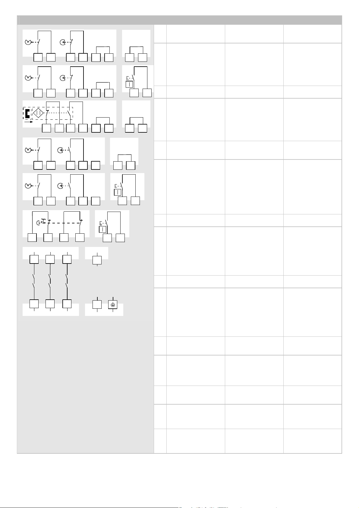
20
Installazione / Instalación / Instalacja
713 23
14 24
A1
A2
L1
(L
+)
(M)
8
S14 S35
4.1
33
34
PE
S33 S34
6.1
S13 S14
5CH1
S23 S24
CH2
S22
S13 S14
4CH1
S23 S24
CH2
S22
S14 S35
1.1
S33 S34
2.1
S13 S14
1CH1
S13 S22
CH2
S23 S24
S13 S14
2CH1
S13 S22
CH2
S23 S24
S13 S14 S23 S24
6
S33 S34
5.1
S14 S35
3.1
S13 S14
3CH1
S13 S22
CH2
S23 S24
Per l'installazione fare
riferimento allo schema
di collegamento.
Instale el aparato de
acuerdo con el esquema
de conexiones.
Podczas instalacji
należy przestrzegać
schematu przyłączeń.
1
Porta di protezione
(aperta)
Comando antivalente,
avvio automatico, rico-
noscimento di cortocir-
cuiti trasversali
Puerta de protección
(abierta)
control no equivalente,
arranque automático,
detección de
cortocircuitos
transversales
Drzwi ochronne
(otwarte)
sterowanie
antywalentne, start
automatyczny,
rozpoznawanie
krosowania
1.1
Ponte avvio automatico
Puente arranque auto-
mático
Mostek startu
automatycznego
2
Porta di protezione
(aperta)
Comando antivalente,
avvio manuale, ricono-
scimento di cortocircuiti
trasversali
Puerta de protección
(abierta)
control no equivalente,
arranque manual,
detección de
cortocircuitos
transversales
Drzwi ochronne
(otwarte)
sterowanie
antywalentne, start
ręczny, rozpoznawanie
krosowania
2.1
Pulsante di reset
(S14/S34 per apparec-
chio CA)
Pulsador de reinicio
(S14/S34 con aparato
CA)
Przycisk reset
(S14/S34 w urządzeniu
AC)
3
Porta di protezione
(chiusa)
Comando antivalente
mediante interruttori
magnetici codificati,
avvio automatico, rico-
noscimento di cortocir-
cuiti trasversali
Puerta de protección
(cerrada)
control no equivalente
mediante conmutador
magnético codificado,
arranque automático,
detección de cortocir-
cuitos transversales
Drzwi ochronne
(zamknięte)
sterowanie
antywalentne przez
kodowany przełącznik
magnetyczny, start
automatyczny,
rozpoznawanie
krosowania
3.1
Ponte avvio automatico
Puente arranque auto-
mático
Mostek startu
automatycznego
4
Porta di protezione
(aperta)
Comando equivalente,
avvio automatico, rico-
noscimento di cortocir-
cuiti trasversali (S22
non collegato)
Puerta de protección
(abierta)
control equivalente,
arranque automático,
detección de
cortocircuitos
transversales (S22
desconectada)
Drzwi ochronne
(otwarte)
sterowanie
ekwiwalentne, start
automatyczny,
rozpoznawanie
krosowania (S22
niepodł
ą
czony)
4.1
Ponte avvio automatico
Puente arranque auto-
mático
Mostek startu
automatyczne
g
o
5
Porta di protezione
(aperta)
Comando equivalente,
avvio manuale, ricono-
scimento di cortocircuiti
trasversali (S22 non
collegato)
Puerta de protección
(abierta)
control equivalente,
arranque manual,
detección de
cortocircuitos
transversales (S22
desconectada)
Drzwi ochronne
(otwarte)
sterowanie
ekwiwalentne, start
ręczny, rozpoznawanie
krosowania (S22
niepodłączony)
5.1
Pulsante di reset
(S14/S34 per apparec-
chio CA)
Pulsador de reinicio
(S14/S34 con aparato
CA)
Przycisk reset
(S14/S34 w urządzeniu
AC)
6
A
rresto d'emergenza
A due canali, avvio ma-
nuale, riconoscimento di
cortocircuiti trasversali
Parada de emergencia
dos canales, arranque
manual, detección de
cortocircuitos transver-
sales
Wyłącznik awaryjny
dwukanałowy, start
ręczny, rozpoznawanie
krosowania
6.1
Pulsante di reset
(S14/S34 per apparec-
chio CA)
Pulsador de reinicio
(S14/S34 con aparato
CA)
Przycisk reset
(S14/S34 w urządzeniu
AC)
7
Circuiti di abilitazione
3contatti di chiusura, a
conduzione forzata
Líneas de contactos de
habilitación
3contactos NA, de
accionamiento forzado
Ś
cieżki prądów
zwalniających
3 zestyki zwierne,
wymuszone
8
Tensione di alimenta-
zione
PE solo per apparecchio
CA
Tensión de
alimentación
PE solo para aparatos
CA
Napięcie zasilające
PE tylko w
urządzeniach AC
This manual suits for next models
1
Table of contents
Languages:
Other Wieland Relay manuals


