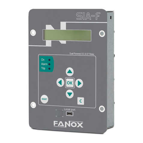
FANOX SIA F User manual

www.fanox.com Rev. 01 2/17
1. MODBUS RTU PROTOCOL............................................................................................3
1.1. Modbus RTU pachage format........................................................................................4
1.2. Function Codes...............................................................................................................4
1.3. Exceptions Responses ..................................................................................................5
1.4. Data type..........................................................................................................................5
1.5. General Memory Map .....................................................................................................7
1.5.1. States Map ...................................................................................................................7
1.5.2. Measurements Map....................................................................................................12
1.5.3. Settings Map ..............................................................................................................12
1.6. Command List...............................................................................................................16
1.7. Setting-up the session: Password and access levels ..............................................16
1.8. Example of Modbus Frames........................................................................................16

www.fanox.com Rev. 01 3/17
1. MODBUS RTU PROTOCOL
Communication parameters are:
Modbus RTU:
•Address and Baudrate
•8 data bits
•No parity
•1 stop bit
This document describes the steps to follow to read and write data on the SIA-F relay, as per the Modbus
protocol. This memory map is only valid for one piece of equipment and one version of the memory. The
positions of existing objects in the memory remain fixed from one version to the next, but new objects will
naturally have new addresses which will, in turn, remain fixed in future versions. The memory map is
described further on.
The standard Modbus protocol is used, so any program or PC can communicate easily with the equipment.
The SIA-F always acts as a slave, which means that it never initiates communications. The master is
always responsible for initiating communications.
Only a subset of the Modbus functions is implemented:
•Reading function 3.
•Writing function 16.
The MODBUS/RTU protocol is independent from the hardware. Therefore, the physical layer can exist in
different hardware configurations: RS232, RS485, fibre optic or Ethernet.
Specifically, the relay has a front RS232 port and, as an option, a rear RS485 port. The data stream in any
of the configurations is “half-duplex”.er
Each byte of data is transmitted asynchronously and is made up of: 1 start bit, 8 data bits, 1 stop bit and
1 parity bit, if this is how it is programmed. Therefore, the data has 10 or 11 bits, depending on whether it
includes parity.
If the relay only offers with Modbus on the front port, the address (1 to 247) is configurable but the rest of
the paarmeters are fixed and equal to: baudrate 19200, No parity and stop bit 1.
If the relay offers RS485 Modbus protocol the the address (1 to 247) and the baudrate (4800, 9600, 19200
or 38400) con be but the rest of the parameters are fixed: without parity and with 1 stop bit.
The master must know the address of the slave that it is going to communicate with. No unit will act on
requests from the master if the message is not addressed to them. The exception is when the 0 address,
or “broadcast” address, is used, in which case the relay will act but will not send an answer of any type.
Communications are made in packages or frames, which are groups of data that are sent asynchronously.
The master transmits a frame to the slave, and the slave then replies with another frame (except in the
case of “broadcast” messages).
The end of the frame is marked by a dead time or silence time in the communication medium. The length
of this time of silence varies depending on the transmission speed, as it is equivalent to 3 characters.
The following table shows the generic package format that is valid for transmission and reception.
However, each function has its own peculiarities, as will be described further on.

www.fanox.com Rev. 01 4/17
1.1. Modbus RTU pachage format
CUSTOMER
ADDRESS
1 byte
Each device on a communication bus must have a unique address, otherwise two
different units could reply simultaneously to the same request. All ports of the
relay will use this address which can be set a value between 1 and 247. When the
master transmits a frame with the slave address to 0 indicates a Broadcast. All
the slaves in the communications bus will carry out the requested action, but no
one will reply to the master. The Broadcast will only be accepted to write, as it
makes no sense to make a read request in the Broadcast, as no one will reply this
request.
FUNCTION
CODE
1 byte
This is one of the function codes supported by the equipment. In this case, the
only function codes supported are 3 to read and 16 to write. When the slave has
to reply with an exception one of these frames, it is indicated by putting 1 in the
most important bit of the correspondent function. Thus, an exception for the
function 3, will be indicated with a 83 as a function code; and an exception for the
function code 16 or 0x10 in hexadecimal, will be indicated with an 0x90.
DATA
N bytes
This part consists of a variable number of bytes, depending on the function code.
It may include: addresses, data lengths, settings, commands or exception codes
sent by the user.
CRC
2 bytes
Control code of two bytes. The ModBus/RTU includes a 16-bit CRC in each
frame, to detect errors. If the slave detects an erroneous frame, based on a CRC
that is not correct, it won’t take any action, nor will reply anything to the master.
The management of the CRC is LSB-MSB.
DEAD TIME
Necessary time
to transmit 3,5
Bytes
A frame is terminated when nothing is received for a period of 3,5 bytes. It means:
15 ms at 2400 bps
2 ms at 19200 bps
...etc.
1.2. Function Codes
HEX
DEC
CODE
MODBUS NAME
DEFINITION
COMMENT
0x03
3
Read Holding
Registers
Reading of Any Value
This function allows the master to read 1 or
more consecutive addresses of a relay. The
registers always are of 16 bits, with the most
important byte at first. The maximum number
of registers to be read in a package are 60.
HEX
DEC
CODE
MODBUS NAME
DEFINITION
COMMENT
0x10
16
Preset Multiple
Registers
Script
This function allows to write one or more
registers that represent one or more settings.
The registers are values of 2 bytes of length,
transmitted with the most important byte at
first. The maximum number of registers to be
written in a package is 60.

www.fanox.com Rev. 01 5/17
1.3. Exceptions Responses
The error codes defined by the ModBus protocol are as follows:
01
ILLEGAL FUNCTION
The slave does not support any function with the function code received in
this message.
02
ILLEGAL DATA ADDRESS
The master is trying to do an operation in a wrong address.
03
ILLEGAL DATA VALUE
The slave has detected that the value sent by the master is not valid.
04
SLAVE DEVICE FAILURE
Indicates an error occurred in the slave while trying to execute the request
of the master.
05
ACKNOWLEDGE
Generic recognition.
06
SLAVE DEVICE BUSY
The slave is busy and unable to perform the required operation.
07
NEGATIVE ACKNOWLEDGE
Generic non-recognition.
When the data format takes up more than one BYTE, the most important BYTE is sent through the
communications first, and the least important BYTE is sent last.
1.4. Data type
TYPE
LENGTH
DESCRIPTION
UCHAR
1/2
Integer without sign of 1 byte
BYTE
1/2
Integer with sign of 1 byte
BIT16
1
Gathered bits type, groups of 16.
E. g.: 0x1A41 = 0001101001000001b
BIT32
2
Gathered bits type, groups of 32.
ENUM
1
Integer without sign of 16 bits. Each of the possible values of the integer will have
a correspondence in the auxiliary list of the database. This list is the
correspondence chain which must be shown for each of the values. Memory will
only receive an integer value.
E. g.: 0, 1 Correspondence to “CLOSED”, “OPEN”
DENUM
2
Integer without sign of 32 bits
UINT
1
Integer without sign of 2 bytes
INT
1
Integer with sign of 2 bytes
LONG
2
Integer without sign of 4 bytes

www.fanox.com Rev. 01 6/17
DWORD
2
Integer with sign of 4 bytes
FLOAT
INVERSE
2
Number in FLOAT INVERSEing decimal point “FLOAT INVERSE” of 4 bytes
ASCIIxx
xx/2
String: In length variable character chain. Final of String marked with ‘\0’.
E. g.: “ABC” 0x41x42x43x00....
MILIS
3
Minutes (passed since 00:00 of 1/1/2000) (LONG). milliseconds (UINT)
FH
5
Year(UINT).month(UCHAR).day(UCHAR).hour(UCHAR).minutes(UCHAR).second
s(UCHAR).hundredth(UCHAR).thousandth(UINT)
CONT
13
Directory (UINT).Value(DWORD).Description(ASCII20)
EVENT
9
Criteria Directory (UINT).Event Identifier(UINT).Value(UINT).Associated
Measure(UINT).Date and Time(FH)
EVENTO
10
Antiquity (UINT).Event (EVENT)
CCRIT
6
Criteria Number (UINT). Criteria Directory(UINT).Descriptive text(ASCII8)
PEST
61
Number of States (UINT). Protection State-1(BIT16). … Protection State-60(BIT16)
PCRIT
61
Number of Criteria (UINT). Index of Criteria-1(UINT). … Index of Criteria-60(UINT).
CMED
8
Number of Measure (UINT). Descriptive text(ASCII7).Unit(ASCII3).Primary
Unit(ASCII5).Number of decimals(UCHAR)
GAJU
61
Number of Groups (UINT). Index of the Criteria-1(UINT).Index of the first setting of
the Criteria-1(UINT). … Index of the Criterion-30(UINT). Index of the first setting of
the Criteria-30(UINT).
ENUM TRIP
VOLT
1
Integer without sign of 16 bits.
E. g.: 0, 1, 2 Correspondence to “12V”, “17V”, “22V”
When the data format takes up more than one BYTE, the most important BYTE is sent through the
communications first, and the least important BYTE is sent last.

www.fanox.com Rev. 01 7/17
1.5. General Memory Map
Function
Description
Start
address
Number of
registries
Format
Reference
16
Write the Directory of Event
1
1
UINT
16
Write the number of the Setting List
6
1
UINT
03
Read of Model and Version
100
44
ASCII88
16
Write access code
168
2
UCHAR4
See Passwords and
Access Levels
03 & 16
Date and Time
170
5
FH
16
Selection of Command
200
1
UINT
See Commands map
16
Confirmation of Command
201
1
UINT
See Commands map
03 & 16
Counters
202
2
CONT
Opennings Number
03 & 16
Counters
204
2
CONT
Accumulated
Amperes
03
Serial number
252
2
LONG
03
Equipment identifier
254
44
ASCII88
03
Read and Delete the oldest Event
400
11
EVENTO2
See States map
(Event Number)
03
One event reading
410
11
EVENTO2
See States map
(Event Number)
16
Delete All Events
420
1
dummy
1.5.1. States Map
The function code implemented to State reading is is 0x03 (Read Holding Registers)
Address
Description
Bit
Event NO
Status
Associated
Measurement
500
General
00
1
Trip
Imax (A)
01
2
External Trip
-
03
7
50 Hz
-
04
8
Trip Block Enable
-
05
16
Measure Error
-
06
17
Ready
07
19
Settings Changed
-
08
21
Set Date/Time
-

www.fanox.com Rev. 01 8/17
09
22
Local Activity
-
10
23
Factory Settings
-
11
24
EEPROM Error
-
12
28
EEPROM Changed
-
13
32
Events Error
-
14
15
Reset
-
Address
Description
Bit
Event NO
Status
Associated
Measurement
8000
Oscilo
-
16
DFR Erased
Address
Description
Bit
Event NO
Status
Associated
Measurement
502
Local COM
00
Local communication
01
HMI Activity
17
2
Open Breaker
18
3
Close Breaker
23
9
Reset
25
8
Reset thermal image
Address
Description
Bit
Event NO
Status
Associated
Measurement
504
50
00
01
50 Phase A Pickup
IA (A)
01
02
50 Phase B Pickup
IB (A)
02
03
50 Phase C Pickup
IC (A)
03
04
50 Pickup
Imax (A)
08
05
50 Phase A Trip
IA (A)
09
06
50 Phase B Trip
IB (A)
10
07
50 Phase C Trip
IC (A)
11
08
50 Trip
Imax (A)

www.fanox.com Rev. 01 9/17
Address
Description
Bit
Event NO
Status
Associated
Measurement
506
51
00
01
51 Phase A Pickup
IA (A)
01
02
51 Phase B Pickup
IB (A)
02
03
51 Phase C PIckup
IC (A)
03
04
51 Pickup
Imax (A)
08
05
51 Phase A Trip
IA (A)
09
06
51 Phase B Trip
IB (A
10
07
51 Phase C Trip
IC (A)
11
08
51 Trip
Imax (A)
Address
Description
Bit
Event NO
Status
Associated
Measurement
508
50G
04
01
50G Pickup
IN (A)
12
02
50G Trip
IN (A)
Address
Description
Bit
Event NO
Status
Associated
Measurement
510
51G
04
01
51G Pickup
IN (A)
12
02
51G Trip
IN (A)
Address
Description
Bit
Event NO
Status
Associated
Measurement
512
Inputs (*)
00
17
Input 1
-
01
18
Input 2
-
Address
Description
Bit
Event NO
Status
Associated
Measurement
514
Outputs (*)
00
01
Trip Output
-
01
02
Output 1
-
02
03
Output 2
-
Address
Description
Bit
Event NO
Status
Associated
Measurement
516
Trip Block (*)
00
01
Phase A Block
IA (A)
01
02
Phase B Block
IB (A)
02
03
Phase C Block
IC (A)
03
04
Phase Block
Imax (A)

www.fanox.com Rev. 01 10/17
Address
Description
Bit
Event NO
Status
Associated
Measurement
518
50BF (*)
00
01
50BF Pickup
Imax (A)
01
02
50BF Trip
Imax (A)
Address
Description
Bit
Event NO
Status
Associated
Measurement
520
52
00
01
52 Start
-
01
02
52 Error
-
02
03
52 Open
Opening Time
03
04
52 Opening time
-
04
05
52 Opening Error
Opening Time
05
06
52 Closed
Closing time
06
07
52 Closing time
-
07
08
52 Closing Error
Closing time
08
09
52 Max. Number of openings
-
09
10
52 Max. Accumulated amperes
(I2t).
-
10
11
52 Max. openings/Time
-
11
12
Contact 52a
-
12
13
Contact 52b
-
Address
Description
Bit
Event NO
Status
Associated
Measurement
524
Remote COM
00
-
Remote communication
None
17
02
Open Breaker
None
18
03
Close Breaker
None
23
09
Reset
25
08
Reset thermal image
None
Address
Description
Bit
Event NO
Status
Associated
Measurement
522
49 (*)
04
01
49 Alarm
Thermal Image (%)
12
02
49 Trip
Thermal Image (%)

www.fanox.com Rev. 01 11/17
Address
Description
Bit
Event NO
Status
Associated
Measurement
534
CLP
00
-
CLP Disable
-
01
-
52 Closed
-
02
-
52 Open
-
03
-
52 Definitive open
-
04
-
Close Cold Load
-
05
-
Open Cold load
-
12
02
Cold Load Pickup
-
Address
Description
Bit
Event NO
Status
Associated
Measurement
538
Leds
00
-
Led 1
-
01
-
Led 2
-
02
-
Led 3
-
Address
Description
Bit
Event NO
Status
Associated
Measurement
540
Logic
06
18
52a
-
07
19
52b
-
08
22
External trip
-
09
07
50BF start
-
10
08
Fault start
-
11
20
50 block
-
12
21
50N/G block
-
13
23
Reset
-
14
-24
Active group 1
-
15
-25
Active group 2
-

www.fanox.com Rev. 01 12/17
1.5.2. Measurements Map
Address
Description
Format
300
Phase A current IA
FLOAT INVERSE
302
Phase B current IB
304
Phase C current IC
306
Neutral current IN
308
Thermal Image TI
310
Maximum phase current IMAX
1.5.3. Settings Map
Settings
Address
Description
Format
Enumeration
Generals
600 (*)
Identification
ASCII20
-
800 (**)
610 (*)
Frequency
DENUM
0 → 60 Hz
1 → 50 Hz
810 (**)
612 (*)
Serial Number
LONG
-
812 (**)
614 (*)
Language
DENUM
0 → English
1 → Spanish
2 → Depends on Relay model
814 (**)
616 (*)
Active Setting Group
LONG
-
816 (**)
618 (*)
CT Phase Ratio
FLOAT INVERSE
-
818 (**)
620 (*)
CT Neutral Ratio
FLOAT INVERSE
820 (**)
622 (*)
Local COM Address
LONG
-
822 (**)
624 (*)
Password
ASCII4
-
824 (**)
626 (*)
Remote COM Address
LONG
-
826 (**)
628 (*)
Remote Baud Rate
DENUM
0 → 4800 Bd
1 → 9600 Bd
2 → 19200 Bd
3 → 38400 Bd
828 (**)

www.fanox.com Rev. 01 13/17
(*) Read/Write Address (FC = 03 / 16).
(**) Address for Confirmation (FC = 16)
Settings
Address
Description
Format
Enumeration
51
636 (*)
Function Enable
DENUM
0 → Disable
1 → Enable
836 (**)
638 (*)
Curve Type
DENUM
0 → IEC Inverse
1 → IEC Very Inverse
2 →IEC Extremely Inverse
3 → Defined Time
4 → IEEE Inverse
5 →IEEE Very Inverse
6 → IEEE Extremely Inverse
7 → IEC Long Time Inverse
838 (**)
640 (*)
Time Dial (TMS)
FLOAT INVERSE
-
840 (**)
642 (*)
Tap
FLOAT INVERSE
-
842 (**)
644 (*)
Time Delay
FLOAT INVERSE
-
844 (**)
Settings
Address
Description
Format
Enumeration
50G
646 (*)
Function Enable
DENUM
0 → Disable
1 → Enable
846 (**)
648 (*)
Tap
FLOAT INVERSE
-
848 (**)
650 (*)
Time Delay
FLOAT INVERSE
-
850 (**)
(*) Read/Write Address (FC = 03 / 16).
(**) Address for Confirmation (FC = 16)
Settings
Address
Description
Format
Enumeration
50
630 (*)
Function Enable
DENUM
0 → Disable
1 → Enable
830 (**)
632 (*)
Tap
FLOAT INVERSE
-
832 (**)
634 (*)
Time Delay
FLOAT INVERSE
-
834 (**)

www.fanox.com Rev. 01 14/17
Settings
Address
Description
Format
Enumeration
51G
652 (*)
Function Enable
DENUM
0 → Disable
1 → Enable
852 (**)
654 (*)
Curve Type
DENUM
0 → IEC Inverse
1 → IEC Very Inverse
2 →IEC Extremely Inverse
3 → Defined Time
4 → IEEE Inverse
5 →IEEE Very Inverse
6 → IEEE Extremely Inverse
7 → IEC Long Time Inverse
854 (**)
656 (*)
Time Dial (TMS)
FLOAT INVERSE
-
856 (**)
658 (*)
Tap
FLOAT INVERSE
-
858 (**)
660 (*)
Time Delay
FLOAT INVERSE
-
860 (**)
Settings
Address
Description
Format
Enumeration
49
662 (*)
Function Enable
DENUM
0 → Disable
1 → Enable
862 (**)
664 (*)
Tap
FLOAT INVERSE
-
864 (**)
666 (*)
Heating Constant 𝜏
LONG
-
866 (**)
668 (*)
Cooling Constant
LONG
-
868 (**)
670 (*)
Alarm Level
LONG
-
870 (**)
Settings
Address
Description
Format
Enumeration
Trip Block
672 (*)
Function Enable
DENUM
0 → Disable
1 → Enable
872 (**)
674 (*)
Tap
FLOAT INVERSE
-
874 (**)
Settings
Address
Description
Format
Enumeration
50BF
676 (*)
Function Enable
DENUM
0 → Disable
1 → Enable
910 (**)
678 (*)
Time Delay
FLOAT INVERSE
-
912 (**)
(*) Read/Write Address (FC = 03 / 16).
(**) Address for Confirmation (FC = 16)

www.fanox.com Rev. 01 15/17
Settings
Address
Description
Format
Enumeration
52
680 (*)
Max Number of Openings
LONG
-
880 (**)
682 (*)
Max Accumulated
Amperes
LONG
-
882 (**)
684 (*)
Opening Time
FLOAT INVERSE
-
884 (**)
686 (*)
Closing Time
FLOAT INVERSE
-
886 (**)
688 (*)
Excessive Repeated
Openings
LONG
-
888 (**)
690 (*)
Repetitive Openings/Time
FLOAT INVERSE
-
890 (**)
Settings
Address
Description
Format
Enumeration
CLP
736 (*)
Function Enable
DENUM
0 → Disable
1 → Enable
936 (**)
738 (*)
Active Settings Group
LONG
-
938 (**)
740 (*)
No Load Time
FLOAT INVERSE
-
940 (**)
742 (*)
Cold Load Time
FLOAT INVERSE
-
942 (**)
(*) Read/Write Address (FC = 03 / 16).
(**) Address for Confirmation (FC = 16)

www.fanox.com Rev. 01 16/17
1.6. Command List
Index
Format
Description
2
UINT16
Open Breaker
3
UINT16
Close Breaker
8
UINT16
Reset Thermal Image
9
UINT16
Reset
1.7. Setting-up the session: Password and access levels
Users must identify themselves with a password in order to pick up communications and to change the device
settings or configuration using the HMI.
By default, the password is 5555 and it can be changed from general settings menu.
1.8. Example of Modbus Frames
Writing the access password “5555” to equipment no. 1
Address
Function
H Pickup
Address
L Pickup
Address
Number of
H Registers
Number of
L Registers
Number
of
Bytes
Password
Checksum
H
Checksum L
0x01
0x10
0x00
0xA8
0x00
0x02
0x04
0x35
0x35
0x35
0x35
0x30
0xF4
And the SIA-F will reply OK:
Address
Function
H Pickup
Address
L Pickup
Address
Number
of H
Registers
Number of L
Registers
Checksum
H
Checksum
L
0x01
0x10
0x00
0xA8
0x00
0x02
0xC0
0x28
Table of contents
Other FANOX Relay manuals

FANOX
FANOX SIA B User manual

FANOX
FANOX SIA-B Series User manual

FANOX
FANOX D30 User manual

FANOX
FANOX SIL-A A Series User manual

FANOX
FANOX SIA-B Standard Series User manual

FANOX
FANOX C Series User manual

FANOX
FANOX SIA-B Standard CTs User manual

FANOX
FANOX C 9 Guide

FANOX
FANOX SIL B User manual

FANOX
FANOX SIA-F Series User manual