ZIEHL SW32V User manual

ZIEHL industrie –elektronik GmbH + Co KG
Daimlerstr.13, 74523 Schwäbisch Hall, Germany
+ 49 791 504-0, [email protected]e, www.ziehl.de
Temperature Relays and MINIKA® Mains Monitoring Digital Panelmeters MINIPAN® Switching Relays and Controls Measuring Transducers Grid- and Plant Protection
Operating Manual SW32V
updated: 2017-05-03/Fu
from Firmware: 0.13
SW32V 11820-0701-01 Seite
1
/ 22 www.ziehl.de
Voltage relay for monitoring direct, alternating and three-phase networks for overvoltage and/or
undervoltage
from Firmware 0.13
Pr5+6 with default settings for grid and plant protection according to bdew directive (medium voltage)

SW32V 11820-0701-01 Page
2
/ 22 www.ziehl.de
Table of contents
1Display and controls .............................................................................................................................. 3
2Factory settings and software version ................................................................................................. 4
3Adjustment values table BDEW June 2008, acc 3.2.3.3-1, Medium Voltage Pr 5+6........................... 5
4Application and brief description.......................................................................................................... 5
5Summary of the functions ..................................................................................................................... 5
6Connection diagram and example grid- and plant protection............................................................. 6
7Important Notice..................................................................................................................................... 7
8Mounting................................................................................................................................................. 7
9Detailed description ............................................................................................................................... 8
Description of the connections....................................................................................................... 8
Functional characteristics .............................................................................................................. 8
10 Commissioning....................................................................................................................................... 9
Program setup............................................................................................................................... 9
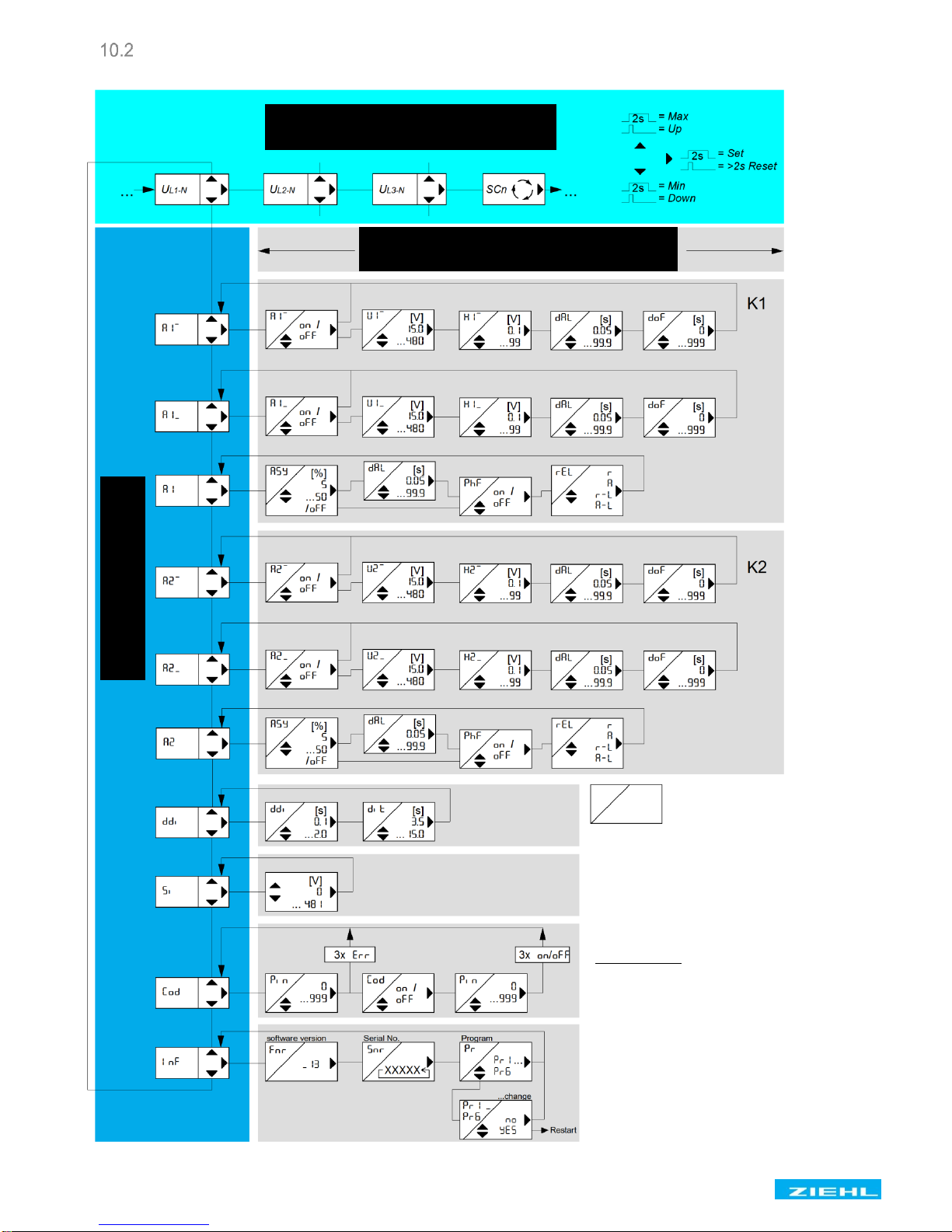
Control chart Pr 1 + 5, 3AC with N.............................................................................................. 10
Control chart Pr 2 + 6, 3AC without N.......................................................................................... 11
Control chart Pr 3, 1AC with N..................................................................................................... 12
Control chart Pr 4, DC ................................................................................................................. 13
Description of the parameters...................................................................................................... 14
Display mode (last decimal point off) ........................................................................................... 15
Menu mode (last decimal point on).............................................................................................. 15
Configuration mode (last decimal point flashes)........................................................................... 15
Configuring the alarms............................................................................................................. 16
Configure Delay Display, Display Time .................................................................................... 17
Simulation................................................................................................................................ 17
Code lock................................................................................................................................. 18
Possible indications in display.................................................................................................. 19
11 Maintenance and repair........................................................................................................................ 20
12 Troubleshooting and measures .......................................................................................................... 20
13 Technical Data...................................................................................................................................... 21
14 Mounting type V4.................................................................................................................................. 22

SW32V 11820-0701-01 Page
3
/ 22 www.ziehl.de
1 Display and controls
1
Last decimal point (red)
Off
Display mode
Illuminated
Menu mode
Flashes
Configuration mode
2
LEDs relay status (yellow)
OFF
Relay is released
ON
Relay operating
3
LED Asymmetry (red)
OFF
Asymmetry surge limit not exceeded
ON, 8A 18or 8A 28
Asymmetry limit exceeded
FLASHES, 8A1L8or 8A2L8
Ready for reset after exceeding the limit
FLASHES, 8A 18or 8A 28
Reset delay 8dof8counting down
4
LEDs voltage limit undercut / exceeded (red)
ON, 8A 18or 8A 28
Limit undercut / exceeded
FLASHES, 8A1L8or 8A2L8
Ready for reset after undercutting / exceeding the limit value
FLASHES, 8A 18or8A 28
Reset delay 8dof 8counting down
OFF
Limit value not undercut / exceeded
5
LED phase sequence (red)
OFF
Phase sequence correct (rotating clockwise) or 8off8
ON, 8A 18or 8A 28
Phase sequence error (rotating counter-clockwise)
FLASHES, 8A1L8or 8A2L8
Ready for reset after phase sequence error
6
Up / Down key (in display mode, normal state)
Press briefly
Change into the menu mode (see Point 8.5)
Press for > 2 s
Displays the MAX (Up) and MIN (Down) measurement; additionally
pressing the Set key for ≥ 2 s deletes the saved value
7
Set/Reset key (in display mode, normal state)
Press briefly
Displays the next measurement
Press for > 2 s
Reset after locked alarm (manual restart)
(not possible if DoF Reset delay is counting down)
Press for > 4 s
Displays the program, e.g. 8Pr18
Press for > 10 s
Displays the software version e.g. 80008
8
LEDs measurement allocation (yellow)
LEDs
Measurement
Lx and N ON
Voltage value (L1 against N, L2 against N, L3 against N)
Lx and Ly ON
Voltage value (L1 against L2, L2 against L3, L1 against L3)
9
Digital display 3-digits (red)
Depending on the program display, actual voltage, frequency
Displays the alarm messages, e.g. 8A 18, 8a2L8,…
Displays the errors with error code e.g. 8Er98

SW32V 11820-0701-01 Page
4
/ 22 www.ziehl.de
2 Factory settings and software version
When changing programs, all parameters are reset to the factory settings.
Menu
Parameter / Unit
Default settings
Users Data
3AC+N
3AC
1AC
DC
3AC+N
3AC
Pr1
Pr2
Pr3
Pr4
Pr5
Pr6
A1,
A1, (Alarm)
on
on
on
on
on
on
U1, (upper limit)
V
253
440
253
242
264
115
H1, (Hysteresis)
V
5.0
5.0
5.0
5.0
3.0
1.0
dal (Alarm delay)
s
0.10
0.10
0.10
0.10
0.10
0.10
dof (Reset delay)
s
0
0
0
0
60
60
A1_
A1_ (Alarm)
on
on
on
on
oFF
off
U1_ (lower limit)
V
196
340
196
198
104
45.0
H1_ (Hysteresis)
V
5.0
5.0
5.0
5.0
2.0
1.0
dal (Alarm delay)
s
0.10
0.10
0.10
0.10
0.30
0.30
dof (Reset delay)
s
0
0
0
0
60
60
A1
asy (Asymmetry)
%
off
off
off
off
dal (Alarm delay)
s
0.10
0.10
0.10
0.10
Phf (Phase sequence)
off
off
off
off
rel (Relay function)
r
r
r
r
r
r
A2,
A2, (Alarm)
on
on
on
on
on
on
U2, (upper limit)
V
253
440
253
242
249
108
H2, (Hysteresis)
V
5.0
5.0
5.0
5.0
3.0
1.0
dal (Alarm delay)
s
0.10
0.10
0.10
0.10
60.0
60.0
dof (Reset delay)
s
0
0
0
0
60
60
A2_
A2_ (Alarm)
on
on
on
on
on
on
U2_ (lower limit)
V
196
340
196
198
184
80.0
H2_ (Hysteresis)
V
5.0
5.0
5.0
5.0
3.0
1.0
dal (Alarm delay)
s
0.10
0.10
0.10
0.10
2.70
2.70
dof (Reset delay)
s
0
0
0
0
60
60
A2
asy (Asymmetry)
%
off
off
off
off
dal (Alarm delay)
s
0.10
0.10
0.10
0.10
Phf (Phase sequence)
off
off
off
off
rel (Relay function)
r
r
r
r
r
r
ddi
ddi (Display delay)
s
0.5
0.5
0.5
0.5
0.5
0.5
dit (Display duration)
s
3.5
3.5
3.5
3.5
Si
U (Voltage)
V
230
400
230
220
230
100
Cod
On /off
off
off
off
off
off
off
pin (Pin code)
504
504
504
504
504
504
Inf
fnr Firmware version
_13
_13
_13
_13
_13
_13
snr Serial number
xxxxx
xxxxx
xxxxx
xxxxx
xxxxx
xxxxx
Pr Program
1
2
3
4
5
6
Display the program: Press the "Set" key for 4 s in the display mode.
Display the software version: Press the "Set" key for 10 s in the display mode.

SW32V 11820-0701-01 Page
5
/ 22 www.ziehl.de
3 Adjustment values table BDEW June 2008, acc 3.2.3.3-1,
Medium Voltage Pr 5+6
Function
Adjustment range
of the protective
relay
Default settings
Voltage increase protection U>>
1.00 –1.30 Un
1.15 Un
100 ms
Voltage increase protection U>
1.00 –1.30 Un
1.08 Un
60 s
Voltage decrease protection U<
0.15 –1.00 Un
0.80 Un
2.7 s
Voltage decrease protection U<< *
0.15 –1.00 Un
0.45 Un
300 ms
* Not enabled in as delivered condition
4 Application and brief description
The SW32V voltage relay is a high-quality voltage monitor with a large measurement range for monitoring
direct, alternating and three-phase networks for overvoltage and/or undervoltage. In three-phase current
networks, phase symmetry and phase sequence can be monitored in addition.
The limits are set in volts. That allows using the unit with various rated voltages.
The digital display is used to display the measurements and to precisely set limits, response times and
functions.
5 Summary of the functions
For use as a voltage monitor in energy generation and distribution plants, especially in-plant systems such
as PV plants or combined heat and power plants.
Voltage monitoring in machines and plants to prevent errors, damage or failures in sensitive equipment or
devices.
•Voltage monitoring in direct current networks DC 10.0…600 V
•Voltage monitoring in alternating current networks AC 15.0…480 V
•Voltage monitoring in three-phase current networks with//without N up to 3AC 830 V, asymmetrical
and phase failure monitoring connectible
•Preset programs for grid- and plant protection according to bdew directive (medium voltage)
•Real root mean square measurement (for AC, both half waves)
•2 Alarms/output relays, 1 each change-over contact
•Alarm and reset delay for every limit value can be individually set
•Setting of limits and hysteresis in volts
•Measurement value simulation to check the settings
•Code lock can be enabled
•Control voltage AC/DC 24-270 V
•Distributor housing for panel mounting, 4 TE (70 mm), front-to-back size 55 mm
•Mounting on 35 mm mounting rails DIN EN 60715

SW32V 11820-0701-01 Page
6
/ 22 www.ziehl.de
6 Connection diagram and example grid- and plant protection
3 phase with N (Pr1) 3 phase without N (Pr2)
1 phase (Pr3)
DC (Pr4) grid- and plant protection
Alarm 1 Alarm 2
Alarm 1 Alarm 2
Alarm 1 Alarm 2

SW32V 11820-0701-01 Page
7
/ 22 www.ziehl.de
7 Important Notice
WARNING
Hazardous electrical voltage!
Can lead to electric shock and burns.
Before starting work, switch plant and device voltage-free.
The flawless and safe operation of a device requires that it is shipped and stored appropriately,
professionally installed and put into operation and operated according to its intended use.
Only people who are familiar with the installation, commissioning and operation and who have
qualifications corresponding to their job are permitted to work on the device. They must comply with the
contents of the operating instructions, the notices attached to the device and the relevant safety
regulations for constructing and operating electrical plants.
The devices are built and certified in accordance with EN 60255 and leave the factory in a safe and
technically flawless condition. To maintain this state you must comply with the safety regulations indicated
with "Caution" in the operating instructions. Non-compliance with the safety regulations can lead to death,
bodily injury or property damage on the device itself and on other devices and equipment.
If the information in the operating instructions is insufficient at any time, please contact us directly or
contact the representation responsible for you.
Instead of the industrial norms and stipulations stated in the operating instructions and applicable in
Europe, you must comply with the valid and applicable regulations in the country of utilisation if the device
is used outside of the area of application.
Caution! If the operating current execution is programmed for all relays, a failure
of the control voltage or the device will not be detected.
When using as a monitoring device, the operator must ensure that this error is
detected through periodic performance tests.
We recommend programming and correspondingly evaluating at least one relay
in closed-circuit (idle) current execution.
8 Mounting
The device can be mounted:
•Distribution board or switch cabinet on 35 mm rails according to EN 60715
Comply with the maximum permissible temperature when installing in a switch cabinet. Ensure
sufficient clearance to other devices or heat sources. If cooling is inhibited, e.g., through close
proximity to devices with increased surface temperature or interference with the cooling-air
current, the permissible ambient temperature is decreased.
Caution!
Before you apply mains voltage to the device, make sure that the permissible control
voltage Uson the side rating plate matches the mains voltage connected to the device!
!
!

SW32V 11820-0701-01 Page
8
/ 22 www.ziehl.de
9 Detailed description
Description of the connections
Connection
Function
A1 and A2
Control voltage Us, see Technical Data
11, 12, 14
Relay K1, menu item 8A1:8, 8a1_.8
21, 22, 24
Relay K2, menu item 8A2:8, 8a2_.8
nc
Not used
N (-)
Neutral conductor (DC -)
L1 (+)
Phase L1 (DC +)
L2
Phase L2
L3
Phase L3
Functional characteristics
Explanation
Display mode 8Scn8
In programs with multiple display values, there is a switchover into the
automatic display mode after the last display value, which is indicated
by the display of 8scn8.
All measurements will now be displayed cyclically for the time set in
8dit8.
MIN / MAX values
All min and max values are saved zero-voltage maintained (non
volatile). After triggering, the trip value is still available after the control
voltage is switched off.
Reset delay
After applying the control voltage, for K1 the reset delay set in 8A1_8
and for K2 the reset delay set in 8A2_8counts down. All alarms,
excepting during false phase sequence, are suppressed during this
time. During this time, the relay remains dropped out, which excludes
a temporary line fault upon starting.
Reset
Use the Reset key or interrupt the control voltage for > 5 s (comply
with reset delay)

SW32V 11820-0701-01 Page
9
/ 22 www.ziehl.de
10 Commissioning
Program setup
The suitable program must be set on the SW32V in accordance with the application (see table). That is
taken care of during commissioning.
Pr
Connection
preset for
rated voltage
Alarm1 (K1)
Alarm2 (K2)
*1
3 AC with N
230 V
Voltage + Asymmetry + Phase
sequence
Voltage + Asymmetry + Phase
sequence
2
3 AC without N
400 V
Voltage + Asymmetry + Phase
sequence
Voltage + Asymmetry + Phase
sequence
3
1 AC with N
230 V
Voltage
Voltage
4
DC
220 V
Voltage
Voltage
5
3 AC with N
230 V
acc. to bdew
Voltage + Asymmetry + Phase
sequence
Voltage + Asymmetry + Phase
sequence
6
3 AC without N
100 V
acc. to bdew
Voltage + Asymmetry + Phase
sequence
Voltage + Asymmetry + Phase
sequence
* factory set
Adjustment process:
•Press button 1x display 8Info.8
•Press button 3x display 8Pr 1.8
•Set the program with the buttons
•Press button 1x display 8no.8
•Press button 1x display 8yes.8
•Press button
Device resets and starts with the newly selected program
Hint: When changing programs, all parameters of the selected program are reset to “default settings“ (see
table „Default settings“). Only change the parameters after having selected the correct program.

SW32V 11820-0701-01 Page
10
/ 22 www.ziehl.de
Control chart Pr 1 + 5, 3AC with N
[ ] = Unit
Up/Down simultaneously sets the
value to Zero.
Code-Reset = 2 s Set when mains
are switched on. (Pin = 504)
Error messages:
Err8 = Limit value error
A1: <A1_,A2: <A2_
Err9 = Parameter error
Display flashes
alternating
Configuration mode
Display mode
Menu mode

SW32V 11820-0701-01 Page
11
/ 22 www.ziehl.de
Control chart Pr 2 + 6, 3AC without N
[ ] = Unit
Up/Down simultaneously sets the
value to Zero.
Code-Reset = 2 s Set when mains
are switched on. (Pin = 504)
Error messages:
Err8 = Limit value error
A1: <A1_,A2: <A2_
Err9 = Parameter error
Display flashes
alternating
Configuration mode
Display mode
Menu mode

SW32V 11820-0701-01 Page
12
/ 22 www.ziehl.de
Control chart Pr 3, 1AC with N
[ ] = Unit
Up/Down simultaneously sets the
value to Zero.
Code-Reset = 2 s Set when mains
are switched on. (Pin = 504)
Error messages:
Err8 = Limit value error
A1: <A1_,A2: <A2_
Err9 = Parameter error
Display flashes
alternating
Configuration mode
Display mode
Menu mode

SW32V 11820-0701-01 Page
13
/ 22 www.ziehl.de
Control chart Pr 4, DC
Configuration mode
Display mode
Display flashes
alternating
[ ] = Unit
Up/Down simultaneously sets the
value to Zero.
Code-Reset = 2 s Set when mains
are switched on. (Pin = 504)
Error messages:
Err8 = Limit value error
A1: <A1_,A2: <A2_
Err9 = Parameter error
Menu mode

SW32V 11820-0701-01 Page
14
/ 22 www.ziehl.de
Description of the parameters
Parameter
Display
Explanation
Adjustment range
Alarms
8A1:8
8A2:8
8A1_8
8A2_8
Alarm 1, 2 Overvoltage (voltage increase)
Alarm 1, 2 Undervoltage (voltage decrease)
8on8,8off8
Upper
limit
8U1,8
8U2,8
Upper limit,
8U1:8<8U1_88er88
8U2:8 <8U2_88er88
815.08… 84808
826.08… 88308
810.08… 86008
Lower
limit
8U1_8
8U2_8
Lower limit,
8U1_8>8U1:88er88
8U2_8>8U2:88er88
815.08… 84808
826.08… 88308
810.08… 86008
Hysteresis
upper limit
8H1,8
8H2,8
253 (Limit) - 5(Hysteresis) = 248(Reset value)
80.18… 8998
Hysteresis
lower limit
8H1_8
8H2_8
196 (Limit) + 5(Hysteresis) = 201 (Reset value)
80.18… 8998
Alarm
delay
(delay Alarm)
8dAL8
An alarm is suppressed for the set time
(seconds).
80.058… 899.98
Reset
delay
(delay Off)
8dOF8
Reset is delayed for the set time.
On voltage recovery the control voltage, for K1
the reset delay set in 8A1_8and for K2 the
reset delay set in 8A2_8counts down. All
alarms, excepting during false phase sequence,
are suppressed during this time.
808… 89998
Asymmetry
8asy8
Maximum phase symmetry,
10 (Limit) - 1(Fixed hysteresis) = 9 (Reset
value)
8off8,
858… 8508
Phase
sequence
8phf8
Monitors for clockwise rotating field, alarm will
not be delayed
8on8,8off8
Relay function
8rEL8
Idle current 8r8:Relay is pulled up in good
state (= no alarm) and releases when the alarm
value is reached. Alarm even when the control
voltage is switched off.
Locked 8r-L8:Reset only possible through
Reset
8R8
8A8
8r-L8
8A-L8
Operating current 8a8:Relay has released in
good state and operates (attracts) when the
alarm value has been reached. No alarm when
the control voltage is switched off and during
device faults.
Locked 8A-L8:Reset only possible through
Reset
Delay display
8ddi8
Interval during which the display is updated in
the display mode
80.18… 82.08
Display time
8dit8
Display duration per measurement in the 8scn8
mode
83.58… 815.08

SW32V 11820-0701-01 Page
15
/ 22 www.ziehl.de
Display mode (last decimal point off)
In the display mode, the SW32V is in its normal state; the current voltages are displayed here. In addition,
the alarm messages (e.g. 8a1 8, 8a2L8, …) and error codes (e.g. 8er98) are displayed.
Function key
Set / Reset
Press briefly: Switches over the measurements, after the last
measurement value 8Scn8mode (measurements are cyclically
displayed until Set is pressed briefly)
Press for > 2 s: Resets after locked alarm
(not possible if DoF Reset delay is counting down)
Press for > 4 s: Displays the program, e.g. 8Pr18
Press for > 10 s: Displays the software version e.g. 80-58
Function key
Up / Down
Press briefly: Changes into the menus mode
Press for ≥2 s: Displays MAX and MIN measurements,
additionally pressing the Set key for ≥ 2 s deletes the saved values
Menu mode (last decimal point on)
The menu mode is used to select the menu items. If no key is pressed for 30 s, one automatically returns
to the display mode.
Function key
Set / Reset
Press briefly: Changes into the configuration mode
Press for ≥2 s: Returns to the display mode (the most recently set
values are then applied)
Function key
Up / Down
Press briefly: Selects menu item; switches to the
display mode
Configuration mode (last decimal point flashes)
The value of a parameter can be set in the configuration mode. The display continually alternates between
the parameter name and the currently set value until the Up/Down key is pressed, which changes the
value of the parameter. If no key is pressed for 2 s, the display starts alternating again.
If no key is pressed for 30 s (simulation mode 15 min), one automatically returns to the display mode (the
most recently set value is applied during this)
Function key
Set / Reset
Press briefly: The settings are applied; continues to
next parameter. After the last
parameter, change into menu mode
Press for ≥2 s: Returns to the display mode (the most recently set
values are then applied)
Function key
Up / Down
Press short/long: Changes the parameter value
(fast/slow)
Hint: Pressing the Up and Down keys simultaneously sets the adjustable value to zero. If you keep the Up
or Down key pressed while setting a value, the speed of the change in the display is accelerated.

SW32V 11820-0701-01 Page
16
/ 22 www.ziehl.de
Configuring the alarms
Adjustment process:
•Select the menu item with the Up/Down key until …
Display 8a1:.8
•Press the Set key
Display 8A1: 8/ 8on8(Alarm / Status) flash alternately
•Use the Up and Down keys to select:
o8off8off, limit monitoring inactive
o8On8on, limit monitoring active
•Press the Set key
Display 8U1, / 82538(Voltage / Limit value) flash alternately
•Set the desired limit using the Up and Down keys
•Press the Set key
Display 8H1, / 85.08(Hysteresis / Value) flash alternately
•Set the desired value with the Up and Down keys
•Press the Set key
Display 8dal. / 80.108(Delay alarm / Time) flash alternately
•Set the desired time using the Up and Down keys
•Press the Set key
Display 8dof.8/ 808(Delay off / Time) flash alternately
•Set the desired time using the Up and Down keys
•Press the Set key
Display 8a1:.8
•Press Down key
Display 8a1_.8
•Press the Set key
Display 8A1:/ 8on8(Alarm / Status) flash alternately
•Use the Up and Down keys to select:
o8off8off, limit monitoring inactive
o8On8on, limit monitoring active
•Press the Set key
Display 8U1_ / 82538(Voltage / Limit) flash alternately
•Set the desired limit using the Up and Down keys
•Press the Set key
Display 8H1_ / 85.08(Hysteresis / Value) flash alternately
•Set the desired value with the Up and Down keys
•Press the Set key
Display 8dal. / 80.108(Delay alarm / Time) flash alternately
•Set the desired time using the Up and Down keys
•Press the Set key
Display 8dof.8/ 808(Delay off / Time) flash alternately
•Set the desired time using the Up and Down keys
•Press the Set key
Display 8a1_.8

SW32V 11820-0701-01 Page
17
/ 22 www.ziehl.de
•Press Down key
Display 8a1 .8
•Press the Set key
Display 8asy. / 8off8(Asymmetry / Status) flash alternately
•Set the desired limit or switch off the monitoring with the Up and Down keys
•Press the Set key
Display 8dal. / 80.108(Delay alarm / Time) flash alternately
•Set the desired time using the Up and Down keys
•Press the Set key
Display 8phf.8/ 8off (Phase sequence / Status) flash alternately
•Switch monitoring on or off with the Up and Down keys
•Press the Set key
Display 8rel / 8r(Relay / Parameter) flash alternately
•Set the desired parameter using the Up and Down keys
•Press the Set key
Display 8al 1.8
•Repeat configuration for Alarm 2
Configure Delay Display, Display Time
Adjustment process:
•Select the menu item with the Up/Down key until …
Display 8ddi. (Delay display)
•Press the Set key
Display 8ddi8/ 80.5 (Delay display / Actual time) flash alternately
•Set the desired time using the Up and Down keys
•Press the Set key
Display 8dit. (Display time)
•Set the desired time using the Up and Down keys
•Press the Set key
Display 8ddi. (Delay display)
Simulation
You can simulate a measurement and test the setting here. All 3 phases are simulated simultaneously. All
device functions operate as if this value is actually being measured. Alarm and error messages are only
indicated with the LEDs and not in the display.
The set values are simulated until the menu item si . is exited with the Up or Down key. If the SW32V
is locked, simulation is not possible.

SW32V 11820-0701-01 Page
18
/ 22 www.ziehl.de
Adjustment process:
•Select the menu item with the Up/Down key until…
Display 8si 8(Simulation)
•Press the Set key
•A voltage value can be simulated with the Up and Down keys (voltage = most recently
set value)
•Press the Set key (exits the configuration mode)
Display 8si 8(Simulation)
After exiting the Simulation menu item with the Up/Down keys, the unit switches over to monitoring the
limits.
If no key is pressed for 15 minutes, the device automatically switches back to the display mode.
Code lock
Here, the set parameters can be protected by activating a code lock.
The device acknowledges an incorrect entry with 8err8(flashes three times).
Adjustment process:
•Select the menu item with the Up/Down key until…
Display 8Cod.8(Code lock)
•Press the Set key
Display 8Pin8/ 808(Pin / Pin code) flash alternately
•Use the Up and Down keys to set the saved pin code (factory setting is 85048)
•Press the Set key
•Set the desired code lock using the Up and Down keys:
o8off.8off, all parameters can be changed
o8On8on, no parameters can be changed
•Press the Set key
Display 8Pin8/ 85048(Pin / Pin code) flash alternately
•Set the desired new pin code with the Up and Down keys
(caution: write down the pin code)
•Press the Set key
Code lock on, display 8on8flashes three times
Code lock off, display 8off 8flashes three times
Return to menu mode, menu item code lock
If there are any problems with the code lock (pin forgotten), the lock can be switched off and the pin can be
reset to 504 by keeping the Set key pressed while switching on the mains until 8Cod8/ 8off8appears in
the display.

SW32V 11820-0701-01 Page
19
/ 22 www.ziehl.de
Possible indications in display
Display mode
8A 1 ,A 2 ,
8A1L ,A2L ,
8A1L ,A2L8
Alarm1, Alarm2, additional "L" locked,
Reset required to reset
8Er8…8er98
Error messages (see Error messages and measures)
Menu mode / Configuration mode
8A1,8,8a2,8
Alarms for the upper limits
8A1_8,8a2_8
Alarms for the lower limits
8U1,8,8U2,8
Upper limits
8U1_8,8U2_8
Lower limits
8H1,8,8H2,8
Hysteresis upper limit
8H1_8,8H2_8
Hysteresis lower limit
8dal8
Alarm delay
8dof8
Reset delay
8A1 8,8a2 8
Alarms
8asy8
Asymmetry
8phf8
Phase sequence
8rel8
Relay function
8R ,8A8
Zero signal (idle) current, operating current
8R-L ,8A-L8
Zero signal current locked, operating current locked
8on ,8oFF8
On, Off
8ddi8
Delay display, to calm down the display
8dit8
Display duration per measurement in the 8scn8mode
8Si 8
Simulation
8Cod8
Code lock, locked
8Pin8
Pin code (factory setting 504)
8Inf8
Device information, program change
8fnr8,8snr8
Firmware version, serial number
8pr 8
Program
8yes8,8no 8
Yes, no query for acknowledgement

SW32V 11820-0701-01 Page
20
/ 22 www.ziehl.de
11 Maintenance and repair
The SW32V is maintenance-free. If necessary, periodically test for proper functioning.
12 Troubleshooting and measures
Fault
Cause
Remedy
8EEE or 8-EE8appears
in the display
Measurement is
above/below range
Measured voltage is too large or too small;
comply with measurement range
8Er8appears in the
display
Limit error
8U1_8> 8U1:8
8U2_8> 8U2:8
Upper limit must be larger than lower limit
8Er9 appears in the
display
Parameter error, internal
error
Switch unit on and off, if necessary, rest to
factory settings. If the error message
continues, send the unit back to the factory
for repair.
The device cannot be
configured
Code lock
The code lock provides protection against
unauthorised manipulations on the device. If
the code lock is active, the parameters cannot
be changed. The pin can be set by the user.
Pin code unknown? -> Perform a code reset:
▪While switching on the control voltage,
keep the "Set" key pressed for 2 s
The display alternates 88888–8Cod8
–8off8–88888
Release the Set key
Code lock is switched off, Pin code = 504
Implausible voltage value
Pr selected with N, but N
not connected
Select Pr without N or connect N
Table of contents
Other ZIEHL Relay manuals

ZIEHL
ZIEHL MS220VA User manual

ZIEHL
ZIEHL MSR820V User manual

ZIEHL
ZIEHL VG1200 User manual

ZIEHL
ZIEHL FRMU1000 User manual

ZIEHL
ZIEHL TR111V User manual

ZIEHL
ZIEHL STW1000V2 User manual

ZIEHL
ZIEHL TR250 User manual

ZIEHL
ZIEHL TR 800 Web User manual

ZIEHL
ZIEHL TR 800 Web User manual

ZIEHL
ZIEHL TR 800 Web User manual
Popular Relay manuals by other brands

Crucible Technologies
Crucible Technologies GBR1 Installation and user guide

Schweitzer Engineering Laboratories
Schweitzer Engineering Laboratories SEL-221F instruction manual

Pilz
Pilz P2HZ X1 operating instructions

finder
finder 013B9 quick start guide

Omron
Omron Sti SR120MP operating instructions

KAEL
KAEL VARko-106-TFT manual