Velleman Modules velleman User manual

1
VM107
Counter module 3
Universele teller 11
Compteur avance 19
Universalzähler 26
Módulo contador 33
Eq.
Out
Counter module

2
10
9
8
7
6
5
4
3
1
2
Fuse
100mA
Count Up
Count Down
+ 5V
EQUAL OUT
RELAY
TRANSFORMER
VM108
LN
Connection - Aansluiting - Raccordement - Anschlüsse - Conexion
UK Make sure the input voltage matches. Mind the polarity!
NL Sluit de geschikte ingangsspanning aan. Let op de polariteit!
FR Branchez le réseau à la connexion prévue. Respectez la polarité.
D Bitte achten Sie darauf, dass die Eingangsspannung stimmt. Beachten Sie die Polarität!
ES Conecte la red a la conexión prevista. ¡Respete la polaridad!
IMPORTANT !
VM107 2 x 9VAC
K8035
5
2
1
3
4
6
7
9
8
10
+
-
ADAPTOR
E. OUT
RELAY
Count Up
Count Down
+ 5V
VM107 9 - 12VDC

3
Warnings
Thank you for purchasing this counter module.
WARNING
DISCONNECT POWER DURING INSTALLATION !
READ THE OPERATING AND MAINTENANCE INSTRUCTIONS IN THIS
USER’S GUIDE CAREFULLY. SEE PAGE 9
!
WARRANTY
This product is guaranteed against defects in components and construction from the moment it is purchased and for a period of ONE YEAR starting from the date of sale. This
guarantee is only valid if the unit is submitted together with the original purchase invoice. VELLEMAN Ltd limits its responsibility to the reparation of defects or, as VELLEMAN Ltd
deems necessary, to the replacement or reparation of defective components. Costs and risks connected to the transport, removal or placement of the product, or any other costs
directly or indirectly connected to the repair, will not be reimbursed by VELLEMAN Ltd. VELLEMAN Ltd will not be held responsible for any damages caused by the malfunctioning of a
unit.
CONTENT :
FEATURES & SPECIFICATIONS ........................................................................................................................................................ 4
ASSEMBLING ....................................................................................................................................................................................... 5
OPERATION.......................................................................................................................................................................................... 6
SAFETY AND WARNING INSTRUCTIONS......................................................................................................................................... 9

4
Specifications & features
Specifications and features
SPECIFICATIONS*
Comes in handy for people counting, part counting, score keeping, ...
Counts up or down.
Count input through on-board pushbuttons or by external pulses.
Display modes : normal or time (hh:mm and mm:ss).
An internal oscillator allows time measurement.
Programmable pre-set value with equal output.
Self diagnostic at power up.
FEATURES
Counter input voltage :..........................................................................................3 - 12Vdc (normal dry contact possible)
EQUAL output :......................................................................................................................................5Vdc / max. 50mA
Max. counting speed : .....................................................................................200/sec. (2/sec. with long debounce delay)
Max. count :..................................................................................................................4 digits (9999 / 23h59m / 59m59s)
Power supply : ................................................................................................................... 9 - 12Vdc or 2 x 9Vac / 300mA
Power consumption : ......................................................................................................................................150mA max.
Dimensions :..............................................................................................................165 x 90 x 35mm (6,5" x 3.5" x 1,4")
*Modifications and typographical errors reserved.

5
Assembling
Assembly
HOUSING
FRONT PANEL
TOP COVER
BUTTONS
PCB

6
Operation
Operation
Push button for preset value
‘UP’ button
‘DOWN’ button
‘Reset’ button
Counter display
Equal output indication
Eq. Out
When all connections are made, the four LED displays will light up and the module type will appear “107” after which
following messages appear :
If an irregularity is found during the self-test, an error code will appear, when GOOD appears then the unit is ready for use.
r x. x x Version number
T E S T Self-test is working
G O O D Internal parts are working correctly

7
The errors 5 & 6 can appears
when during the self-test
counter pulses are received,
this can be reset by pressing
SW4 briefly.
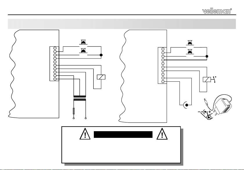
Counting pulses can be applied to the unit in two different ways :
1. + 3V to 12V pulses with respect to ground.
2. Use the + 5V connection for push buttons or relay contacts when there is no power supply from an external source.
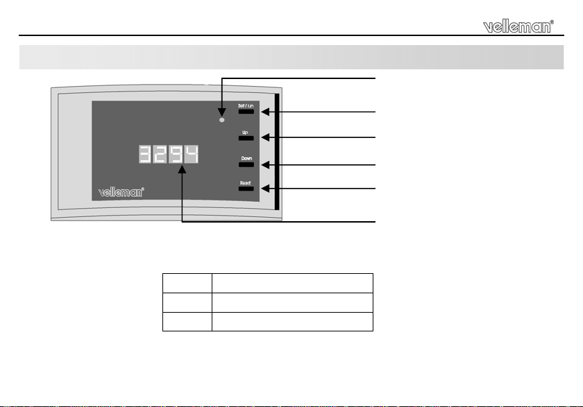
Press “Reset” button briefly to reset the readout. “0000”.
Press the “UP” button to increase the actual value with one.
Press the “DOWN” button to decreases the actual value with one.
Setting the Pre-set value:
It is possible to set a number which will continuously be compared with the content of the counter. If both are equal, then the
output (Equal OUT) is activated.
Press Set/Run (set briefly appears).
Press Up or Down to set the value.
Press Set/Run to store the value (Run appears).
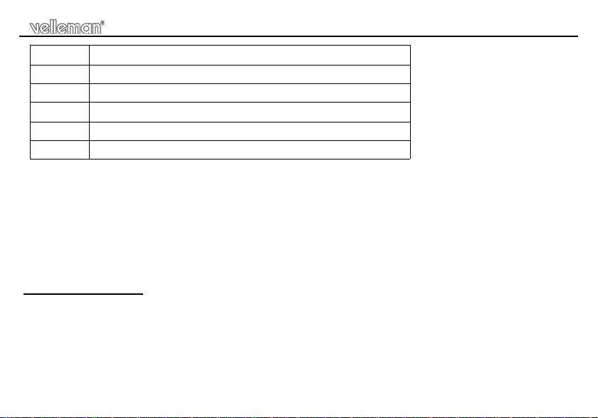
Error code Description
Err. 2 Error in the keyboard section.
Err. 3 The switches are in the wrong position. ’DIP SWITCH’
Err. 4 Input A and B are at the same time active
Err. 5 Input A is active during self-test or input A is possibly malfunctioning.
Err. 6 Input B is active during self-test or input B is possibly malfunctioning.
Operation

8
Operation
Counter settings :
The counter can be used for decade or modulo 60 (clock) counting, an internal oscillator can be provided for use in modulo
60-mode
1. COUNTER SETTINGS
FUNCTION DIP SWITCH
OFF ON
Decade counter 1
Modulo 60 : hh:mm (23.59) 2 1
Modulo 60 : mm:ss. (59.59) 1 & 2
2. DEBOUNCE SETTING
Normal debounce 3
Long debounce 3
External pulses 4
Internal oscillator 4
3. INPUT SETTING
When changing the position of one of the switches, the current counter value and the pre-set value will be erased.

9
Safety and warning instructions
All repairs should be executed by qualified technicians.
Avoid the installation of the module in locations with standing or running water or excessive humidity. Indoor use
only ! SAFETY INSTRUCTIONS
Do not attempt to disassemble the unit as it does notcontain any parts that are to be serviced by the user. (Tampering voids warranty)
Handle the module gently and carefully. Dropping it can damage the circuit board andcase.
Never exceed the protection limit values indicated in the specifications.
As safety requirement vary, please check with your local authorities.
No objects or liquids should be allowed to penetrate the housing.
Make sure that the ventilation slots are not blocked.
Disconnect the module from the ACpower before connecting new devices.
Wipe the device witha dry and clean cloth. Do not use detergents orother liquids that may damage the housing.
Keep the device away fromchildren.
Facilitate the operation of the device by familiarising yourself with its adjustments and indications.
Velleman modules are not suitable for use or as part of life support systems, or systems that might create hazardous situations of kind.
Repair under warranty is only possible with date and proof of purchase.
WARNINGS

10

11
Waarschuwingen en inhoud
Hartelijk dank voor de aanschaf van deze universele teller.
WAARSCHUWING
ZORG ERVOOR DAT DEZE NIET MET DE VOEDING VERBONDEN IS
TIJDENS HET AANSLUITEN.
LEES DE INSTRUCTIES AANDACHTIG ZODAT U HET TOESTEL CORRECT
EN VEILIG KUNT GEBRUIKEN. ZIE PAGINA 17
!
WAARBORG
Dit produkt is gewaarborgd wat betreft gebreken in materialen en vakmanschap op het ogenblik van de aankoop en dit gedurende een periode van EEN JAAR vanaf de
aankoop. De waarborg geldt enkel indien het produkt voorgelegd wordt samen met het origineel aankoop bewijs. De verplichtingen van VELLEMAN N.V. beperken zich tot
het herstellen van defecten of, naar vrije keuze van VELLEMAN N.V., tot het vervangen of herstellen van defecte onderdelen. Kosten en risico’s van transport; het wegnemen
en terugplaatsen van het produkt, evenals om het even welke andere kosten die rechtstreeks of onrechtstreeks verband houden met de herstelling, worden niet door
VELLEMAN N.V. vergoed. VELLEMAN N.V. is niet verantwoordelijk voor schade van gelijk welke aard, veroorzaakt door het falen van een product.
INHOUD :
KENMERKEN & SPECIFICATIES...................................................................................................................................................... 12
SAMENBOUW..................................................................................................................................................................................... 13
BEDIENING......................................................................................................................................................................................... 14
VEILIIGHEIDSAANWIJZINGEN EN WAARSCHUWINGEN............................................................................................................. 17

12
Kenmerken en specificaties
Specificaties & Eigenschappen
SPECIFICATIES*
Ideaal voor het tellen van personen, onderdelen, score, enz...
Optellen of aftellen van tijden.
Telimpulsen d.m.v de drukknoppen op de print of door externe pulsen.
Uitlezing : standaard of tijd (hh:mm en mm:sec.).
Ingebouwde oscillator laat toe tijdmetingen te doen.
Vooraf instelbare waarde met (gelijke) uitgang.
Zelfdiagnose bij het opstarten.
EIGENSCHAPPEN
Ingangsspanning :...................................................................................... 3 - 12V DC (ook voor spanningsloos contact).
"EQUAL" uitgang : ............................................................................................................................... 5VDC / max 50mA.
Max. telsnelheid :............................................................................................200 / sec. (2 / sec. met extra ontdendering)
Max. tellerstand :...........................................................................................................4 digits (9999 / 23h59m / 59m59s)
Voedingsspanning : ..................................................................................................... 9 tot 12VDC of 2 x 9VAC / 300mA.
Stroomverbruik :.............................................................................................................................................max. 150mA.
Afmetingen :...............................................................................................................165 x 90 x 35mm (6,5" x 3.5" x 1,4")
* wijzigingen voorbehouden

13
Samenbouw
Samenbouw
BEHUIZING
PCB
DRUKKNOPPEN
DEKSEL
FRONT PANEEL

14
Bediening
Bediening
‘Pre-set’ drukknop
Omhoogtoets
Omlaagtoets
Resettoets
Teller display
Weergave v/d uitgang ‘Equal ‘
Eq. Out
Als alle verbindingen gemaakt zijn en aangesloten aan de voeding zullen de 4 LED displays oplichten en verschijnt het
nummer ‘107’, daarna verschijnen de volgende boodschappen :
Indien tijdens de zelftest een fout werd gevonden, zal er een foutcode verschijnen. Verschijnt de boodschap “GOOD” dan is
de module gebruiksklaar.
r x. x x Versienummer
T E S T Uitvoering van zelftest
G O O D Intern gedeelte is correct

15
De fouten “Err5” en “Err6”
verschijnen als tijdens de
zelftest tel impulsen ontvangen
werden, d.m.v. de ‘reset’ toets
kort in te drukken kan ieder
foutmelding omzeild worden.
De ingang kan men op twee manieren voorzien van impulsen :
1. +3V tot 12V spanningspulsen t.o.v. de massa.
2. Gebruik de +5V uitgangaansluiting voor drukknoppen of relaiscontacten wanneer er geen spanning is van een externe
bron. Druk kort op de ‘Reset’ drukknop om de tellerstand te resetten(0000).
“UP” kort indrukken verhoogt de tellerstand met één.
“Down” kort indrukken verlaagt de tellerstand met één.
Instellen van het “Pre-set” geheugen:
Men kan een waarde ingeven die daarna continu wordt vergeleken met de huidige tellerstand. De “E.OUT” wordt geactiveerd
indien beide identiek zijn.
Druk op de toets Set/Run (Set verschijnt eventjes).
De waarde kan worden aangepast d.m.v. de Up of Down toetsen.
Druk op de toets Set/run voor het opslaan v/d waarde (Run verschijnt eventjes).
Foutcode Omschrijving
Err. 2 Fout in het toetsenbordgedeelte.
Err. 3 De schakelaars staan in de verkeerde stand (Dip Switch).
Err. 4 Ingang A & B zijn samen actief.
Err. 5 Ingang A is actief tijdens de zelftest of is mogelijk beschadigt.
Err. 6 Ingang B is actief tijdens de zelftest of is mogelijk beschadigt.
Bediening

16
Bediening
Teller instelling :
De tellermodule kan worden gebruikt als 10-delige teller, een intern oscillator kan worden gebruikt als men het 60-delig
stelsel kiest.
1. TELLER INSTELLING
FUNCTIE DIP SWITCH
OFF ON
10-delig stelsel 1
60-delig hh:mm (23:59) 2 1
60-delig mm:ss. (59.59) 1 & 2
2. ONTSTORINGS INSTELLING
Normale ontstoring 3
Extra onstoring 3
Externe impulsen 4
Interne Impulsgenerator (oscillator) 4
3. INGANG INSTELLINGEN
Bij het wijzigen van de stand van één van de schakelaars, zal zowel de huidige als de ‘Pre-set’
tellerwaarde gewist worden.

17
Veiligheidsaanwijzingen en waarschuwingen
Reparaties mogen uitsluitend uitgevoerd worden door vakkundige personen.
Installeer de module niet op plaatsen met staand of stromend water of in ruimtes met een te hoge vochtigheids-
graad. Binnengebruik enkel! VEILIGHEIDSAANWIJZINGEN
Probeer het apparaat niet te demonteren : Door modifiëring vervalt de garantie.
Vermijd een ruwe behandeling. Stoten of laten vallen kunnen ernstige schade aanbrengen.
Overschrijdt nooit de opgegeven veiligheidswaarden in de specificaties.
Vermits de veiligheid vereisten verschillen van plaats tot plaats, zorg daarom dat Uw montage voldoet aan de plaatselijke gel-
dende vereisten.
Let op dat er geen voorwerpen of vloeistoffen in het toestel dringen.
Zorg ervoor dat de lucht ongehinderd door de ventilatiegleuven van het toestel kan stromen.
Zorg ervoor dat de netspanning altijd uitgeschakeld is bij het aansluiten van nieuwe toestellen.
Reinig het toestel met een droge doek. Vermijd gebruik van reinigingsmiddelen daar deze de behuizing kunnen beschadigen.
Houdt vooral kinderen uit de buurt van het toestel dit ter veiligheid van hun zelf.
Zorgt ervoor dat u met alle bedieningselementen vertrouwd raakt, wanneer U met het toestel zal werken.
Velleman modules zijn niet geschikt voor gebruik in of als gedeelte van systemen welke levensfuncties in stand houden of syste-
men welke gevaarlijke situaties van gelijk welke aard kunnen veroorzaken.
Herstelling onder garantie is enkel mogelijk met aankoopbewijs.
WAARSCHUWINGEN

18

19
Avertissements et sommaire
Nous vous félicitons pour l’achat de ce compteur avance.
AVERTISSEMENTS
VEILLEZ A CE QUE LE MODULE NE SOIT PAS CONNECTE AU
RESEAU PENDANT RACCORDEMENT.
LIRE ATTENTIVEMENT LES INSTRUCTIONS DE SERVICE ET DE MAINTE-
NANCE DU PRESENT MANUEL. VOIR PAGE 25
!
GARANTIE
Ce produit est garanti contre les défauts des composantes et de fabrication au moment de l’achat, et ce pour une période d’UN AN à partir de la date d’achat. Cette garantie
est uniquement valable si le produit est accompagné de la preuve d’achat originale. Les obligations de VELLEMAN S.A. se limitent à la réparation des défauts ou, sur seule
décision de VELLEMAN S.A., au remplacement ou à la réparation des pièces défectueuses. Les frais et les risques de transport, l’enlèvement et le renvoi du produit, ainsi que
tous autres frais liés directement ou indirectement à la réparation, ne sont pas pris en charge par VELLEMAN S.A. VELLEMAN S.A. n’est pas responsable des dégâts, quels
qu’ils soient, provoqués par le mauvais fonctionnement d’un produit.
SOMMAIRE :
CARACTERISTIQUES & DONNEES TECHNIQUES........................................................................................................................ 20
ASSEMBLAGE.................................................................................................................................................................................... 21
COMMANDE ....................................................................................................................................................................................... 22
CONSIGNES DE SECURITE ET MISES EN GARDE....................................................................................................................... 25

20
Caractéristiques et données techniques
DONNEES TECHNIQUES*
Très pratique lorsqu'il faut compter, marquer les points dans un match sportif, etc...
Comptage d'impulsions (up/down).
Comptage d'impulsions via des boutons-poussoirs incorporés ou externes.
Modes d'affichage : normal ou temps (hh:mm:ss).
L'oscillateur interne permet de mesurer des unités de temps.
Comparaison entre la valeur mesurée et la valeur préinstaurée.
Auto-diagnostique lors de l'activation.
CARACTERISTIQUES
Tension d'entrée : ............................................................................... 3-12V DC (convient pour un contact sans tension)
Sortie égale :........................................................................................................................................ 5VDC / max. 50mA
Vitesse de comptage max. :..........................................................................200Hz. (2Hz élimination du rebondissement)
Comptage max. :...........................................................................................................4 digits (9999 / 23h59m / 59m59s)
Alimentation :.................................................................................................................................9 -12VDC ou 2 x 9VAC
Consommation :..............................................................................................................................................150mA max.
Dimensions :..............................................................................................................165 x 90 x 35mm (6,5" x 3.5" x 1,4")
*Sous réserve de modifications.
Table of contents
Languages:
Other Velleman Modules Cash Counter manuals