Velleman Velleman-Kit K6400 User manual

Total solder points: 187
Difficulty level:
beginner 1o2þ3o4o5oadvanced
K6400
Code Lock
ILLUSTRATED ASSEMBLY MANUAL H6400IP-2
Features
þMore than 3000 codes possible.
þState indication by LED.
þPulse or switch output.
þNine digits of which 4 code digits.
þSecured against polarity reversal.
specifications :
•Power supply : 9 to 15VDC or 8 to 12VAC.
•Relay output : 5A / 220V.
•Time limit for code determination : +/-5sec.
•Current consumption : Output OFF: 0,3µA
Output ON : 40mA
VELLEMAN Components NV
Legen Heirweg 33
9890 Gavere
Belgium
http://www.velleman.be
http://www.velleman-kit.com
3
1. Assembly (Skipping this can lead to troubles ! )
Ok, so we have your attention. These hints will help you to make this project success-
ful. Read them carefully.
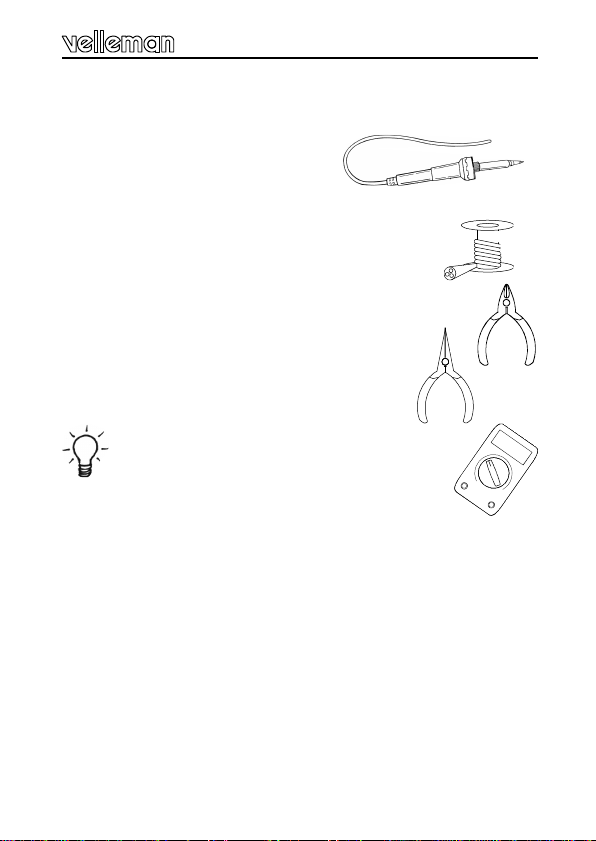
1.1 Make sure you have the right tools:
•A good quality soldering iron (25-40W) with a
small tip.
•Wipe it often on a wet sponge or cloth, to keep it clean; then apply solder to the
tip, to give it a wet look. This is called ‘thinning’ and will protect
the tip, and enables you to make good connections. When solder
rolls off the tip, it needs cleaning.
•Thin raisin-core solder. Do not use any flux or grease.
•A diagonal cutter to trim excess wires. To avoid injury when cutting
excess leads, hold the lead so they cannot fly towards the
eyes.
•Needle nose pliers, for bending leads, or to hold components
in place.
•Small blade and phillips screwdrivers. A basic range is f
fine.
For some projects, a basic multi-meter is required, or might
be handy
1.2 Assembly Hints :
⇒Make sure the skill level matches your experience, to avoid disappointments.
⇒Follow the instructions carefully. Read and understand the entire step before you
perform each operation.
⇒Perform the assembly in the correct order as stated in this manual
⇒Position all parts on the PCB (Printed Circuit Board) as shown on the drawings.
⇒Values on the circuit diagram are subject to changes.
⇒Values in this assembly guide are correct*
⇒Use the check-boxes to mark your progress.
⇒Please read the included information on safety and customer service
* Typographical inaccuracies excluded. Always look for possible last minute manual
updates, indicated as ‘NOTE’ on a separate leaflet.
0.000
Assembly hints
4
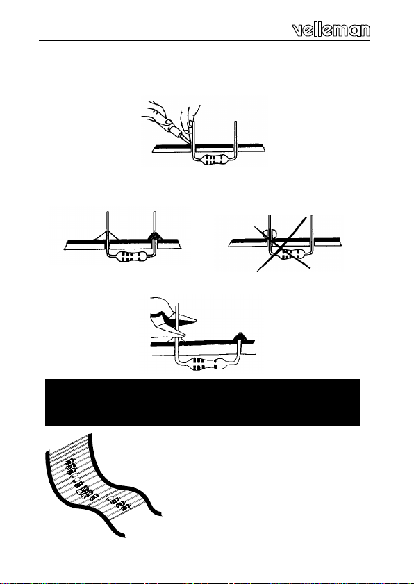
1.3 Soldering Hints :
Mount the component against the PCB surface and carefully solder the
leads
Make sure the solder joints are cone-shaped and shiny
Trim excess leads as close as possible to the solder joint
REMOVE THEM FROM THE TAPE
ONE AT A TIME !
AXIAL COMPONENTS ARE TAPED IN THE CORRECT
MOUNTING SEQUENCE !
Assembly hints
IPESF SDK NDGB FNL
C
O
D
E
CODICE
COLORE CODIGO
DE CORES CODIGO
DE COL-
ORES
VÄRI
KOODI FÄRG
SCHEMA FARVE-
KODE FARGE-
KODE FARB
KODE COLOUR
CODE CODIFI-
CATION
DES COU-
LEURS
KLEUR
KODE C
O
D
E
0Nero Preto Negro Musta Svart Sort Sort Schwarz Black Noir Zwart 0
1Marrone Castanho Marrón Ruskea Brun Brun Brun Braun Brown Brun Bruin 1
2Rosso Encarnado Rojo Punainen Röd Rød Rød Rot Red Rouge Rood 2
3Aranciato Laranja Naranjado Oranssi Orange Orange Orange Orange Orange Orange Oranje 3
4Giallo Amarelo Amarillo Keltainen Gul Gul Gul Gelb Yellow Jaune Geel 4
5Verde Verde Verde Vihreä Grön Grøn Grønn Grün Green Vert Groen 5
6Blu Azul Azul Sininen Blå Blå Blå Blau Blue Bleu Blauw 6
7Viola Violeta Morado Purppura Lila Violet Violet Violet Purple Violet Paars 7
8Grigio Cinzento Gris Harmaa Grå Grå Grå Grau Grey Gris Grijs 8
9Bianco Branco Blanco Valkoinen Vit Hvid Hvidt Weiss White Blanc Wit 9
AArgento Prateado Plata Hopea Silver Sølv Sølv Silber Silver Argent Zilver A
BOro Dourado Oro Kulta Guld Guld Guldl Gold Gold Or Goud B
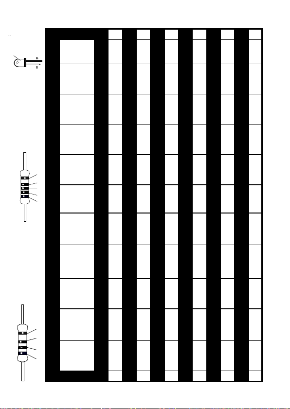
5%
4K7= ( 4 - 7 - 2 - B )
1%
4K7= ( 4 - 7 - 0 - 1 - 1 )
COLOR= 2… 5
COLOR= 2...5

6
Construction
This code lock can be used to switch an alarm (e.g. car alarm
K3504) on and off as well as to open a door lock. A LED on the
operation panel reflects the state of the "lock". You can easily
determine the code yourself. Thanks to its reduced dimensions,
this code lock is very well suited to be built into a standard hous-
ing. Its fully closed operation panel allows it to be used inside as
well as outside.
qSW1...SW9
1. Push buttons
SW...
qLD1
2. Leds
Watch the polarity !
COLOR= 2...5
LD...
CATHODE
The unit consist out of two PCB’s, one is the keyboard
module “P6400S” and the other is the master module “P6400B”.
First we will start with the Keyboard module, then we assemble
the master module.
FTIP : The picture on the packaging can be used as a
guideline. However, due to possible changes it is not 100%
reliable.
Construction of P6400S
7
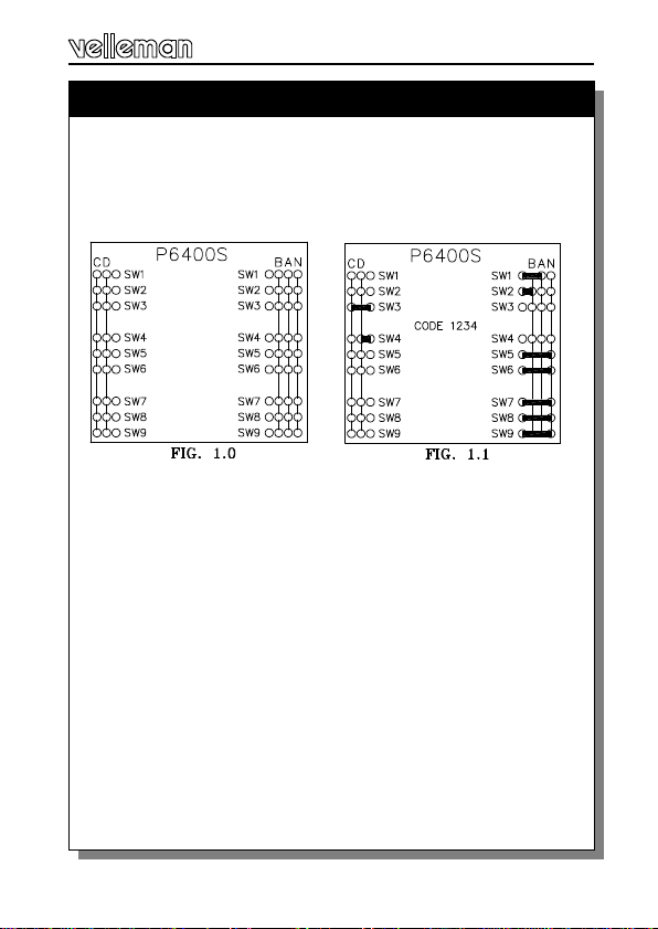
The code
The four code digits are determined by fitting wire
jumpers, see figure 1.0.
Drawing 1.1 shows the connections for code 1234 as an
example.
FAttention : the wire jumpers that build the code must
be as close to the pcb as possible, because other-
wise they will touch the aluminium front panel!
The code sequence is determined by connecting the lines
A, respectively B, C and D to the connecting terminals
(keys 1 through 9) at the inside of the pcb, where line A is
the first code, B the second code and so on. The unused
keys (normally 5) are connected to line N.
Determining the code
8
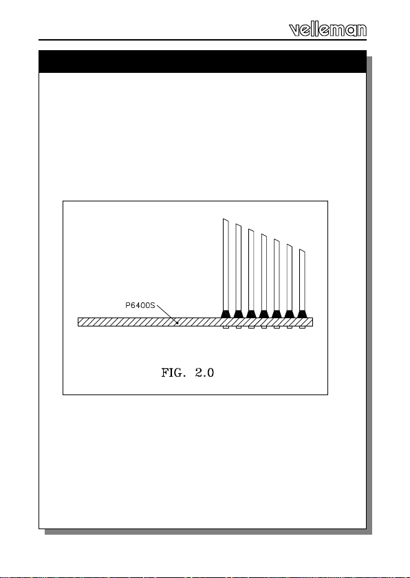
Preparation
Fit seven non insulated wires at the solder side of the pcb.
These wires will be used later on for through connection
to the master module (see fig. 2.0).
FAttention : the wires at the component side must be
cut off as close to the pcb as possible.
Preparation

9
Construction
Construction of P6400B
qJ
on/off function of the key lock.
qJ1
Fit wire jumper J1 in case you intend to use the on/off
function of the key lock.
If you don't fit this wire jumper, then, at the input of the
code, the code lock will only generate a pulse (in general
this mode is used with door locks).
"closed" contact or "open" contact .
qNC or NO
Fit wire jumper NC if you intend to use the normally
"closed" contact of the relay, or wire jumper NO if you
intend to use the normally "open" contact of the relay.
FATTENTION : after the relay has been fitted, these
wire jumpers are no longer accessible.
1. Jumpers

10
qR8 : 10 (1-0-0-B)
qR9 : 220 (2-2-1-B)
qR11 : 1K5 (1-5-2-B)
2. Resistors.
R...
qIC1: 14p
4. IC socket, Watch the
position of the notch !
qT1, T2 : BC547B or eq
5. Transistors.
qC1 : 10µF
qC2 : 470µF
7. Electrolytic
Capacitors. Watch the
polarity !
C...
Construction
qD1 : 1N4148 or eq.
qD5 : 1N4000
qD2...D4 : 1N4148 or eq
FThe side with the mark
comes in the smallest hole
marked C !
D...
CATHODE
3. Diodes
D
qR1: 470K (4-7-4-B)
qR2...R4 : 47K (4-7-3-B)
qR5...R7 : 10K (1-1-3-B)
6. Resistors.
R...

11
qIC1: CD4066
10. IC, Check the
position of the notch !
Construction
qJ2 : 2 x 2p
8. Screw connector
qRY1 : VR15M121C
9. Relay
12
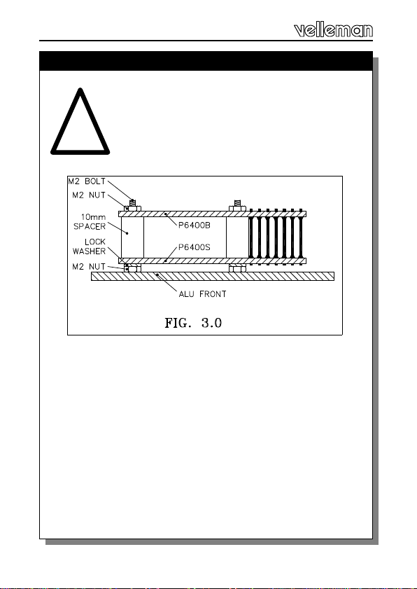
CHECK THE WHOLE MOUNTING ONCE
MORE THOROUGHLY AND DON'T FOR-
GET THE CODE, BECAUSE AFTER THE
FOLLOWING ASSEMBLY IT WON'T BE
ACCESSIBLE ANY MORE.
Pass two 2mm bolts through the front panel and fix them
using a nut. Then pass a lock washer over the bolts fol-
lowed by the keyboard module. Take care that the LED is
in the front panel. Normally, neither the LED nor the push
buttons may pass through the front panel. The push but-
tons must be flush with the front side.
Pass a 10mm distance tube over the two bolts, followed
by the master module. Also take care that the through
connections pass through the master module.
Now fix both modules using two nuts, where after you can
solder the through connections (pay attention to short-
circuits).
Assembly (fig 3.0)
Assembly
!
13
Connect a 9 to 15VDC or a 8 to 12VAC to the points V
and GND. (V is the plus pole in the case of direct current).
Put the front panel film next to the keyboard and enter the
right code (in the case of a pulse output this has to be
done within 5 seconds). If everything is going on well, now
the relay should close and open again in case pulse out-
put mode has been ¬selected. If however you have cho-
sen for a constant switch position, then you can cause the
relay to open by entering a ¬digit NOT belonging to the
code digits.
GTip: should the opening time of the relay (in the case
of the pulse output mode) be too short, fit a 22µF ca-
pacitor instead of C1 to change that time.
Test and Usage
Test & building in
In case you use the key lock outside, it is advisable to
mount it sunk, so that no water can soak in. For safety
you better first fix the code lock into the wall where after
you stick the film to it, so that the fixation screws are hid-
den "behind" the film.
Take care that, when sticking the film, the "LED WIN-
DOW" corresponds with the hole in the aluminium.
Building in
14
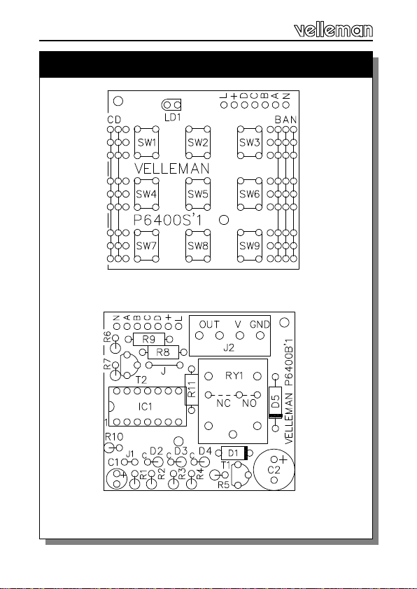
P6400S -Keyboard
P6400B -master
PCB layout
PCB
15
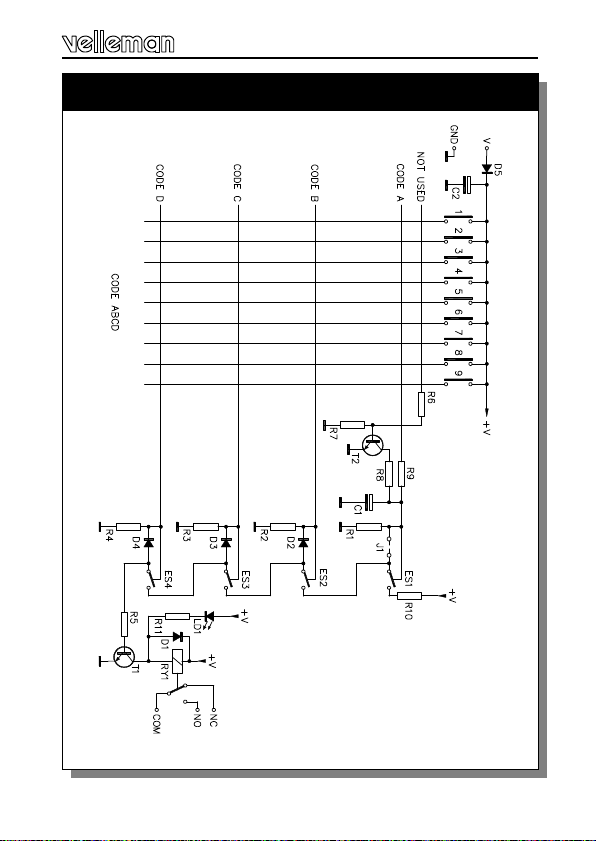
Schematic diagram.
Diagram

VELLEMAN Components NV
Legen Heirweg 33
9890 Gavere
Belgium Europe
http://www.velleman.be
http://www.velleman-kit.com
Modifications and typographical errors reserved
© Velleman Components nv.
H6400IP -2001 -ED2
Other Velleman Lock manuals


