Hongda USA DL210 User manual

Table of Contents
1. Product and Accessories …………………………………………………..2
1.1 Parts List……………………………………………………………….2
1.2 Parts Identification…………………………………………………......3
2. Installation………………………………………………………………….5
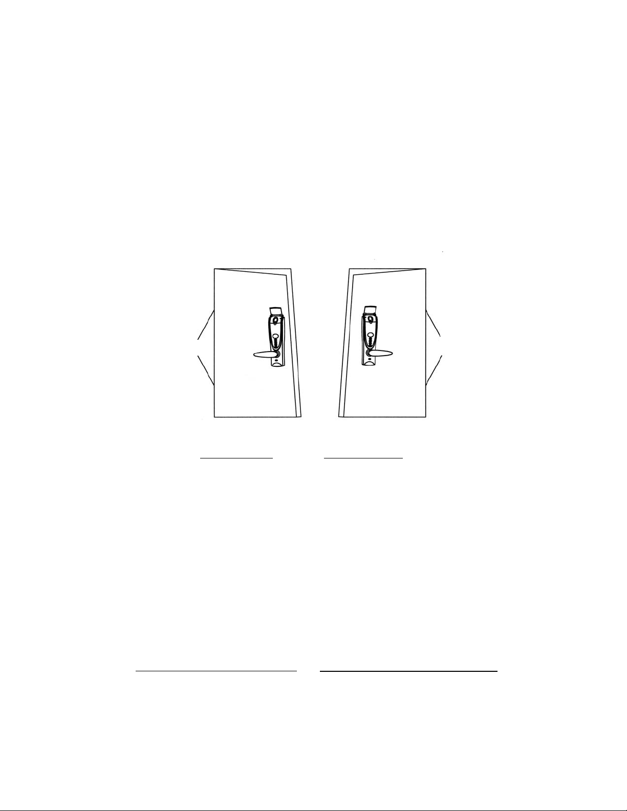
2.1 Preparation before Installation…………………………………………5
2.2 Drill Holes……………………………………………………………...6
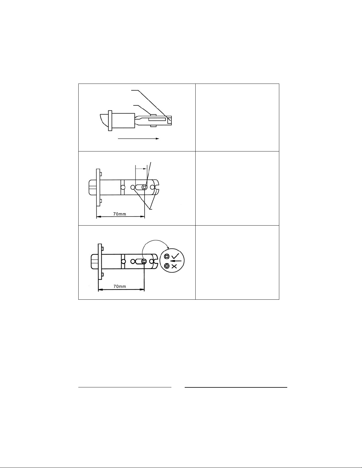
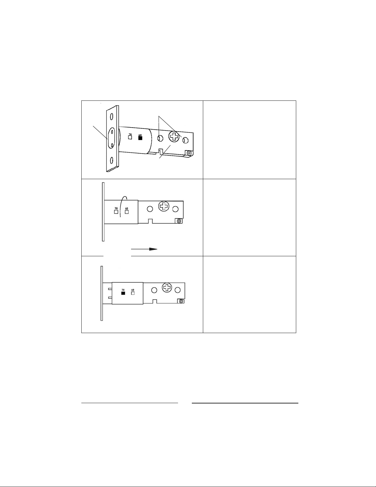
2.3 Adjust Latch’s Backset………………………………………………....6
2.4 Adjust Deadbolt’s Backset……………………………………………...7
3 Install Latch, Deadbolt and Strikes ………………………………………...9
3.1 Install Latch and Deadbolt ……………………………………………..9
3.2 Install Strikes and Lining Boxes………………………………………10
4 Install the Lock Units………………………………………………………11
4.1 Adjust Torque Bar Length…………………………………………......11
4.2 Remove Plate and Screws from Inside Section ……………………....11
4.3 Mounting of Outside Section onto door……………………………....12
4.4 Mounting the Plat to Fix Outside Section onto Door ………………...13
4.5 Install Inside Section of Lock ………………………………………...14
4.6 Check and Adjust after Installation …………………………………..15
5Problems or Feedback …………………………………………………….16
Shepherd 210A Installation Manual V1.1 ©©Copyright 2004. Hongda USA Inc.
2

1. Product and Accessories
1.1 Parts List
After opening the package, please check the product and accessories. If any are
missing or damaged, please contact your dealer for replacement.
Inside unit Outside unit Pinch screws
Deadbolt Deadbolt strike Deadbolt strike lining box
Latch Latch strike Latch strike lining box
Square axis for latch Wood screw Emergency keys
Shepherd 210A Installation Manual V1.1 ©©Copyright 2004. Hongda USA Inc.
3

1.2 Parts Identification
1. Decoration plate 14. LED display
2. Sliding dust cover 15. Inside unlocking button
3. Green LED indicator 16. Inside locking button
Shepherd 210A Installation Manual V1.1 ©©Copyright 2004. Hongda USA Inc.
4

4. Red LED indicator 17. Battery compartment knob
5. Fingerprint scanning window 18. Battery compartment
6. Power on switch 19. Pinch screw holes
7. Outside locking button 20. Inside lever
8. Emergency keyhole cover 21. Inside unit body
9. Outside unit body 22. Deadbolt keyhole
10. Deadbolt 23. Latch emergency keyhole
11.Latch 24. Deadbolt emergency release hole
12.Outside lever 25. Pinch screw hole
13.Function keys
Shepherd 210A Installation Manual V1.1 ©©Copyright 2004. Hongda USA Inc.
5

2. Installation
2.1 Preparation before Installation
Your lock must correspond to your door being left-handed or right-handed. If
not, you should ask your seller to exchange it. (Refer to Figure1)
Hinge
Hinge
Left-Hand Door Right-Hand Door
Fig 1: Viewing from the outside; definition of doors
ƁTip: How to determine the door opening direction?
Standing outdoor and face the door: If the hinge is at the left side of the
door, the door is a left-handed door - the left-handed lock should be used. If
the hinge is at the right side of the door, the door is a right-handed door -
the right-handed lock should be used.
The lock lever is designed to be interchangeable with the popular Schlage or
Kwikset standard for 2 lock hole doors. If your door has only one hole or no
holes in the door, follow the instructions below. (Note: Most hardware stores
have 2-1/8” and 1” hole cutters that fit standard hand drills.)
Shepherd 210A Installation Manual V1.1 ©©Copyright 2004. Hongda USA Inc.
6

2.2 Drill Holes
(1) Paste the provided cutout template on the door as shown in the figure. Mark
1” holes at center of door edge and make 2” holes at the surface of the door (the
offset is 2 3/8” or 2 3/4” from door edge to the center of the 2” hole).
(2) Drill two 1” holes on door edge. And drill two 2” holes on the door surface.
Hint: To avoid cracking the door surface, the 2” holes should be drilled from
both sides.
(3) There are adjustable backsets for the latch and deadbolt. Set them to either 2
3/8” or 2 3/4” as appropriate for your door.
2.3 Adjust Latch’s Backset
The backset is at the 2 3/8”
position, when the product
is shipped from the factory.
The left of adjustment hole Regulato
r
pin
Screw-post hole
Shepherd 210A Installation Manual V1.1 ©©Copyright 2004. Hongda USA Inc.
7

Pull regulator pin to the right
edge.
The backset has been
adjusted to 2 3/4” position.
Make sure the regulator
pin is at the correct angle
as shown.
The clip of regulator pin
Regulato
r
pin
Pull
The right edge of adjust hole
Screw-
p
ost hole
Shepherd 210A Installation Manual V1.1 ©©Copyright 2004. Hongda USA Inc.
8

2.4 Adjust the Deadbolt’s Backset
The backset is at the 2 3/8” (60
mm) position, when the product
is shipped from the factory.
Insert a flat screwdriver into
driving board hole, turn driving
board to let the deadbolt head
draws in.
Pull regulator pin up, firmly
hold driving board and driving
spring and pull right until the 2
3/4” screw hole coincides with
driving board hole.
Figure shows the backset is in
2 3/4” (70 mm) position.
Pinch Screw
Holes
Deadbolt
Head
Driving
Board Hole
Turn
Pull
Shepherd 210A Installation Manual V1.1 ©©Copyright 2004. Hongda USA Inc.
9

3 Install Latch, Deadbolt and Strikes
3.1 Install Latch and Deadbolt
Insert the lock bolt into the hole,
mark the frame lines of foil board.
The frame lines should be parallel
with the door edge.
Dig a support notch 1/8” in depth.
The notch edge lines should be
parallel with the door edge.
Insert latch and deadbolt, and tighten
the screws (the slanted plane of latch
should face the door closing
direction, and the UP mark of the
deadbolt should point up).
After the screws are tightened, the
foil board should be exactly in the
door center and parallel with door
edge.
Shepherd 210A Installation Manual V1.1 ©©Copyright 2004. Hongda USA Inc.
10

3.2 Install Strikes and Lining Boxes
Close the door; use pencil to mark
strike hole in the doorjamb from face
hole.
Cut out a square cavity to accept
the strike box at the marked
location in the doorjamb.
Draw strike plate line and screw
holes Cut 1/16” notches for the strike
plates.
Install strikes, tighten the screws.
Shepherd 210A Installation Manual V1.1 ©©Copyright 2004. Hongda USA Inc.
11

4 Install the Lock Units
(Note: The DL210A fits standard door thicknesses of 1 1/2” to 2 1/8”. It is
possible to fit doors down to 1” and up to 2 1/4” in thickness door by ordering
special length of torque bars and square axes from manufactory.
4.1 Adjust Torque Bar Length
The length of torque bar is longer than normal when shipped from the factory. You
need to cut off the length of torque bar equal to thickness of the door. You can put
the outside section on the table, and let deadbolt toward up, measure the length of
deadbolt (from the base of outside section) and make a mark at thickness of the door,
than cut it.
Fig 2 Fig 3
Torque
Bar
Set Torque
bar position
horizontally Dead
Bolt
Square
A
xel Latch
Outside
Unit Outside
Unit
Inner Doo
r
Surface Cable
Doo
r
Outer Door
Surface
4.2 Remove Plate and Screws from Inside Section
Remove the battery cover on Inside Section of lock. And remove Plate from
Shepherd 210A Installation Manual V1.1 ©©Copyright 2004. Hongda USA Inc.
12

Inside Section by unscrewing the two Ascrews on the side of the lock. Save
removed parts for later use. (Fig 4, 5)
Shepherd 210A Installation Manual V1.1 ©©Copyright 2004. Hongda USA Inc.
13
Screw A
AScrews
Plate
Fig 4 Fig 5
4.3 Mounting of Outside Section onto door
1. Put rubber gasket on the Outside Section of lock, with the smooth side
away from lock. (Ignore shape of cutout holes; it doesn’t matter.) (Fig 6, 7)
Fig 6 Fig 7

2. Be sure you start from the outside of the door with the Outside Section
of the lock and feed cable to the inside through the second hole from the
bottom.
3. EXTEND the deadbolt. Start feeding the two bolts near the bottom of
the lock through the two respective holes in the door. When started,
start jiggling the lock into the door while positioning the loose torque
bar at the deadbolt end of the lock so it slips HORIZONTALLY into
the deadbolt gear screw.
4. Work the unit until it is flush against the door with the rubber gasket
aligned perfectly around the lock, then hold in place so it doesn’t slip
out.
Shepherd 210A Installation Manual V1.1 ©©Copyright 2004. Hongda USA Inc.
14
Fig 8 Fig 9
4.4 Mounting the Plat to Fix Outside Section onto Door
Position the Plate taken off earlier from the Inside Section (Fig. 5) on the inside
of the door with the two tabs at the top and sticking out. Use two Bscrews
(slightly shorter of the four long pinch screws supplied) for mounting through
the two holes near the top of the lock. Screw in tightly making sure rubber
gasket is positioned evenly around lock.

Shepherd 210A Installation Manual V1.1 ©©Copyright 2004. Hongda USA Inc.
15
BScrews
Cable
Put Spring
Square
A
xel
Fig 10 Fig 11
4.5 Install Inside Section of Lock
1. Plug in the Cable (Fig. 11) to the one connector available on the circuit
board.
2. Put the little Spring into the square axel hole on the inside of the
Outside Section, then insert the square axel into the hole, pushing
against the spring.
3. Turn deadbolt finger knob until the slot lings up with the torque bar and
push into place.
4. Work the Inside Section into place. Make sure the cable doesn’t block
the way for CScrews.
5. Fasten Inside Section in place by replacing the two small AScrews on
the side of the unit. (Fig. 12)
6. Fasten the two long CScrews on the lower portion of the unit. (Fig. 13)
Note: Don’t fasten screws too tight before final checkup.

Shepherd 210A Installation Manual V1.1 ©©Copyright 2004. Hongda USA Inc.
16
AScrew
CScrews
Fig 12 Fig 13
4.6 Check and Adjust after Installation
Check the mechanical assembly as follows:
1. Leave door open, install six (6) AA batteries.
2. Turn inside lever, latch should move freely in and out. Turn outside
lever, latch should not move.
3. Press Inside LOCK button, deadbolt should pop out; press Inside
UNLOCK button, deadbolt should retract.
4. Press Outside LOCK button, deadbolt should pop out.
5. If everything works fine, fasten four screws (screws Aand C) tightly to
finish the installation.
Congratulations! You are done with the installation!
ƁTip: If the deadbolt does not moves smoothly, loosen pinch screws a little
and adjust the lock body position until the deadbolt moves smoothly.
Other manuals for DL210
1
Table of contents
Other Hongda USA Lock manuals
Popular Lock manuals by other brands

COMPX
COMPX Timberline CB-265 instruction sheet

Swann
Swann LockAlarm SW351-LAX operating instructions

Alarm Lock
Alarm Lock Trilogy DL1300 Programming instructions

BASETech
BASETech 1620628 operating instructions

Assa Abloy
Assa Abloy Lockwood 3P82TSS-A11E Mounting instructions

Yale
Yale Brighton Assembly instructions