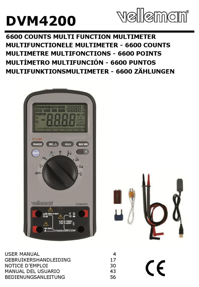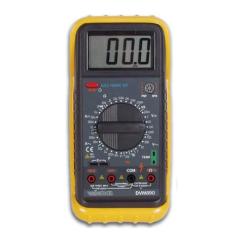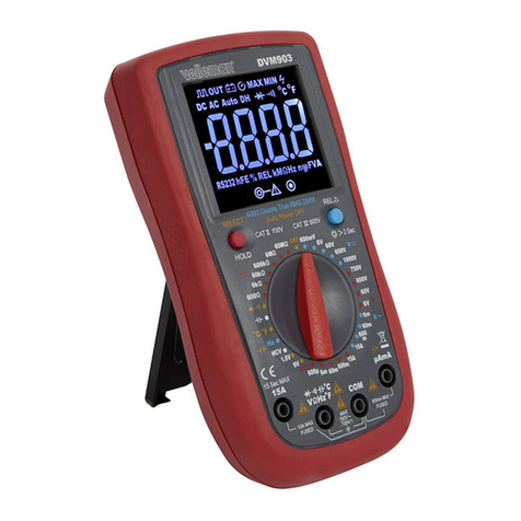
DVM1500 VELLEMAN
4
ON/OFF Switch the meter on or off using this key.
FUNC. Selection of the DC (default) or AC modes, and the (default) or modes. This key function is only
available in the A and ( ) ranges.
RANGE Selection of the automatic (default) or manual modes, selection of manual or auto-ranging modes, selection of
ranges in manual mode. This key function is only available in the V and Ωranges.
HOLD Fixes the current value onto the display. Press again to return to normal mode.
REL Selection of the relative measurement mode. This key function is only available in the V, A, Ω, °C and CAP
ranges.
Switch the backlight on or off using this key. This key function is not available in the EF- range.
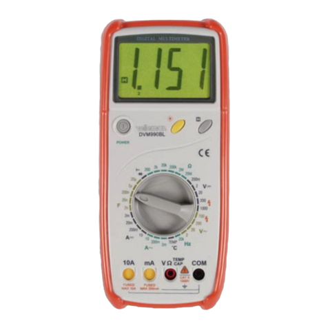
Rotary Switch Use the rotary switch to select the function and the desired ranges.
Terminals
VΩ°CHz: Terminal receiving the red test lead for voltage, resistance, capacitance, diode test,
temperature and frequency measurements.
COM: Terminal receiving the black test lead as common reference.
µAmA: Terminal receiving the red test lead for µA and mA measurements.
10A: Terminal receiving the red test lead for 10A measurements.
4. Operating Instructions
•No-Contact AC Voltage Detector
oSet the rotary switch to the EF- range. The green LED will switch on.
oPlace the top of the multimeter as close as possible to the lead or the mains socket. The green LED will turn red and the
multimeter will beep with the presence of an AC electrical voltage.
•Voltage Measurements
oSet the rotary switch to the V(VAC or VDC) range.
oPress the RANGE button to select your range.
oConnect the black and the red test leads to the COM and the V terminals respectively.
oConnect the test leads to the circuit being measured.
oRead the displayed value. The polarity of the red test lead connection will be indicated when making a DC measurement.
•Resistance Measurements
oSet the rotary switch to the Ωrange.
oConnect the black and red test leads to the COM and Ωterminals respectively.
oConnect the test leads to the circuit being measured and read the displayed value.
oIn order to ensure the best accuracy in measurement of low resistance, short the test leads before measurement. Keep the
test probe resistance in mind and subtract this resistance value from the final measured value.
NOTE:
oFor measuring resistance above 1MΩ, the multimeter may need a few seconds to stabilize the reading. This is normal for
high resistance measuring.
oWhen the input is not connected, i.e. at open circuit, “OL” will be displayed for the overrange condition.
•Continuity Measurements
The auto
owe
-off and backli
ht functions are not available in this measurement function.
To avoid electrical shock and/or damage to the instrument, do not attempt to measure voltages
exceeding 1,000VDC / 750VAC RMS.
To avoid electrical shock and/or damage to the instrument, do not apply more 1,000VDC or 750VAC
RMS between the COM terminal and the earth ground.
To avoid electrical shock and/or damage to the instrument, disconnect the circuit power and discharge
all high-voltage capacitors before measuring resistance.
To avoid electrical shock and/or damage to the instrument, disconnect the circuit power and discharge
all high-voltage capacitors before measuring continuity.
