VEMA PCN101ZP User manual

Programmable welding controller PCN101ZP
VEMA
POWER CONTROLLER
PCN 101 ZP
K1 RUN
Bulgaria, Pleven 5803, 16 Nikolay Haytov str.
tel.: +359 64 870170, +359 888 646100
e-mail: [email protected] https://vema-bg.com
Industrial electronic systems
OPERATION MANUAL

2
The controller can work in a direct mode of continuous welding while user
can correct the welding current by the arrow keys.
In working state with digital input off, the display will read ‘---, meaning that
the controller is ready to start a welding. In settings state the user can set by the
arrow keys the output power (0-100) of the welding current or different
parameters.
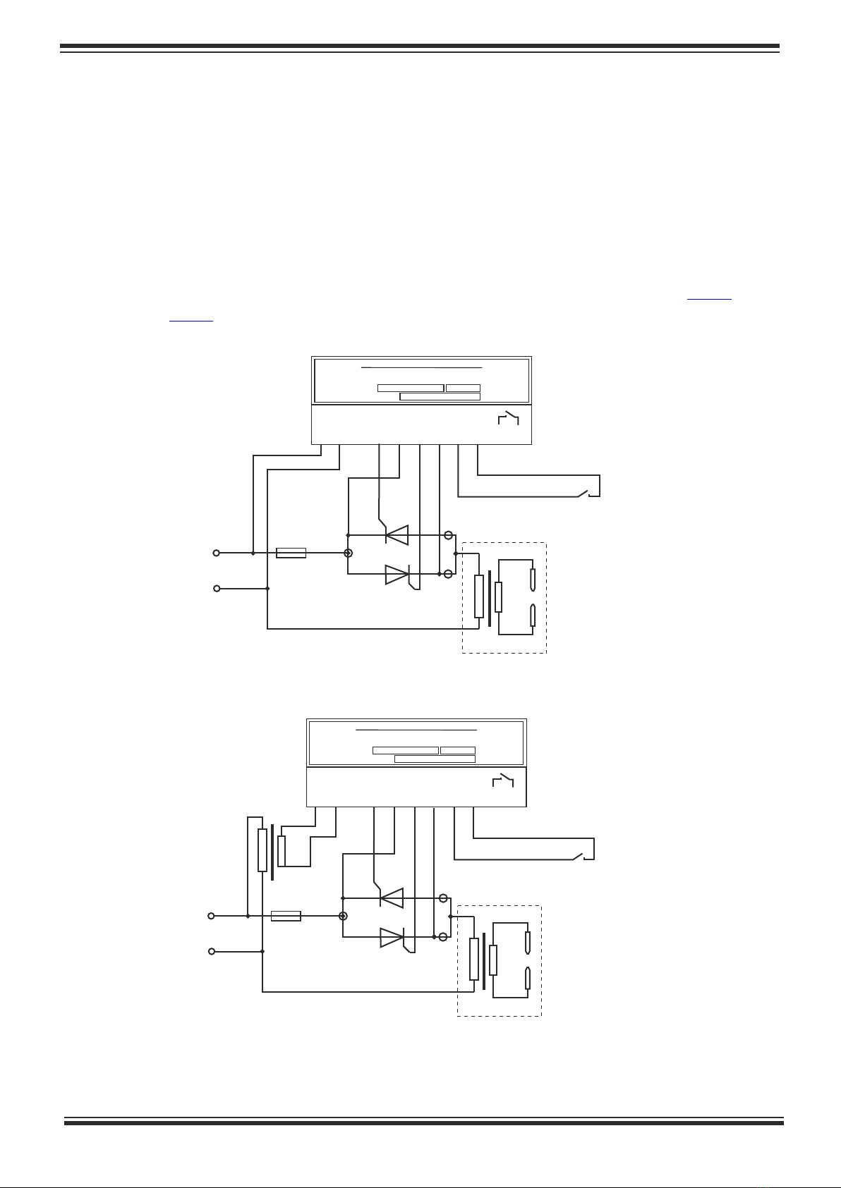
PCN101ZP power controller is used to regulate the phase angle of AC
loads, such as spot welding machines, both single or two-phase. When used with
two-phase loads ( ), a phase matching transformer 400/230V is needed, Fig.6
unless it is not provided in the controlled device. Without such a transformer as a
power supply to PCN101ZP, there will be a 30 degrees phase shift between
controller and loads, thus real control will not be possible.
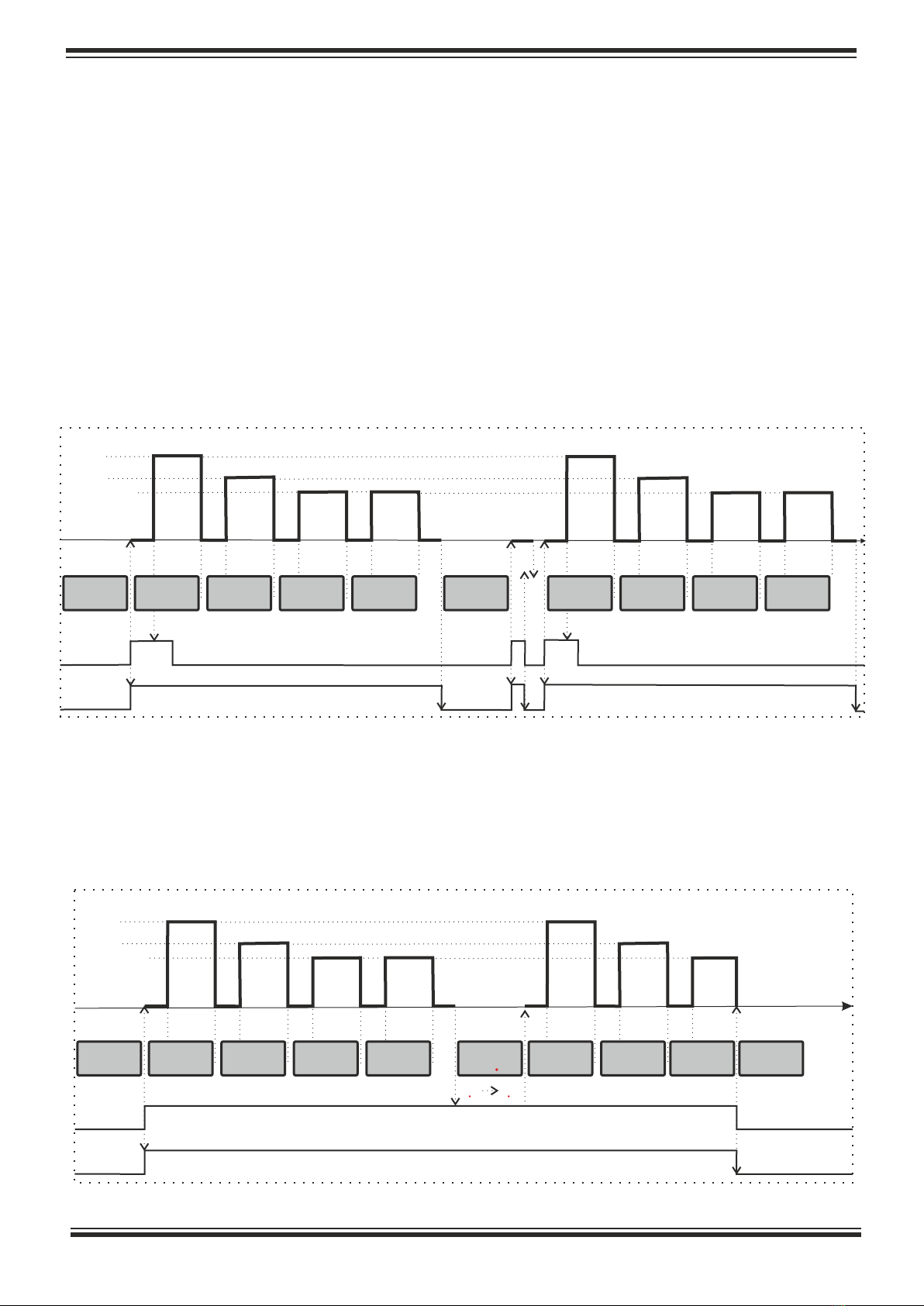
Multi-spark welding is implemented in order to achieve the best quality of
welding, especially for rounded items.
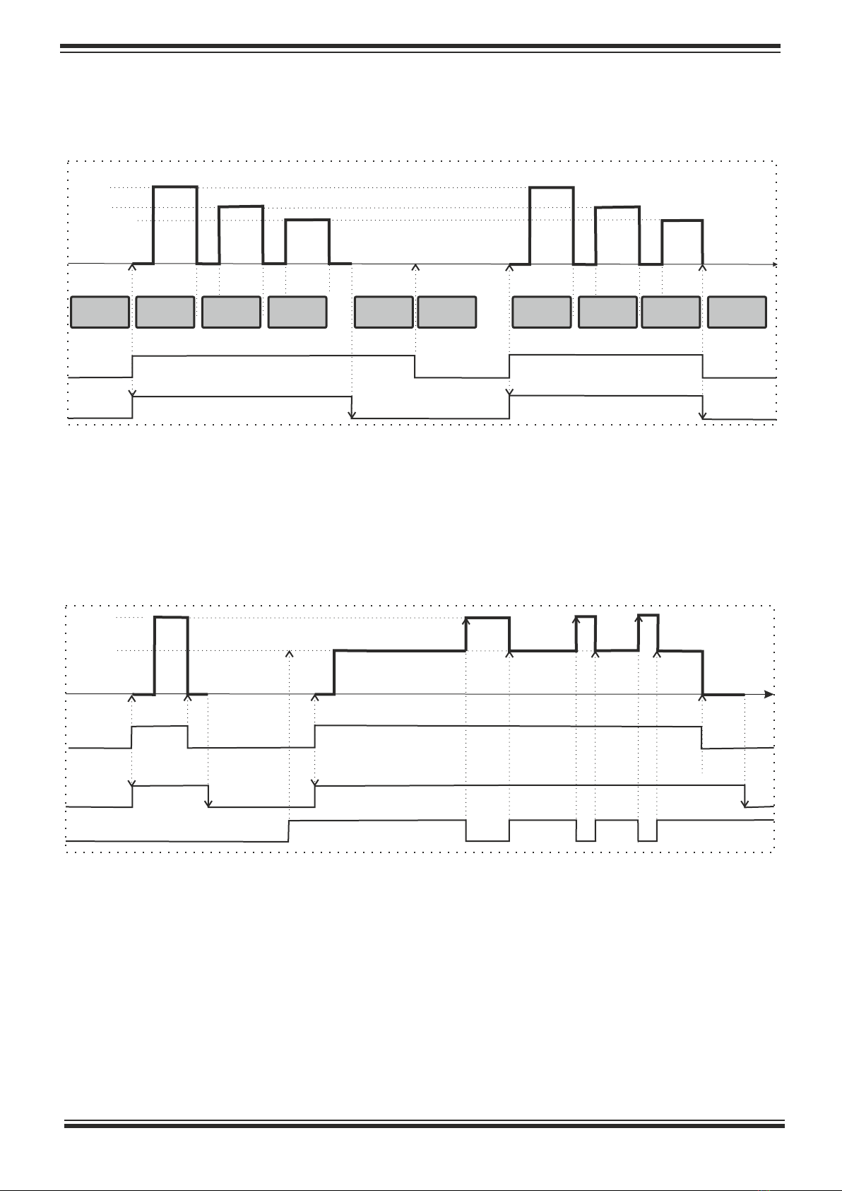
Five independent timers are provided to facilitate the process of welding:
pressing time (toF), weld time (ton), pause between multiple sparks (tP), cooling
time (tE) and delay time between welds (td) for repetitive welding only.
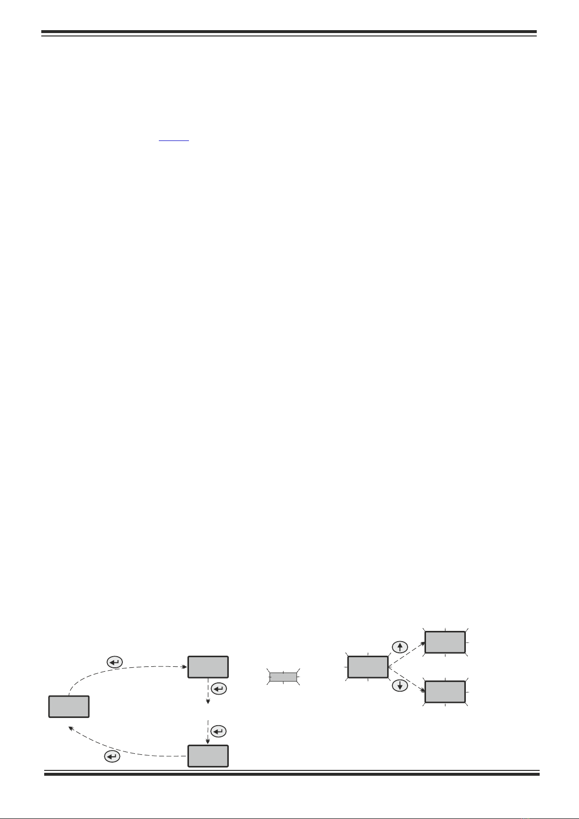
The controller’s display can switch between the following two states:
working and settings.
The output power, regulated by the PCN101ZP, is divided to 100 units
(percentage of the full power). The value of 0 means that the output of the
controller is off, whereas 100 means that it will transmit the full input power.
Introduction
Display of the controller
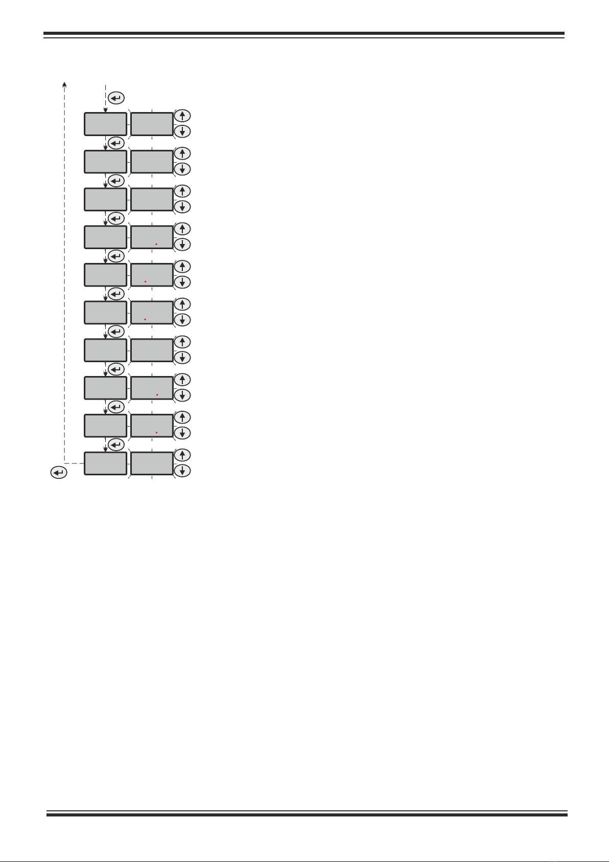
The ( ) button is used to switch between these two states. When in settings
8
state, the display will flash a mnemonic message with the parameter to be
changed by the user:
---
SP
Sb
70
69
71
parameter’s mnemonics
followed by parameter’s value
appear in flashing mode
after the last parameter
back to working state
navigate throughout
all parameters...
the value of the selected parameter
can be changed by arrow keys
Working state
to settings state

3
** parameter available only for repetitive welding mode Sb =1
SP
Sp2
Sp3
toF
ton
tp
ni
te
td
Sb
70
50
10
20
120
052
4
10
50
1
output power value for the first spark(impulse)
0-100 (% of full power)
output power value for the second spark(impulse)
0-100 (% of full power)
output power value for sparks 3-99
0-100 (% of full power)
pressing time before actual welding
0.0-25.0 (seconds)
weld time for each spark
0.00-2.50 (seconds)
pause between sparks
0.00-2.50 (seconds)
number of sparks for multi-spark welding
0-99
cooling time after weld
0.0-25.0 (seconds)
delay between two welds in repetitive welding (Sb=1)
0.0-25.0 (seconds)
welding mode according to the digital input
0-3
Working state
*
*
*
*
*
**
* parameter not available in continuous welding mode Sb = 3
When the digital input is ON, the display will show the currently transmitted
output power units. The welding LED (RUN) will blink during the pressing and cooling
phase. Both (K1) and (RUN) LEDs will be illuminated during the actual welding.
When there is a pause in repetitive welding mode (SB=1), the display will read the
remaining time before the start of the next welding (Fig.2).
Powering up the controller with the digital input ON will invoke collision and
the display will show --o as a notification for the user to switch off the input. Collision
will occur also, if the input is re-enabled during the cooling phase of the previous
welding.

Welding control modes
The following four welding modes with respect to the digital input are available,
depending on the value of Sb parameter:
1 - (Repetitive welding) It is necessary to keep digital input ON for the whole
process of welding. Releasing the input will stop the repetitions and bring the
controller to ready state. After one weld is completed, there will be a delay of td
seconds before the next one starts:
The option for multi-spark welding is available for all modes except for
continuous welding. In order to use it, set ni >1 for the number of sparks(impulses)
when welding non-flat items. In this case, the user can set different values for the
power of the first and second spark.
0 - (Trigger on initial pressing) It is necessary to keep digital input ON for
the whole phase of pressing (timer toF), after that the welding process will continue
straight to the final cooling phase regardless of the input state. A new welding will be
triggered only from ready state of the controller, i.e. previous welding finished and
digital input OFF:
Fig.1 Timing diagram for welding trigger on initial pressing, ni = 4 and Sb = 0
* The second input triggering does not start real welding
SP
SP2
toF toFtP tPtP tPtP tPtE tEton tonton tonton tonton ton
--- 70 70 50 50 40 40 40 40
---
input Din
toF
output+K1
70
---
4
*
*
*
SP
Sp2
Sp3
toF toFtP tPtP tPtP tEton tonton tonton tonton
Fig.2 Timing diagram for repetitive welding mode, ni = 4 and Sb =1
the digital input is released at the end of third spark of the second weld
td
delay
--- 70 70 50 50 40 40 40 ---
23
input Din
output+K1
23 00
Sp3

2 - (2-step welding) It is necessary to keep digital input ON for the whole
process of welding. Releasing the input will stop the process and bring the controller
to ready state. A new welding will be triggered only from ready state of the
controller, i.e. previous welding finished and digital input OFF:
3 - (Continuous mode) In this mode the welding process continues without
sparks with output power of SP. Releasing the input will stop the weld and finish the
cooling phase of the process. A new welding will be triggered only from ready state
of the controller, i.e. previous welding finished and digital input OFF:
* When in continuous welding mode with the digital input ON, the display will
show the current output power SP, that can be changed directly by the arrow keys.
This helps the user find the suitable values in this welding mode, especially in the
process of seam sealing.
5
Fig.3 Timing diagram for 2-step welding mode, ni = 3 and Sb = 2
The second release of the digital input will stop welding at the third spark
SP
Sp2
Sp3
toF toFtP tPtP tPtEton tonton tonton ton
--- 70 70 50 50 40 40
--o ---
---
input Din
output+K1
SP*
toF tE tE
input Din
Fig.4 Timing diagram for continuous welding mode, Sb = 3
SP
toF
output+К1
*change of SP by the arrow keys

PCN101ZP is a panel-mount controller with a LED display, suitable for operator
panels of electrical units. The cutout slot for mounting should be a
(45+0.3)x(92+0.3) mm rectangle. To secure the controller on the panel, use the
attaching brackets and screws. The connector pinout of the controller is pictured on
the rear panel.
The connecting wires must be isolated and have minimal cross sectional area
of 0.35-0.75 mm² for G1;K1 and G2;K2 control circuits. The rule to remember for the
2
power wiring is 6А/mm . The following diagrams illustrate single-phase ( ) and Fig.5
two-phase ( ) connections to a standard dual thyristor module:Fig.6
Mechanical installation and wiring
Make sure the thyristor module is well ventilated for power rates above 500W!!!
6
400VAC
Fuse
~
-
+
Pedal
230VAC
Fuse
~
-
+
Pedal
Welding transformer
230VAC
VEMA DE S I G N LT D .
U 230 / 50 Hz; Pн=2.4 VA
202 1 г.
IP20 TC
04 П2 7 058 - 04
N
o
230 V
AC
1 2 3 4 5 6 7 8 9 10 11
PCN101ZP
G1 K1 G2 K2 0V Din
VEMA DE S I G N LT D .
U 230 / 50 Hz; Pн=2.4 VA
202 1 г.
IP20 TC
04 П2 7 058 - 04
N
o
230 V
AC
1 2 3 4 5 6 7 8 9 10 11
PCN101ZP
G1 K1 G2 K2 0V Din
Fig.5 Connections diagram for single-phase power supply
Fig.6 Connections diagram for two-phase power supply
Welding transformer
Table of contents
Popular Welding Accessories manuals by other brands

ESAB
ESAB Eye-Tech 10-12 Select instructions

Parkside
Parkside 85053 Operation and safety notes

Abicor Binzel
Abicor Binzel MIG ROBO operating instructions

Miller Electric
Miller Electric MOTORIZED SLIDE MSC-2 owner's manual

Tregaskiss
Tregaskiss TOUGH GUN CA3 Series owner's manual

FRONIUS
FRONIUS TransPocket 1400 Operating instructions/spare parts list