Vemco BR2300 Installation instructions manual

Mounting Guide
Vemcount Counter BR2300
The Vemcount counter unit is a complete traffic counting unit where the sensor and counting/
communication computer is built into one unit, that is ready to be mounted to the ceiling where counting is
needed. BR2300 can be mounted in heights from 240 cm to 1280 cm.
Your counter in this package has minimum mounting height on 240cm and max mounting height of 460cm
(If it is higher than written on the line above please contact our support team immediately)
Mounting Guidelines
For installations where there is only one sensor needed then the placement should be in the middle of the
entrance, for two or more sensors please see the last page of the mounting guide for specific information.
Sensor should be oriented such that the LEDs are pointed towards the store interior and the
Ethernet cable is pointed towards the store exterior unless obstructions prohibit it.
Brackets should be used in plaster ceiling where screws can be securely attached into the ceiling.
If bracket are used in drop ceilings, some sort of backing (metal t-bar or plywood) must be used behind the
ceiling tile to prevent the sensor from falling out should the ceiling tile get wet or rot.
Ceiling mounting bracket Wall mounting bracket

Depending on the shop and its entrances you can use ceiling (vertical wall) mounting bracket or wall
bracket (horizontal mounting). In 95% of all shops a vertical bracket will be used! Use horizontal bracket
only in cases where there is not possible to mount sensors directly to the ceiling.
PoE should always be placed in the network closet close to the router. PoE can send power up to max 100M
to the sensor device.
To make it counts precise please make sure that the sensor has free view of the entrance.
Counter should be placed about 1-1,5M in distance from the entrance and mounted in the middle of the
entrance. The marked area must be free of moving objects such as doors, posters etc. Stable objects such
as walls, tables, exhibition objects etc. are ok.

Post installation
When the installation and cabling is correctly done, connect the PoE to the network and power-outlet.
Counter should boot up now, which takes about two minutes, during this LED’s will be flashing. When
Counter is connected to the network correctly then green light will flash constantly and your installation is
done correctly. If green light is not flashing after some minutes please read troubleshooting.
Use some extra time to make the installation perfect! Check that there are no loose ends. All cabling should
be hidden as much as possible. Your work will be recorded (in a form of a picture of the sensor installation)
before opening and sent to us for review!
LED Light Functions
Status LED 1 - Blinks during the boot sequence.
Status LED 2 - Blinks at a 3 second interval to indicate the sensor connection status with either a time sync
server or data server. If the LED is amber the sensor cannot connect with either server, if the LED is green
the sensor can connect to at least one of these servers.
Status LED 3 - If this LED is red, the unit has reverted back to its default factory settings and has an IP
address of 192.168.1.7
The normal startup sequence is as follows:
1. All LEDs blink green.
2. Two LEDs illuminate red for 5 seconds.
3. Three LEDs illuminate red for 10 seconds.
4. Three LEDs blink amber.
5. One LED illuminates green for 1 second indicating the startup of the Brickstream boot sequence.
6. One LED illuminates green and one LED illuminates amber for 15-20 seconds.
7. The middle LED blinks green or amber to indicate the server connection status.

Troubleshooting.
Counter is not starting or no lights are flashing - Check that PoE is connected to the power-outlet test the
power and network cabling connection from the PoE to the counter.
Counter is flashing yellow - Check that counter is connected to the network with an Internet connection
(router). Inbound port 80 in the router must be open (Normally port 80 is always open). When connection
is checked please reboot the sensor and wait until green light is flashing.
Network Description
The counter transmits its data to Vemcount servers and from there the reports are made available to
customers worldwide.
For this system to function, it must be connected to an Ethernet network with access to Internet and
preferably a DHCP server.
If DHCP is not available, or if a fixed IP-address is needed, the network information must be send to our
support team prior to the shipping.
If the Internet access is via a PROXY, then please open for direct connection to Vemcount server:
http://data.vemcount.com. The counter unit cannot be setup to use PROXY.
Inbound ports (80, 123, 2000 and 3000)
All inbounds ports are normally opened as standard on routers. If for some security reasons all inbound
ports are closed please open port 80, 123, 2000 and 3000. These ports are used for remote adjustments on
the counter, timeserver sync and for logs. Bandwidth usage from the unit is very low - a few kB every 15
minutes.
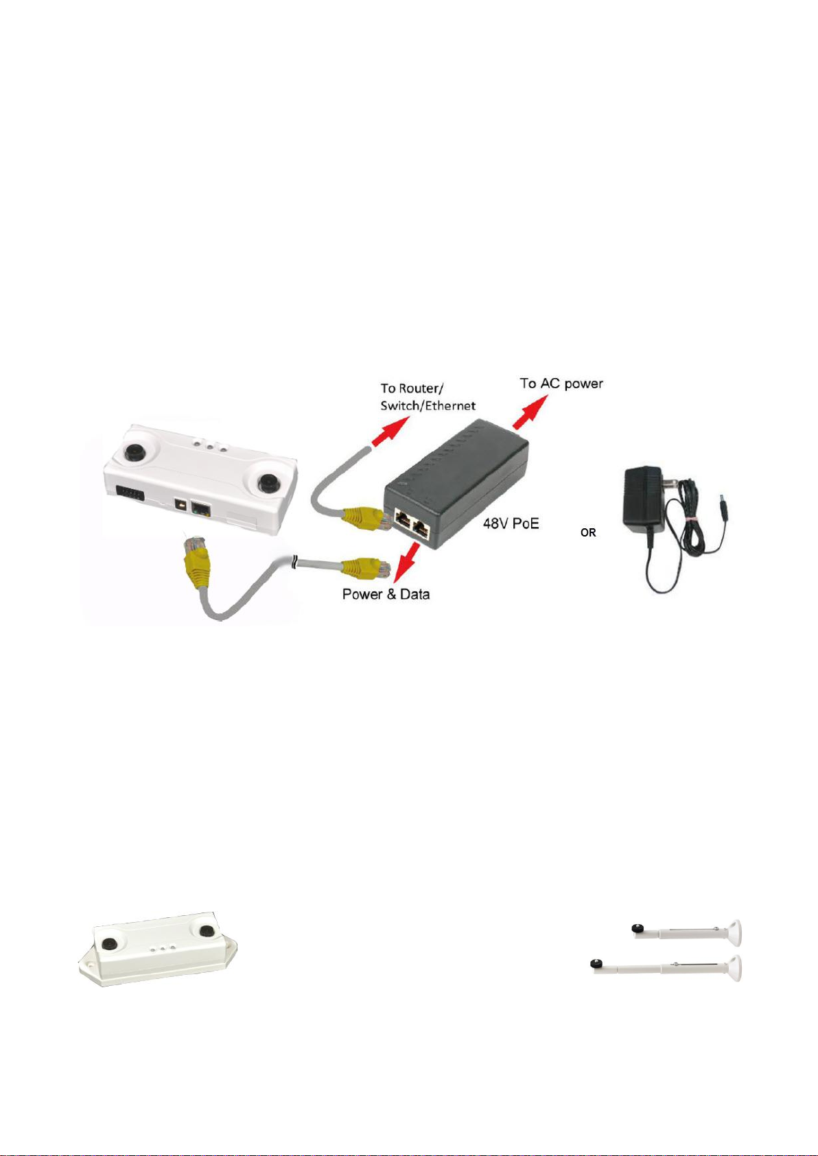
Power to the unit is provided by Power-Injection on the Ethernet Cable.
If of any reason counter cannot get connection to the server or there are any other errors that are not
explained in this manual please feel free to contact us at any time by mail or phone.
VEMCOUNT
Brovadvej 23
7000 Fredericia
Denmark
T. +45 76221146
Thank you for choosing VEMCOUNT

Mounting Guidelines for two or more sensors
The distance between the sensors should be as defined below. Please locate the middle of the entrance
and do the required measurements from there.
Table of contents