Vendo Sanden HFD000006 Operating manual

SANDENVENDO AMERICA INC
1213686J ECN 57413 1
HOT FOOD DISPLAY
Technical Service Manual
MODELS HFD000006 & 7
HFDC00002 & 3
HFDM00002
HFDH00001 thru 3
HFDHC0001 thru 10
Table of Contents
Commitment to Safety…….….…...….…2
Safety Warnings…….……..…….............3
Parts..…….…………………………….......4
Operation……………………..….………...8
Troubleshooting……………..…….…....12
Controller Connections..……..…..….…13
HFD000006, HFD000007
HFDC00002, HFDC00003
HFDM00002
HFDH00001,2,3
HFDHC0001,2,3,4,5,6,7,8,9,10

SANDENVENDO AMERICA INC
1213686J ECN 57413 2
A COMMITMENT TO SAFETY
The SandenVendo is committed to safety in every aspect of our product design.
SandenVendo is committed to alerting every user to the possible dangers involved in improper
handling or maintenance of our equipment. The servicing of any electrical or mechanical
device involves potential hazards, both to those servicing the equipment and to users of the
equipment. These hazards can arise because of improper maintenance techniques. The
purpose of this manual is to alert everyone servicing SandenVendo equipment of potentially
hazardous areas, and to provide basic safety guidelines for proper maintenance.
This manual contains various warnings that should be carefully read to minimize the risk of
personal injury to service personnel. This manual also contains service information to insure
that proper methods are followed to avoid damaging the Hot Food Display (HFD) or making it
unsafe. It is also important to understand these warnings are not exhaustive. SandenVendo
could not possibly know, evaluate, or advise of all of the conceivable ways in which service
might be done, nor can SandenVendo predict all of the possible hazardous results. The
safety precautions outlined in this manual provide the basis for an effective safety program.
Use these precautions, along with the service manual, when installing or servicing the HFD.
We strongly recommend a similar commitment to safety by every servicing organization. Only
properly trained personnel should have access to the interior of the machine. This will
minimize the potential hazards that are inherent in electrical and mechanical devices.
SandenVendo has no control over the machine once it leaves the premises. It is the owner or
lessor’s responsibility to maintain the Hot Food Display in a safe condition. Follow all Safety
Rules and Safety Warnings in this manual. If you have any questions, please contact the
Technical Services Department of SandenVendo.
SAFETY RULES
•Read the Safety Warnings before installation or service.
•Test for proper grounding before installing to reduce the risk of electrical shock and fire.
•Turn off power switch and disconnect power cord from wall outlet before servicing.
•Use only fully-trained service technicians for Power-On servicing.
•Use adequate equipment when moving the HFD.
•Use only authorized replacement parts.
•Be aware of inherent dangers in rocking or tipping the HFD.
•Always turn power off before plugging or unplugging HFD to wall outlet.
FOOD FOR THE HOT FOOD DISPLAY
The HFD, HFDM, and HFDH units are design to hold unwrapped, wrapped, and boxed
food. The HFDHC is designed to hold wrapped and boxed food. Hot food displays
are not designed to heat cold food - put only hot food in the hot food display.

SANDENVENDO AMERICA INC
1213686J ECN 57413 3
SAFETY WARNINGS
The HFD is for indoor use only. Do not use near water or in condensing humidity.
To prevent electric shock or fire, do not kink, pull, or pinch the power cord, and insure no
equipment is resting on the power cord. If the power cord is damaged, unplug and replace.
Do not connect with other plugs. Do not use an extension cord.
When unplugging, first turn off the power switch. Then pull the plug at the end of the power
cord, not by pulling the power cord, since the cord can be damaged, overheat, and cause a
fire.
Do not spray water on the HFD. It may cause an electric shock or fire.
Do not touch the power plug, switches, or other electrical parts with wet hands. It can cause
an electric shock.
Periodically check that the plug is pushed in all the way.
To prevent injuries due to falling objects, liquid spills, electric shock or fire, do not place heavy
objects or liquid-filled objects on top of the HFD.
To prevent electric shock or fire, do not use volatile or flammable products in or near the HFD.
When moving the HFD: turn the HFD off, unplug, and allow the unit to cool. To prevent glass
breakage and injury, do not push on the glass. Also, use proper equipment and lifting
techniques. Insure the product doesn’t tip while it is being moved.
If a lamp or any glass cracks or breaks, turn off the power and discard all food in the HFD.
Replace lamp and / or glass. Remove all glass fragments. Carefully inspect all surfaces,
corners, and gaskets to insure all glass fragments have been removed before returning HFD
to service.
Keep HFD out of direct sunlight and away from heat sources.
Do not hang from the door –this may cause injury or electric shock.
Turn off and unplug HFD before servicing, and let HFD cool before cleaning or servicing.
Use proper tools while servicing.
Use only authorized replacement parts.
The HFD temperatures are factory set to meet NSF food safety requirements. Changing
temperature settings may adversely impact food safety.
The lamps are an integral part of the food heating system. If a lamp is not illuminated, the
temperatures may not be maintained for food safety.

SANDENVENDO AMERICA INC
1213686J ECN 57413 4
PARTS
(Vertical slide rail
same each side)
Shelf edge gasket
(same each shelf)
Lamp
Socket
Lamp
Rear door
and slides
Bottom
Heater
Plate
Side
Gasket
Bottom
Heater
Plate
Front
Gasket
Controller
Breaker
switch
Power cord
Front door gaskets
Shelf assemblies
Item Part # Description
1 1158489 Gasket, Door, Side
2 1158477 Gasket, Door, Upper
3 1158491 Gasket, Door, Lower
4 1201293-2 Controller
5 1207087 Heater Kit (not shown)
6 1207441 Shelf Assembly, Upper Left
7 1207465 Shelf Assembly, Middle Left
8 1207415 Shelf Assembly, Bottom
9 1207476 Shelf Assembly, Middle Right
10 1207453 Shelf Assembly, Upper Right
11 1158685 Gasket A
12 1158696 Gasket B
13 1159513 Lamp Socket
14 1159525 Xenon Heating Lamp
15 1255614 Power Cord Plug
16 1257854 Circuit Breaker, 20 Amp
17 1194238 Rear Door, HFD
18 1158673 Slide Rail, Lower (Horizontal)
19 1158969 Slide Rail, Side (Vertical)
20 1159604 Shelf Edge Gasket
21 1180812 Fan, HFD (HFD 7 only)
1
2
3
1
6
7
10
9
8
11
12
15
16
4
17
18
19
14
13
Shelf Assembly Connector Colors
Item Connector Color Description
6 White Shelf Asy, Upper Left
7 Black Shelf Asy, Middle Left
8 Red (left) Green (right) Shelf Asy, Bottom Shelf
9 Yellow Shelf Asy, Middle Right
10 Blue Shelf Asy, Upper Right
20
22
HFD000006, HFD000007
See last page for Controller Connections
for electrical component part numbers

SANDENVENDO AMERICA INC
1213686J ECN 57413 5
*Note when ordering replacement doors for units without the center door handles use
kit part number 1262106 so you get a set of matching doors (both left and right).
Rack
Rack
Combo Serve Front Door & Shelf Parts
Item Part # Description
1* 1259989 Left Door w/ Center Handle Assembly
2* 1259989-1 Right Door w/ Center Handle Assembly
3 1185603-1 Frame Gasket (Horizontal, 2x)
4 1185603-2 Frame Gasket (Vertical, 2x)
5 1187405 Damper (one each side)
6 1202273 Extension Spring (one each side)
7 1199716 Rack, Top/Middle Shelf (not shown, 4x)
8 1199728 Rack, Bottom Shelf (not shown, 2x)
9 1201311 Shelf Guard (4x)
10 1207751 Shelf Assembly, Upper Left
11 1207775 Shelf Assembly, Middle Left
12 1207786 Shelf Assembly, Middle Right
13 1207763 Shelf Assembly, Upper Right
14 1219634 Rear Door Keep-Closed bracket (not shown)
15 1207087 Heater Kit (not shown)
16 1201293-3 Controller, HFDC (not shown)
1
2
6
5
7
8
9
3
4
HFDC00002, HFDC00003
13
12
11
10

SANDENVENDO AMERICA INC
1213686J ECN 57413 6
1207087 Heater Kit (not shown)
On back of unit (not shown):
1257854 Breaker, 20A
1255614 Power Cord
1177435 Front
Gasket (not shown)
1207488 Bottom
Shelf Assembly
1178038 Vertical Rear
Gasket (not shown)
1177198
Front Door
1203125 Caution
Hot Label
1182055 Middle
& Upper Shelf
Rack, Black
1158685
Side Gasket
1178052 Horizontal
Rear Gasket
1166955 Side Glass (no decal)
1165366 Right Decal
1201293-1 Controller
1178854 Lamp Guard
1182066 Bottom
Rack, Black
1178798 Shelf Guard
1165355 Left Decal
1207555 Shelf
Assembly
HFDM00002
1207567 Shelf
Assembly
See last page for Controller Connections
for electrical component part numbers

SANDENVENDO AMERICA INC
1213686J ECN 57413 7
1226399 Bottom 2
Racks (not shown)
1226352 Top/Middle
2 Racks per shelf
(not shown)
1226236 Shelf Guard
1229516 Solid Front Glass
1158696-1 Front Gasket
1242342 Pan Restraint (2x)
1185603-4 Vertical
Frame Gasket
1253573 Lt Front Door w/center handle (HFDHC0009,10)
*For HFDHC0001 through HFDHC0008, use kit p/n
1262114 to get a matching door set (both left and right).
1226272 Side Glass
(no decals)
1201293-4
Controller
1158696-2 Side Gasket
1253573-1 Rt Front Door w/center handle (HFDHC0009,10)
*For HFDHC0001 through HFDHC0008, use kit p/n
1262114 to get a matching door set (both left and right).
1226094 Rear Door
Models & Heaters
1242342 Pan Restraint (2x)
HFDHC0001,2,3,4,5,6,7,8,9,10
See last page for Controller Connections
for electrical component part numbers
1185603-3 Horizontal
Frame Gasket

SANDENVENDO AMERICA INC
1213686J ECN 57413 8
OPERATION
Display and Keypad
Timer Setting and Operation
Note: to help prevent keypad damage, push keypad buttons only with finger or thumb; do not use
fingernail, utensil, tool, pen, or other object.
Circulation fans may be turned on or off by the switch at the top rear of the HFD (HFD 7 and HFDC).
Normal Operation
Pressing the I/O button turns the HFD on or off. When controller is off, all lamps, heaters, displays
and indicators are off. Front on/off button (HFDC only): press and hold for 5 seconds to turn the
HFDC on or off.
Timers
Holding down the TIME button, then pressing a Timer button, turns off the timer. When a timer is off,
pressing the Timer button once sets the countdown timer to the value preprogrammed into the
controller.
Pressing the Timer button again within three seconds (while the indicator next to the button is
blinking) sets the timer to 30 minutes.
Each successive press (within three seconds) adds 30 minutes to the time, up to 4 hours.
At 4 hours, the next button press cycles the timer back to 30 minutes again.
Once the timer is activated, the LED next to the shelf timer button stops blinking and stays on.
The display then reverts to HFD internal air temperature.
While a timer is on, pressing a timer button displays the remaining time for 4 seconds, then shelf
actual temperature (not the setpoint) for 4 seconds, and then the display reverts to the internal
ambient temperature display.
At 15 minutes remaining time, the LED turns yellow.
When no time remains, the LED turns red, plus an audible alarm sounds. Shelf heaters stay on.
Pressing the timer button next to the blinking red LED clears the alarm and restarts the timer.
Converting Temperature from °F to °C (or °C to °F)
With controller power off, hold down the TIME button, then press and hold the I/O button until the
display comes on. The display shows the firmware revision (example 4.11).
Press and release the TIME button to change from °F to °C (or °C to °F).
Push the I/O button to turn on the HFD and lock in this setting.
Ambient Temperature Display
I/O button
USB port
Timer adjustment: Use buttons to adjust
shelf temperature and timers down or up
Upper left shelf
(except HFDM)
Middle left shelf
(except HFDM)
Upper right shelf
Middle right shelf
Lower right shelf
TIME
button
Lower left shelf
LEDs for timers and adjustment

SANDENVENDO AMERICA INC
1213686J ECN 57413 9
To turn the ambient temperature display on or off: with the controller on, press and hold the Time
button and press the I/O button. (This feature is disabled in firmware revision 4.01).
Front Door
If the front door is opened (HFD6 and 7 only), the controller turns off only the lights. The display
reads "OPEn". After closing the front door, the lights turn on, and the display reverts to internal
ambient temperature.
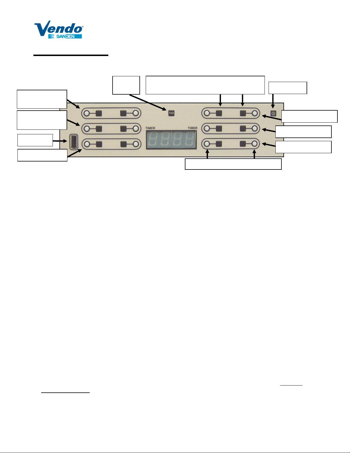
Heater Temperature Adjustment
Push the I/O button to turn the unit off. The lights and heaters turn off.
With controller power off, hold down the TIME button, then press and hold the I/O button until the
display comes on. The display will show the firmware revision.
Push either of the two buttons corresponding to the shelf that you wish to change the temperature.
Both lights on either side of the buttons will begin blinking.
Push and hold the button on the left to decrease the temperature (shown on the display).
Push and hold the button on the right to increase the temperature (shown on the display).
Repeat the procedure using the buttons that correspond to each of the six shelves (for HFD6 & 7), or
four shelves (HFDM).
Once the temperatures are adjusted for each of the separate zones, push the I/O button to lock in
the new temperature settings and to turn the HFD back on (the lights in the HFD will come on).
Error Codes
E30 Internal ambient thermistor open circuit
E60 Upper left shelf thermistor open circuit (except HFDM) E63 Upper right shelf thermistor open circuit
E61 Middle left shelf thermistor open circuit (except HFDM) E64 Middle right shelf thermistor open circuit
E62 Lower left shelf thermistor open circuit E65 Lower right shelf thermistor open circuit
E90 Unable to read USB drive (check vendo.cfg for file format error)
E70 Upper left shelf not heating (except HFDM) E73 Upper right shelf not heating
E71 Middle left shelf not heating (except HFDM) E74 Middle right shelf not heating
E72 Lower left shelf not heating E75 Lower right shelf not heating
Clear the error by powering off the unit, correcting the problem, and turning the unit on again.
Programming using USB drive
The file name must be vendo.cfg and be saved on the root directory of the USB drive. The file may
be edited using Notepad.
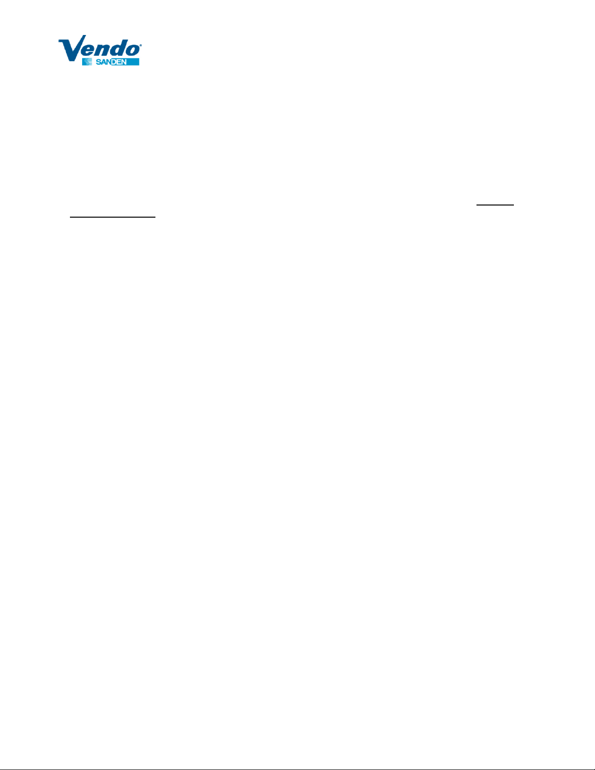
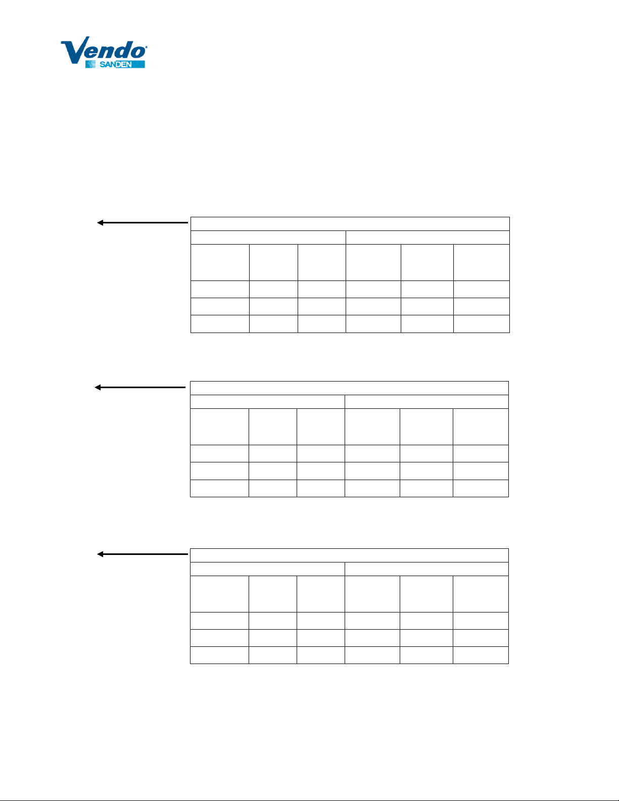
Temperature and Timer Programming Format and Download
SV01 Must be SV01
001h This is configuration 001, h for standard HFD (n for HFDM, c for HFDC, etc.)
UL:235,2:00,0:30 Upper Left shelf, set to 235ºF, left timer 2 hours, right timer 30 minutes
ML:235,2:00,2:00 Shelf temperatures may be set between 100 and 255ºF
LL:220,1:00,2:00 Setting a shelf temperature to 000 turns off that shelf
UR:235,2:00,1:00 Shelf temperature must be 3 digits, always in ºF
MR:235,2:00,2:00 Each timer may be set between 0:30 and 4:00
LR:220,1:00,2:00
CF:1 1 displays ºF, 0 displays ºC
DA:1 1 turns on controller ambient display, 0 turns display off
DS:1 Front door switch –1 for HFD6 & 7; all others 0.
Any text may follow here

SANDENVENDO AMERICA INC
1213686J ECN 57413 10
There can be no spaces or blank lines. A line is terminated by pressing Enter. The only variables
that are allowed to change are the date code, shelf temperatures and times, the 0 or 1 after CF:,
DA:, and DS:, and the comment at the end of the file.
With the HFD off:
1. Insert the flash drive in the controller’s USB port.
2. Turn on the controller. The configuration will load in less than 5 seconds.
3. The display will show the configuration code (example: 001h) from the vendo.cfg file.
4. Pull the flash drive out of the controller (controller may remain on).
Factory Controller Configurations
SV01
001h
UL:235,2:00,1:00
ML:235,2:00,2:00
LL:220,1:00,2:00
UR:235,1:00,1:00
MR:235,2:00,2:00
LR:220,2:00,1:00
CF:1
DA:1
DS:1
SV01
001n
UL:000,2:00,2:00
ML:000,2:00,2:00
LL:245,2:00,2:00
UR:245,2:00,2:00
MR:245,2:00,2:00
LR:245,2:00,2:00
CF:1
DA:1
DS:0
SV01
001c
UL:240,2:00,2:00
ML:240,2:00,2:00
LL:240,2:00,2:00
UR:240,2:00,2:00
MR:240,2:00,2:00
LR:240,2:00,2:00
CF:1
DA:1
DS:0
HFDM 2
Left Side
Right Side
Heater
Setpoint
ºF
Left
Timer
Right
Timer
Heater
Setpoint
ºF
Left
Timer
Right
Timer
OFF
2:00
2:00
245
2:00
2:00
OFF
2:00
2:00
245
2:00
2:00
245
2:00
2:00
245
2:00
2:00
HFD 6 & 7
Left Side
Right Side
Heater
Setpoint
ºF
Left
Timer
Right
Timer
Heater
Setpoint
ºF
Left
Timer
Right
Timer
235
2:00
1:00
235
1:00
1:00
235
2:00
2:00
235
2:00
2:00
220
1:00
2:00
220
2:00
1:00
HFDC 2
Left Side
Right Side
Heater
Setpoint
ºF
Left
Timer
Right
Timer
Heater
Setpoint
ºF
Left
Timer
Right
Timer
240
2:00
2:00
240
2:00
2:00
240
2:00
2:00
240
2:00
2:00
240
2:00
2:00
240
2:00
2:00

SANDENVENDO AMERICA INC
1213686J ECN 57413 11
HFDH and HFDHC
SV01
00HC
UL:245,2:00,2:00
ML:245,2:00,2:00
LL:245,2:00,2:00
UR:245,2:00,2:00
MR:245,2:00,2:00
LR:245,2:00,2:00
CF:1
DA:1
DS:0
HFDH and HFDHC
Left Side
Right Side
Heater
Setpoint
ºF
Left
Timer
Right
Timer
Heater
Setpoint
ºF
Left
Timer
Right
Timer
245
2:00
2:00
245
2:00
2:00
245
2:00
2:00
245
2:00
2:00
245
2:00
2:00
245
2:00
2:00

SANDENVENDO AMERICA INC
1213686J ECN 57413 12
TROUBLESHOOTINGUnplug unit before servicing
Symptom
Possible Cause
Remedy
Unit does not turn
on
Power cord unplugged
No power at outlet
Plug HFD cord in outlet.
Check voltage at outlet (115VAC)
HFD circuit breaker off
Turn on breaker. HFD6 & 7: remove lower rear cover
to access breaker.
Internal power cord
disconnected
Check resistance across plug, ensure the breaker is
on, measure resistance across plug terminal, line and
neutral, should be about 160Ω.
Front glass door open
HFD6 & 7 only: Controller should read “OPEn”. Shut
front glass door, press power button on controller to
initialize.
One or more
Xenon lamps is off
Bulb blown
Check at terminal for resistance of about 44Ω.
Check to ensure bulb is securely installed.
Replace blown bulb(s).
HFD display
ambient does not
reach 150°F
One or more heater
plates not reaching
temperature. An error
(E70 to E75) may be
displayed on controller.
HFD, HFDC and HFDM need 30 minutes to reach
temperature. HFDH and HFDHC needs at least 1
hour.
Check plate temperature at controller (see controller
operation).
One or more Xenon
lamp not functioning
Check at terminal for resistance of about 44Ω.
Check to ensure bulb is securely installed.
Replace blown bulb(s).
E60 to E65 error
Heater thermistor open
circuit
Pull out controller, disconnect corresponding heater
connector. If resistance between red wires is greater
than 100k ohms, check cause of open circuit. Heater
may need replacing.
Heater plate not
heating. Possible
E70 to E75 error.
Fuse blown on
controller
Remove controller and check fuses.
Wires disconnected
Remove controller and check all connections at
controller.
Failed heating element
Check resistance across white and black wires from
heater. Resistance should be about 94 ohms at room
temperature (for HFDH and HFDHC units, see page
7). If circuit is open, heater needs replacing.

SANDENVENDO AMERICA INC
1213686J ECN 57413 13
Lower
Right
Heater
Lower
Left
Heater
CONTROLLER CONNECTIONS
Left / Right as viewed from the controller side
1087074
Switch
1206526 Thermistor
Extension Cable
HFDM only (not shown)
1180794 Fan Cable
1180812 Fan (2x)
1257854
Breaker
Middle
Left
Heater
Top
Left
Heater
Middle
Right
Heater
Top
Right
Heater
1250396 Heater 6x: HFDH, HFDC
1250396 Heater 4x: HFDM
For HFDHxxxx and HFDHCxxxx heaters, see summary on page 7
1232436
Remote on/off cable
1164041
Thermistor
1206552
Door Switch Cable
1206564 Lamp Cable 6x: HFD, HFDC
1206564 Lamp Cable 3x: HFDM
1232444 Lamp Cable 6x: HFDH, HFDHC
1159513 Lamp Socket 6x (HFDM 3x)
1159525 Lamp 6x: HFD6 & 7, HFDC
1178877 Lamp 3x: HFDM
1178877 Lamp 6x: HFDH, HFDHC
1255622
Internal
Power
Cord
1255614
External
Power Cord
OR
1259326
External Power
Cord for
HFDHC0007,8
& HFDH00003
1201293-1 HFDM Controller
1201293-2 HFD Controller
1201293-3 HFDC Controller
1201293-4 HFDH/C Controller
1158065
Front
Door
Switch
Except
HFDM
HFD7 and HFDC only (not shown)
1187878 Cable, Fan with Switch
1187843 Rocker Switch
1180812 Fan (2x)
7x 1127484 Fuse
3.15 amp slow blow
250V 5x20 mm
Newer model
controllers do not
have replaceable
heater fuses
HFDH and HFDHC (not shown)
1226174 Lamp to Fan Cable (2x)
1180812 Fan (2x)
(HFDC only)
(HFD6 & 7 only)
NEMA
5-15P
NEMA
5-20P

SANDENVENDO AMERICA INC
1213686J ECN 57413 14
Older controller appearance and schematic below:

SANDENVENDO AMERICA INC
1213686J ECN 57413 15
CONTROLLER CONNECTIONS –Old models
Left / Right as viewed from the back side (controller side) of the HFD
1201218
1087074
Button
1202224
Harness,
Remote
On/Off
1159408
Light
Harness,
Top (2x)
1163898 Harness, Controller (HFD 3, 4, 5)
1202145 Harness, Controller (HFDC only)
1187878
Harness,
Fan with
Switch
1180812 Fan (2x)
1161921
Breaker
Fuses
F1 Upper Left Shelf
F2 Middle Left Shelf
F3 Lower Left Shelf
F4 Upper Right Shelf
F5 Middle Left Shelf
F6 Lower Right Shelf
F7 Lamps / Fans
1159574 Light
Harness, Shelf (4x)
1158908 Thermistor Extension Cable
This manual suits for next models
17
Table of contents