Venitem DOGE CT3 User manual

MA-SE-DCT3-01-02 Manual Doge CT3 eng rev2 Rev.4 Pagina 1 di 17
Alarm Bell/Control Panel
DOGE CT3
General Features:
DOGE CT3 is a sounder having functions of control panel for burglar alarm systems with 3 detection lines + 1 24 hours line.
The control panel can be managed via mechanical key or via Vela remote control (not given within)
The housing in ABS can locate a 12V 1.2 Ah or 12 V 2.2 Ah battery.
Connector for Vela remote control.
DOGE CT3 can be interfaced via the MCX or MCV optional boards for connecting from 1 to 4 inertial/vibration contacts.
High-luminous LED flash.
Easy programming via dip-switch.
3 immediate detection lines of N.C. or balanced type (selection by dip4)
1 detection line programmable as immediate or delayed (selection by dip2)
1 24 hours auto-protection line with immediate alarm also at disarmed system. The line can be excluded for servicing interventions
with the function of “block of auto-protection” opening the cover (see the paragraph “Service and Test”)
One partialization, by remote control, which excludes the zone 3
Flash at 3 luminous areas indicating the alarm zone
4 LED on board for detailed indication of anomalies during installation and service
Programming via dip-switch
2 programmable sounding
2 temporization for adjusting the input/output timing (input: 1 min or 30 sec; output: 1 min or 2 min)
2 temporization for adjusting the alarm duration (3 or 8 min) via dip1
Painted ABS cover, charged against UV
Protection against wall-tampering and cover-opening
Protection against polarity inversion
Discharged battery causes block of the horn and quick flashing further to block of the inputs reading, included key and remote
control in order to avoid false alarms
With very low battery the external LEDs switch off and the board resets
Indication of battery-resistance status. Indication of discharged battery.
Indication of broken horn
Indication delayed mains missing by Led on board, delayed on the terminal
Alarm relay output –free exchange for max 5 A. Can be used also with MiniDoge or other indoor siren, outdoor siren or telephone
dialer (optional)
Direct push-pull output for positive driving of the MiniDoge Led at totally or partially armed system
Alarm-memory, open collector output for driving a remote Led or telephone dialer
DOGE CT3 used in combination with Vela remote control (optional) leaves free the 2 relays of the receiver in order to connect one or
two channels of the telephone dialer for the silent alarm
Detectors supplying output with tension always present even at disarmed system
Input for external mechanical key. Can be interfaced with relay electronic keys
Circuit of recharge and control of back-up battery
2 auto-restorable fuses for separate protection of: board supplying and detectors supplying
Possibility of total arming by key and total or partial arming by remote control
Indication on flash of: armed system, partial, disarmed. First zone in alarm. Anomaly
0,5 A stabilized power supply, protected against short-circuit
Possibility of walk-test with attenuation on horn

MA-SE-DCT3-01-02 Manual Doge CT3 eng rev2 Rev.4 Pagina 2 di 17
Flashing of the front LEDs of the sounder
Pict. 1 ALARM ZONE 1, 2 e 3 Pict. 2 ALARM ZONE 24h and TAMPER
Pict.. 3 SYSTEM STATUS
(chart 1) Visualization of System Status
DIP5
Command
Flash status
OFF (default)
ARMED
All Leds flash 3 times and then switching off of the whole flashing
OFF (default)
PARTIAL
The central Led flash 3 times and then switching off of the whole flashing
OFF (default)
DISARMED
All Led switch on for 5 seconds and then switch off
ON
ARMED
All Led flash 3 times then flash of the central Led with 1 pulse and then pause
ON
PARTIAL
The central Led flash 3 times and then flash of the central Led with 2 pulses and
then pause
ON
DISARMED
All Led switch on for 5 seconds and then switch off
ON and OFF
ALARM
All Led flash with a pause. The number of flashes shows the zone in alarm
ON and OFF
TAMPER
All Led rotate
If the input/output time is activated, the Led, all of them or the central ones, flash until the end of the output time
If, during the input/output the zone 1 is open, the flash accelerates in order to show a pre-alarm condition
The flashing remains until the disarming of the system via the key
In case of anomaly all flashes accelerate.
TOTAL ARMING: 1 FLASH AND PAUSE
PARTIAL ARMING: 2 FLAHES AND PAUSE
Pict. 1
Pict. 2
Pict. 3

MA-SE-DCT3-01-02 Manual Doge CT3 eng rev2 Rev.4 Pagina 3 di 17
LEDs INSIDE THE SOUNDER
LED 1: LINES TAMPER, see also paragraph TAMPER.
(chart 2) LED Tamper LD5
Priority
CHART OF TAMPER AND NON-BALANCED ZONES INDICATION
Number of flashes
1
Zone1
1 FLASH
2
Zone 2
2 FLASHES
3
Zone 3
3 FLASHES
4
Zone 24h
4 FLASHES
5
Housing tamper or anti-foam
5 FLASHES
6
Anti-drilling (not given within)
6 FLASHES
0
Board awaiting change of inputs, as a consequence of reset
FIX ON
LED 2: ANOMALY OF LOCAL VISUALIZATION see also paragraph ANOMALIES
(chart 3) LED Anomalies LD1 - flashes
Priority
CHART OF INDICATION AND ANOMALIES
RED LED LD1
1
Speaker interruption
1 FLASH
2
Mains missing with immediate indication (tension of the supply unit less than
11,9V)
2 FLASHES
3
Battery not connected
3 FLASHES
4
Battery spoilt –Inside resistance higher than 2,5 Ohm
4 FLASHES
5
Low battery –tension lower than 10,5V
5 FLASHES
LED LD3: ALARM MEMORY, activated with the terminal MAL during the alarm and until the reset set by dip7
LED LD4: ALARM, activated with relay (terminals: A_C, AAC) for the alarm duration set by dip 1.
TAMPER AND
NOT-BALANCED
ZONES LED
ANOMALIES
LED
ALARM MEMORY
LED
ALARM
LED
RELAY
ALARM
1 2 3 4 5 6 7 8
SOUNDER
JUMPER TAMPER
FLASH
CONN.
.RECEIVER
VELA
CONN.
HORN AND
BATTERY CONN.
SUPPLY UNIT
CONN.
ANTI-FOAM
CONN
TAMPER COVER OPENING
TAMPER REMOVAL
FROM THE WALL
Pict. 4
J7 RELAY OUTPUT
SELECTION
NC -- NO

MA-SE-DCT3-01-02 Manual Doge CT3 eng rev2 Rev.4 Pagina 4 di 17
CONNECTIONS:
TERMINALS (chart 4):
MAL
M1
Alarm memory output; on in alarm and alarm memory. Tamper output, 24 hours alarm.
Open collector, 0V = alarm
ANM
M2
Output for anomaly output and mains missing after 3 hours. Open Collector, ground =
anomaly
STI
M3
Output for system status, positive push pull = system armed
+12V
M4
Supplying , with auto-restorable fuse for detectors and devices
GND
M5
Ground
A_C
M6
Dry-contacts alarm relay, Common
AAC
M7
Dry-contacts alarm relay, NC or NO contact, selection via jumper
Z1
M8
Zone 1 –Connect to ground (or with terminal resistance) if not used
Z2
M9
Zone 2 –Connect to ground (or with terminal resistance) if not used
Z3
M10
Zone 3 –Connect to ground (or with terminal resistance) if not used
24h
M11
24h line –Connect to ground if not used
KEY
M12
Key of total arming: Free = total arming, 0V = off.
GND
M13
ground
+MAL Open collector output for alarm memory. Activated to 0V in case of alarm, tamper alarm and alarm for balanced line in
short-circuit. Active until cancellation of the alarm memory as set by dip7. Can be used for Led switching-on, relay or to activate a
telephone dialer.
ANM Anomaly open collector output, 0V in case of anomaly –see chart 3. Activated after 3 hours of missing mains. Can be
used for Led switching on, relay or activation f a telephone dialer.
STI Push-pull output for system status, 12V in case of totally armed system, intermitting in case of partially armed system, 0V
in case of disarmed system. Can be connected to the Led of system status of Minidoge or Minimurano.
+12V Output with 13 V tension always available, protected by auto-restorable fuse. Can be used for supplying detectors and
bells.
GND Ground terminal for connecting negative of all peripherals or detectors.
A_C Dry-contacts alarm relay, Common Terminal.
AAC Dry-contacts alarm relay, terminal settable as normally open or normally closed selecting the jumper J7. Active in Alarm,
Tamper Alarm and balanced-line in short-circuit for the duration set by DIP1
Z1: Zone of NC detection or single balancing, immediate or delayed. One or more series input-detectors are connected to this
zone. If set as single balancing, connect a 5600 Ohm resistance in series to the cable
Z2, Z3: Zones of NC detection or single balancing, immediate. One or more input detectors are connected in series. If set as single
balancing, connect a 5600 Ohm resistance in series to the cable
24h: NC immediate “auto-protection” detection line. All NC contacts of the auto-protection devices of the detectors, alarm
indicators and additional units if any, have to be connected to this terminal. The status variation of one device triggers off the alarm
immediately with both armed or disarmed system.
KEY: Key line. A NC-to-ground line has to be connected to this terminal. When the line is closed the system is disarmed, when it
is open the system is totally armed. Connect towards the ground when you wish to have the system re-activated in “disarmed”
mode after a long mains missing
Note: the zones and the 24 hours line, if not used, must be connected to the ground.

MA-SE-DCT3-01-02 Manual Doge CT3 eng rev2 Rev.4 Pagina 5 di 17
FARO DT
DOGE CT
Pict. 8 Connection with balanced line and FARO DT detector tamper
STANDARD DETEC
DOGE CT
Pict. 7 Connection balanced line and STANDARD AM detector tamper
STANDARD DETECTOR
DOGE CT
Pict. 5 Connection with NC line and tamper STANDARD detector
FARO DT
DOGE CT
Pict. 6 Connection with NC line and FARO DT detector tamper
Pict. 5
Pict. 7
Pict. 7
Pict. 8

MA-SE-DCT3-01-02 Manual Doge CT3 eng rev2 Rev.4 Pagina 6 di 17
Programming of the remote control (optional): the control panel accepts pulse-commands (from open line with a pulse towards
ground) on the two lines of the remote control connector. Command of total arming on line 1, commando of partial arming on line
2. A pulse of at least 1 second on any of the two lines causes the switching off of the control panel.
Connect the cables to the terminal board of the receiver -12V BLACK, +12V RED, OUT4 BLUE, OUT3 WHITE as on the picture 10.
Memorize the first pushbutton of the remote control on OUT3 and the second on OUT4 (the open collector outputs of the Vela
receiver). Program the two outputs as mono-stable.
Two pushbuttons and two relays of Vela remain free: they can be used maybe to command a silent alarm connecting the relays to
the line of a telephone dialer.
(chart 5) Remote control
Push button
System status
A
Total arming
B
Partial arming
A and B
At armed system, it switches it off
Pict. 9Connection with key line
Pict. 10 Connection with receiver Vela remote control
Pict. 11 Connection with Minidoge or Minimurano.
Remote LED (not given) for indicating Anomaly and Alarm
RECEIVER VELA
RECEIVER VELA
CONN. J5
Button A
Button B

MA-SE-DCT3-01-02 Manual Doge CT3 eng rev2 Rev.4 Pagina 7 di 17
PROGRAMMING OF DIP SWITCH
(chart 6) Alarm timer
DIP1
Alarm Timer
OFF (default)
3 minutes
ON
8 minutes
(chart 7) Setting of zone 1
DIP2
Behaviour of zone 1
OFF (default)
Zone 1 delayed for the time set by DIP3
ON
Zone 1 immediate
(chart 8) Delay on zone 1
DIP3
Delay on input time and output Z1
OFF (default)
Input 30seconds, output 1 minute
ON
input 1minute, output 2 minutes
(chart 9) Setting of termination type zones 1, 2 and 3
DIP4
Behaviour of inputs Z1, Z2, Z3
OFF (default)
Lines of NC input
ON
Lines of single-balancing input with 5600 ohm resistance
(chart 10) Max number of alarms for any arming of the system
DIP6
Alarms which can be sent
OFF(default)
Infinitive alarms
ON
The control panel triggers off max 4 alarms for any zone and for any arming e.g. zone 1 can
trigger off alarm 4 times, zone 2 can trigger off alarm 4 times and so can zone 3.
The counting of the alarms resets at any arming or 24 hours after last alarm.
24 hours zone has no limit for the number of alarms.
(char t11) Alarm memory, cancellation
DIP7
Behaviour
OFF (default)
Visualization of first zone in alarm resets when the system is disarmed
ON
Visualization of first zone in alarm remains active until next arming of the system.
(chart12) Selection of the sounds
DIP8
Sound
Frequency Limits (Hz)
dB (A) MAX at 3meters
OFF (default)
Sirena Standard
1.250 - 2.645
103
ON
NFC48265
1430 - 1585
107
INSTALLATION, SERVICE AND TEST (WALK TEST)
The anti-tamper circuit is blocked right after supplying of the board and for about 60 seconds after any system disarming; if the
housing is open during this period the block becomes permanent and both opening of 24 hours line and short-circuit on balanced
lines do not trigger off any alarm. In order to restore the operating of the 24 hours line and the short-circuit control of the balanced
lines, it is enough to close cover and arm the system.
Walk test: Attenuation of the siren sound to check detectors and sirens
The walk test allows to check the efficiency of the peripheral devices connected to the zones with an attenuation of the horn sound
but keeping completely operative all inputs and outputs.
During the anti-tamper block the sound is attenuate. In this way, it can occur that the connected detectors trigger off correctly the
alarm and that the siren outputs command the telephone dialer and other indication devices if any.
Doge CT3 will behave normally at both arming and disarming , but the alarm will be attenuated to about 60 dB, the 24 hours line will
be deactivated and the short-circuit –in case of balanced termination of the zone (DIP 4 on) –will not be detected.
In order to restore the high-intensity sound, it is necessary to close the cover and arm and disarm the system, furthermore if the
panel remains on continuously for 1 hour, the horn automatically restores to high-intensity sound.

MA-SE-DCT3-01-02 Manual Doge CT3 eng rev2 Rev.4 Pagina 8 di 17
HOW TO PROCEED TO REPLACE BATTERY:
Arming of the system, disarming of the system, within 60 seconds since the cover opening.
Make the necessary steps: battery replacement etc.., 24 hours zone and anti-tamper not active, infinitive time available.
Close the cover, arm and disarm the system. 24 hours zone and anti-tamper are re-activated.
HOW TO PROCEED for complete WALK TEST:
Arm the system, disarm the system, open the cover within 60 seconds.
Make the necessary steps: replace battery, check cabling etc.
The 24 hours zone and the anti-tamper are not active, infinitive time available.
The sound of the horn is attenuated for about 1 hour.
Arm the system. Check if all detectors trigger off an alarm, check if the telephone dialer sends out the call, check that the indoor
siren sounds.
Close the cover
Arm and disarm the system.
The 24 hours zone and the anti-tamper are re-activated. High intensity sound.
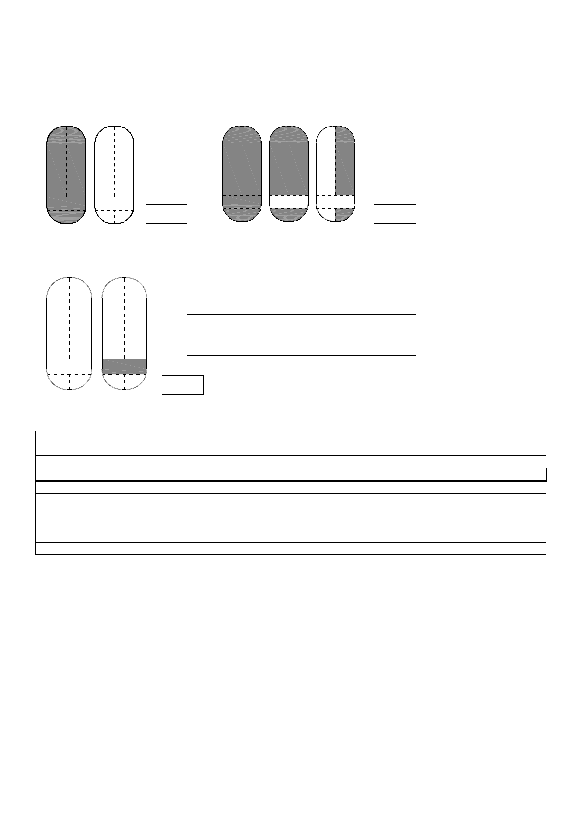
HOW TO PROCEED TO CHECK the 24 hours lines and the lines balancing:
The LED LD1 visualizes the tamper open according to the priority shown in the chart “LED Tamper” so, if the LED flashes 5 times, it
means that the only opened tamper is the one on the bottom of the sounder or the cover so the zones are correctly balanced and
the 24 hours line is closed.
USE
The following behaviours have to be taken into consideration:
If a line goes in alarm, in order for it to be able to trigger off a new one at the end of the alarm cycle, it must re-balance
(condition of non-alarm) and unbalance again.
This behaviour is valid for normal alarms, for the 24 hours line and for the Reed tamper.
A delayed line still unbalanced at the end of the output time causes an alarm without waiting for the input time.
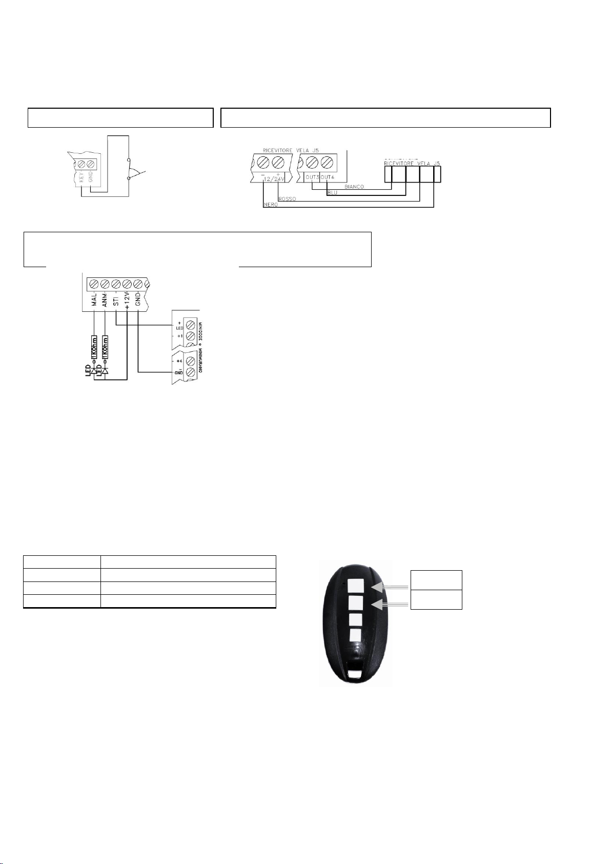
ARMING
Putting the key in position ON or pressing the pushbutton A (total) or B (partial) of the remote control, the anti-intrusion zones
activate, the zone 1 will become operative after the output time. At the same time, the indication of armed system (three flashes) or
of output time (flashes during the whole output time) switches on.
The output STI (system status) activates fix at 0V in case of total arming or intermitting in case of partial arming.
INPUT/OUTPUT TIME
After arming the control panel, the output time starts, at the same time the indication of armed system switches on and the zones 2
and 3 are operative.
Once this time is finished, the zone 1 becomes operative. At armed system, the opening of an immediate zone causes the general
alarm whilst the opening of a delayed zone activates the general alarm after the input time if the system is not disarmed meanwhile.
The duration of the input and output time is set by DIP3.
DISARMING
Putting the mechanical key in OFF position or pressing the pushbutton A or B of the remote control, the anti-intrusion lines de-
activate and the indication of active system switches off.
PARTIAL ARMING
Further to the total arming (all lines active), the control panel can also be armed in partial mode PART, with line 3 not active. This
type of arming allows to maintain protected some zones and to move freely in the zone 3.
In order to arm the system in partial mode, press the pushbutton B of the remote control, the lamp will flash to show arming. The
Led of system status lights up flashing to show partial arming.
Behaviour:
1) System armed: active system-status output. The Led of the lamp flash three times.
a) Zones 1, 2, 3 or tamper in alarm: active alarm output. Sound of the sounder for the time-lapse of DIP 1. Flashing of the Led
for infinitive time showing the first zone in alarm. The number of flashes shows the zone in alarm. If all Led flash
progressively it’s a 24 hours alarm.
b) System disarming by key or remote control, LED switching off
2) Arming with zone 1 open: if the zone is set as delayed, the lamp will flash quickly during the output time
3) Anomalies such as: Zone 1 open, low battery, mains absence, problems on battery or horn make the lamp flash quickly in any
status of the system.
4) Max number of alarms per zone: when the DIP is set on OFF, any zone causes max 4 alarms in 24 hours. Once expired the 24
hours from first alarm, zones are re-enabled to trigger off alarme. Even in case of disarming and the arming, the lines are re-
enables and the alarm counting starts again. The 24 hours has no limit in alarms number.

MA-SE-DCT3-01-02 Manual Doge CT3 eng rev2 Rev.4 Pagina 9 di 17
5) Alarm memory: at the end of the alarm time-lapse, the lamp will show the first zone giving alarm by a certain number of flashes;
at disarming all visualizations are cancelled by DIP7, on the other hand the alarm memory is cancelled at rearming of the system
by DIP7 OFF. Disarmed system: disarmed system output , status Led: long flash .
6) System disarmed: system output deactivated. Led status: long flash
7) Missing mains: after 3 hours of mains missing, the terminal for missing mains activates and the anomaly Led emits 2 flashes.
8) Low battery: when the battery goes under 9,7V and the mains is missing, the control panel stops working until battery returns
to a tension over 9,,in order to safeguard it. The external Leds and the internal Led of anomaly, alarm and alarm memory
remain active.
9) Battery totally low (reset of the sounder): because of a long mains missing the battery goes under 6,9 Volt and the sounder as
well as the indications totally switch off. When the mains return the controls panel returns to the status shown by the
mechanical key, so in case you wish a total arming condition after a long mains missing, leave the key terminal not connected; If
on the other hand, you wish the disarmed condition, connect the same terminal to the ground. In order to avoid false alarms
during installation a possible open line will not cause an alarm until its closing and re-opening. Furthermore it is necessary to
command 3 arming/disarming operations via the remote control, in order to disarm the system.
ANOMALIES:
Flash: it shows anomalies in real time, in case of anomaly, during arming and disarming operations it will flash quickly. As soon as
the anomaly disappear, flash returns to normal speed (about 1 flash per second).
LED Anomalies on board: it shows anomalies immediately included mains missing and visualizes the highest-priority anomaly. If
there are several anomalies it is necessary to solve out the one visualized,in order to see the others. Memory is cancelled by
disarming and re-arming the system. The number of flashes shows the anomaly as per the chart LED Anomalies.
Output terminal: It activates the open collector output in order to indicate anomalies in real time and keeps them in memory until
following arming; mains missing is shown after 3 hours in order not to start unnecessary indications.
Internal resistance and not connected battery:
The control of the internal resistance is made 30 seconds after the sounder supplying. Then, every 2 hours. In case of battery
replacement, if you wish to start the test of the internal resistance, disconnect the battery and the control panel recharge for 10
seconds.
TAMPER:
Tamper, 24h zone and not-balanced zones
A tamper alarm can be caused by: 24h zone open, cover tampering or removal tampering, or zones short-circuit if set as balanced .
The alarm is active at both armed and disarmed system.
The alarm causes a “rotating” flashing of the sounder and internally the LED LD1 flashes so as to detect which tamper has caused the
alarm. If there are more alarms, the Tamper LED shows the high-priority one.
The zone in tamper alarm is shown as in the chart Tamper LED.
CONNECTORS:
J1: power supply + 13,8V, 0V Recharge
J2: flash and anti-drilling
J3: battery and horn
J4: do not connect
J5: Vela receiver
J6: Anti-foam
J5, VELA receiver
Cable
Signal
Connection to VELA
Black
Ground
-(12/24)
Red
+12V
+ (12/24)
White
Total
OUT 3
Blue
Partition
OUT 4

MA-SE-DCT3-01-02 Manual Doge CT3 eng rev2 Rev.4 Pagina 10 di 17
TECHNICAL FEATURES
Supplying
13,8Vdc (min13Vdc, MAX 15Vdc)
[KIT : 230Vac (+15/-10%) 50Hz]
Electrical isolation
II
Maximum consumption from mains
75mA
Recharge tension
13,0 13,8 V
Minimum tension of working
10 V
Maximum tension of working
15 V
Batteries
12 V –1,2 Ah or 2,2 Ah
Current supply from supply unit
500mA
Current available for additional devices
350mA
Internal consumption –at control panel disarmed
30mA
- at control panel armed
40mA
- at control panel armed with status visualization
70 mA
- at control panel in alarm
1,2A 100 mA (consumption of the battery )
Flash consumption in alarm
90 10 mA (consumption of the battery)
Autonomy (without continuous visualization)
50 hours with 12V 2,2 Ah battery
Balance resistance (single)
5k6 Ohm
Output of system status STI, Push Pull
+50mA / -100mA Max
Output alarm memory and anomaly, Open Collector
-100mA Max
Timer of switching off of the siren and alarm relay
3 minutes, can be set to 8 minutes
Frequency limits
See chart 12 (Sounds)
Acoustic power
See chart 12 (Sounds)
Duration of the Led flash
1.000.000 flash minimum
Conditions of humidity
from 20% to 100% of humidity
Material
Bottom in ABS
External cover in painted ABS and charged against UV
Internal cover in steel 1,2mm
Size
mm 155x100x53 (HxLxD)
Weight
2500 g
Operating temperature
IP protection
Tamper protection
From - 20 °C a +55 °C
IP 3X
Opening of the cover and removal from the wall, anti-
foam and (optional) anti-drilling
Mounting and Installation:
The sounder must be installed inside buildings by qualified personnel and taking into consideration all norms related to installation,
respecting distances and heights in order to obtain the best acoustic and visual efficiency.
Fix the sounder to the wall, through the 4 holes on the bottom of the housing (see picture 9). The screws are not given within.
For connecting the cables use a joint in case of system with external pipes.
If necessary modify the setting of the dip-switches.
Connect the terminals to the control panel according to the pictures scheme.
Close the cover using the screw given.
Pict. 9
-
FIXING HOLES

MA-SE-DCT3-01-02 Manual Doge CT3 eng rev2 Rev.4 Pagina 11 di 17
INSTALLATION GUIDE with all DIP SWITCHES in OFF POSITION
YES
YES
YES
YES
NO
NO
Use the dedicated cable to connect the remote control receiver,
then set keys A and B (Pict. 7 and Guide to VELA remote control
setting)
Connect zones 1, 2 and 3 to the detectors (Pictures from 2 to 5)
Connect the 24h line in series with the tamper of all devices
Connect the battery to the dedicated FASTONS and the power
supply to power supply connector J1
Push A button of the remote control several times, until the front
LEDs start flashing
Is the anomalies LED off?
Do the front LEDs flash for 1 minute?
Does the tamper LED
make 5 flashes?
Put zone 2 in alarm status
Do the front LEDs make 2 flashes and then a pause
AND does the loudspeaker sound at low volume?
Push A button of the remote control twice
Front LEDs flash for 1 minute
If the 24h line
and the zones
are not used,
connect them to
the ground
Tamper LED
turns on steady
NOTE: the KIT
does not require
it since it is
already set
NOTE: in case of
KIT, just check the
connection to AC
(230V)
Solve the anomalies. See
chart 3
The control panel is
armed, in OUTPUT
and in Walk Test
The cover is open,
which is the only
tamper noticed
Tamper LED makes 4 flashes
Check zones
connection
Push A button of the
remote control twice
NO
NO
The control panel
has been disarmed
and armed again
in Walk Test mode
See the scheme here below for the final
test

MA-SE-DCT3-01-02 Manual Doge CT3 eng rev2 Rev.4 Pagina 12 di 17
WHAT TO DO IN CASE:
THE LOUDSPEAKER SOUNDS AT LOW VOLUME: CHECK THE TAMPER DEVICES, in case the anti-drilling film is not present, the
connector on the flash must have a jumper. The cover must be able to close without forcing it. Count the flashes as indicated in
chart 2.
THE FLASHING UNIT FLASHES IN STRANGE WAY, “ON A ROTATING BASIS”: IT IS A TAMPER ALARM 1) verify the 24h line: it must be
undamaged and closed in connection to the ground; 2) open the sounder cover and count the number of “ZONE TAMPER” flashes,
in case they are 5, locate a jumper on the anti-drilling connector, close the cover and arm the control panel. There must be no
alarms and the sounder must not sound at low volume.
If an alarm keeps being present, locate a jumper on the anti-foam connector, close the cover and check if the sounder works
properly.
THE FLASHING UNIT FLASHES FAST: THERE IS AN ANOMALY. Check if the sounder is correctly powered through the power supply
connector. Open the sounder cover and count the number of flashes as indicated in chart 3. Solve the anomaly, then turn the
sounder off and then on again. Check if the anomaly is solved and close the sounder cover.
THE SOUNDER DOES NOT SOUND BUT IT FLASHES: THE BATTERY IS DISCHARGED. Open the cover and count the number of flashes
as indicated in chart 3. Disconnect the power supply connector (J1) and replace the battery. Connect J1 and the battery, wait a
minute, then arm and disarm the control panel, verify whether there are any anomalies and close the cover.
NO
YES
Put the other zones in alarm
status
Disarm the system
Close the cover
Push A button of the
remote control once
Put one zone in alarm
status (e.g. zone 2)
Does the loudspeaker
sound at 110dB?
Push A button of the
remote control once
END
ATTENTION: zone 1
is delayed; wait 30
seconds before the
alarm is launched
The control panel is
armed
The control panel is
disarmed
Push A button of the
remote control once
Check all tamper
devices: cover, anti-
foam and anti-drilling
Push A button of the
remote control once

MA-SE-DCT3-01-02 Manual Doge CT3 eng rev2 Rev.4 Pagina 13 di 17
GUIDE TO VELA REMOTE CONTROL SETTING
NO
NO
YES
YES
TESTING
Push A button of the remote
control
Does LED 2 make a GREEN flash?
Push B button of the remote control
Does LED 2 of the remote
control make a RED flash?
END
Set the receiver once
again: SEE VELA REMOTE
CONTROL MANUAL
NO
YES
NO
YES
YES
YES
YES
NO
Connect the remote control receiver
to DOGE CT3 using the dedicated
cable (Picture 7)
Give power supply to DOGE CT3,
using a battery or a power supply
unit
Do the 2 LEDs of the receiver make
a GREEN flash?
Push the button of the receiver three
times
Is LED 2 of GREEN colour?
Push A button of the remote control
Does LED 2 make a flash?
Push the remote control
button four times
Is LED 2 of RED colour?
Push B button of the remote control
Push once the button of the receiver
Are the receiver
LEDs turned off?
Check
the
connecti
ons
Push the
remote
control
button
once
more
PASS TO TESTING
Push the
remote
control
button
once
more
NO

MA-SE-DCT3-01-02 Manual Doge CT3 eng rev2 Rev.4 Pagina 14 di 17
VELA
RADIO-TRANSMITTER AND RECEIVER
433.92MHz ASK-Rolling Code
DESCRIPTION:
Vela is an ergonomic and versatile radio-transmitter. It is provided with 4 push-buttons and one LED that goes on during code transmission.
Superheterodyne receiver with ASK modulation, 4 channels with 2 relays and 2 open collector output, high performances and reliability. It has decode
function, auto-acquiring of transmitter, anti-aliasing digital filter for optimized radio-performances. The dedicated firmware is extremely flexible and
intuitive. It grants advanced functions as change of working modality for each channel.
It has a SAW filter for optimizing the selectivity and suppress out of bandwidth noise. It is even equipped with a reliable power supply with anti-noise
filters and line protection against overvoltage.
FEATURES
European I-ETS 300 220 and ETS 300 683 Approved
APPLICATIONS:
Radio transmitter for sirens, burglar alarms, remote light switching, gates, up-and-over doors etc.
1 –Wired Antenna shield
2–Input antenna
3 –negative terminal
4 –positive power supply
5 –relay 1 contact n.o.
(Led 1 green when activated)
6–relay 1 contact common
7 –relay 2 contact n.o.
(Led 1 red when activated)
8–relay 2 contact common
9 –output 3 Open Collector
(Led 2 green when activated)
10 –output 4 Open Collector
(Led 2 red when activated)
ELETTRICAL FEATURES OF RECEIVER AT +25 °C
Parameter
Min.
Typ.
Max.
Unit
Notes
Power supply (VDC)
12
-
30
Volt
Power supply (VAC)
12
-
28
Volt
Absorption (receiver only)
-
14
-
mA
Absorption (1 relay active)
-
45
-
mA
Absorption (2 relays active)
-
70
-
mA
Absorption (4 outputs active)
-
80
-
mA
Center band frequency
-
433.92
-
MHz
Sensitivity
-
-105
-
dBm
Note 1
Bandwidth RF –3dB
-
±100
-
kHz
Irradiated clutters on antenna
-
-
-60
dBm
Power up time
-
-
2,8
s
Note 2
Command activation time
-
-
0,5
s
Note 3
Max. capacity of output contacts VDC
-
-
1A 24V
Amp Vdc
Max. capacity of output contacts VAC
-
-
1A 48V
Amp Vac
Max. capacity Open Collector output
-
-
10mA
mA
Note 4
Working temperature
-20
+25
+70
°C
Note 1: Measured with AM signal 100% square wave, 1KHz frequency.
Nota 2: Lead time from switching on and reception of a valid code
Nota 3: Lead time from command transmission (button pressure) and output activation
Nota 4: Max applicable voltage depends on power supply of receiver 24V o 30V
Nota 5: All measures relevant to RF parameters are done with terminal 2 connected to an antenna of 50 Ohm impedance.
MECHANICAL FEATURES AND SCREW TERMINAL
External dimension:
H (height)
16,0 mm
W (width)
40,5 mm
L (lenght)
36,5 mm
BUTTON
LED 2
LED 1

MA-SE-DCT3-01-02 Manual Doge CT3 eng rev2 Rev.4 Pagina 15 di 17
ELETTRICAL FEATURES OF TRANSMITTER AT +25 °C
Parameter
Number of buttons
4
Power supply
3V
3V Lytium battery (type
CR2032)
Absorption (during transmission)
8mA
Antenna
1
integrated
Oscillator type
SAW
Working temp.
from -10°C to
+55°C
Center Band frequency
433.92 MHz
APPLICATION NOTES
–RELAY OUTPUT CHANGE
To modify relay outputs from normally open (N.O.) to normally closed (N.C.)
Cut the route relevant to desired output as in below figure
N.B. After cutting the route remember to solder the indicated pads with a drop of tin!
–ANTENNA
For increasing the range of board connect a 17cm isolated wire of 1mm to terminal 2 (input of antenna). The best placement is
obtained by fixing the wire to the terminal and disposing it perpendicularly from board, on the same plane.

MA-SE-DCT3-01-02 Manual Doge CT3 eng rev2 Rev.4 Pagina 16 di 17
USER MANUAL
RECEIVER PROGRAMMING AND OUTPUT CONFIGURATION
All programming operations of receiver and outputs configuration are made by the same button.
The two bicolor LEDs (green, red, red-green) give the information on different programming and configuration phases.
LED 1 is located at the left side of LED 2 ; each LED gives the indications on output state:
LED 1 green: carried out operations refer to terminal RL1;
LED 1 red: carried out operations refer to terminal RL2;
LED 2 green: carried out operations refer to terminal OUT3;
LED 2 red: carried out operations refer to terminal OUT4;
ACQUISITION AND REMOVAL
By the acquisition procedure the transmitters that actualize the output of receiver are memorized
By the removal procedure the desired transmitter or all transmitters are removed from memory of receiver.
To start the acquisition and removal mode.
For switching from an option to another push and release the button.
1st push: LED 1 is green. Acquiring phase of a transmitter on RL1;
2nd push: LED 1 is red. Acquiring phase of a transmitter on RL2;
3rd push: LED 2 is green. Acquiring phase of a transmitter on OUT3;
4th push: LED 2 is red. Acquiring phase of a transmitter on OUT4;
5th push: LED 1 blinks with red-green color. Removal phase of a transmitter from memory.
When the button is released the receiver remains in the selected option for 5 seconds. After they have expired, the receiver exits
the selected mode; if during these 5 seconds it receives a valid code, a signal of correct memorization or removal is given by
LEDs switching-off for 0,5 seconds.
When a transmitter is memorized or removed, 5 more seconds are available for a further memorization or removal.
Exemple 1: memorization of transmitter on relay 1:
Push and release the button: LED 1 turns on green;
within 5 seconds generate a signal for memorizing the desired transmitter;
LED turns off for 0,5 seconds to confirm the acquisition;
Wait for 5 seconds (or push again the button and release it) so that the receiver exits from acquiring mode: the return to
operating mode is signaled by LED switching-off.
Exemple 2: memorization of transmitter on OUT4:
Push the button 4 times: at first pressure LED 1 switches on green, at second pressure LED 1 switches on red, at third
LED 2 switches on green, at fourth LED 2 switches on red;
LED turns off for 0,5 seconds to confirm the acquisition;
Wait for 5 seconds (or push again the button and release it) so that the receiver exits from acquiring mode: the return to
operating mode is signaled by LED switching-off.
Exemple 3: removal of transmitter from memory:
Push the button 5 times: at first pressure LED 1 switches on green, at second pressure LED 1 switches on red, at third
LED 2 switches on green, at fourth LED 2 switches on red; at fifth pressure LED 1 blinks in red-green.
within 5 seconds generate a signal for remove the desired transmitter;
LED turns off for 0,5 seconds to confirm the removal (if transmitter wasn’t previously acquired, removal is not signaled);
Wait for 5 seconds (or push again the button and release it) so that the receiver exits from acquiring mode: the return to
operating mode is signaled by LED switching-off.
SETTING OF OUTPUTS
All outputs can be settled on following modes
MONOSTABLE mode: at reception of code the output stays active during reception of it;
BISTABLE mode: at reception of code the output activates if previously it was deactivated and vice versa;
TEMPORIZED mode: at reception of code the output activates for a presetted time. Note: for deactivating the output,
push again the button of transmitter after at least 5 seconds from activation.
Selecting a working mode
To enter the setting mode of outputs it is necessary to keep pushed the button during acquiring phase until the LED of chosen
output for mode change, start to blink.
Exemples:
Setting of relay 1: push and keep pushing the button. LED 1 switches on green. After 3 seconds from pressure of
button, LED 1 green starts to blink quickly: setting mode MONOSTABLE.
Setting of OUT3: push and release the button. LED 1 switches on green. Push the button a second time and release it:
LED 1 switches on red. Push the button a third time and keep pushing: LED 2 switches on green. After 3 seconds from pressure
of button, LED 2 green starts to blink quickly to signal MONOSTABLE mode.
After 5 seconds without pushing the button LED blinks slowly to signal MONOSTABILE mode.
If the button is pushed during quick blinking, BISTABILE mode is selected and signaled by 2 quick blinks continuously executed.
After 5 seconds without pushing the button LED blinks twice slowly to signal BISTABLE mode.
By another pressure on button during quick blinks TEMPORIZED mode is selected: LED blinks 3 times quickly. After 5 seconds
without pressure LED 1 switches on red-green (for channels 1 and 2) or LED 2 red-green (for channels 3 and 4). After 3 seconds
without pushing the button LED red-green, TEMPORIZED mode is confirmed and activation time of outputs is 5 seconds.
If the button is pushed for 0,5 seconds during switching on of red-green LED, the pressure of button is signaled by the switching
on of LED relevant to the output to be settled. At each pressure of button the activation time is increased as follows:

MA-SE-DCT3-01-02 Manual Doge CT3 eng rev2 Rev.4 Pagina 17 di 17
No. of pressures
0
1
2
3
4
5
6
7
8
9
10
11
Time settled
5 s
15 s
30 s
45 s
1 min
2 min
3 min
4
min
5 min
10 min
15 min
20 min
Temporized Output
For example, for obtaining an activation time of 30 seconds it is necessary to push the button twice.
Then, after 3 seconds without pressure of button, the receiver exits from TEMPORIZED setting mode.
At exit from the mode, the number of pressures is visualized by the same number of changes of LED from red-green color to the
color relevant to the settled output.
Maximum number of settable time is 20 minutes which is 11 pressures of button.
Exit from setting mode of output
If button is pushed during the three quick blinks which indicate TEMPORIZED mode, the receiver goes back to normal working
state without any change on behavior of output
Memory removal
For removing all transmitters from memory, at the fifth pressure (removal phase) keep pushing the button for 3 seconds during
red-green blinking until red-green LED switches on steadily. Then you can release the button.
When red-green LED switches off the memory has been deleted and all outputs are settled on MONOSTABLE mode.
For removing only one transmitter: at the 5th pressure, push the button of transmitter that you want remove.
NOTE:
Maximum number of acquirable transmitters: 50
Activation of output
Activation of outputs is signalled by switching on of relevant LED: LED1 is green indicates activation of output relay 1; LED1 red
indicates activation of output relay 1; LED1 red and green indicates that both outputs are activated.
The same happens for outputs 3 and 4. LED2 is green indicates activation of output relay 3; LED2 red indicates activation of
output relay 4; LED2 red and green indicates that both outputs are activated.
If the range of transmitter decreases considerably, the battery is probably discharged: change the battery.
N.B.
Danger of explosion if replaced battery is not of approved type. For battery disposal, please follows the guidelines of your country.
Venitem declares that this transmitter and receiver conform to the standards and regulations relevant to Directive 1999/5/CE.
Conformity Declarations can be consulted on website www.venitem.com. All necessary radiofrequency test were performed.
Warranty: All Venitem products are granted for 24 months.
With the aim of improving the design and the quality of the products, the company Venitem reserves the right of modifying the
product without previous notice. All faulty pieces must be returned to the Supplier.
Via del Lavoro, 10 - 30030 Salzano (VE) Tel. (+39) 041 5740374 –Fax (+39) 041 5740388 Web site www.venitem.com E-mail info@venitem.com
Table of contents
Other Venitem Security System manuals