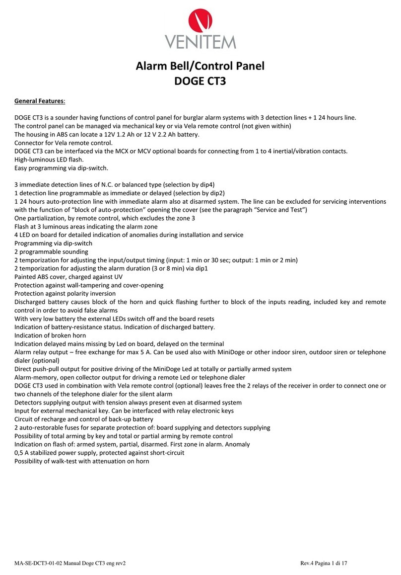
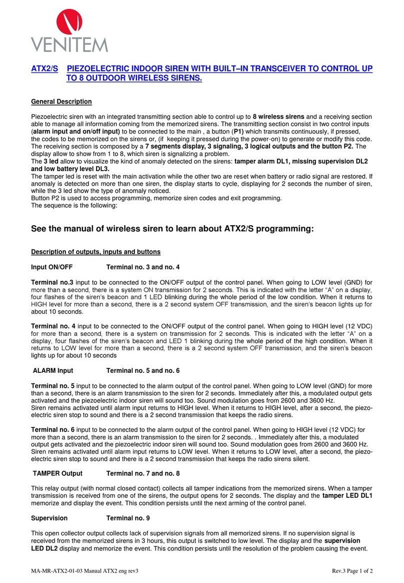
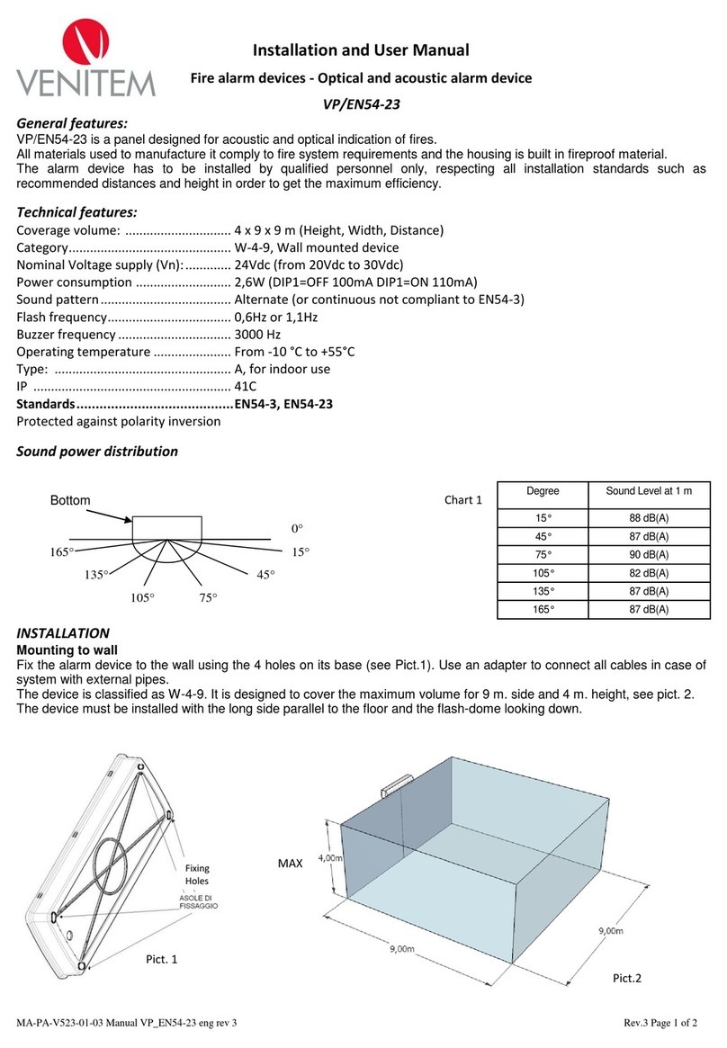
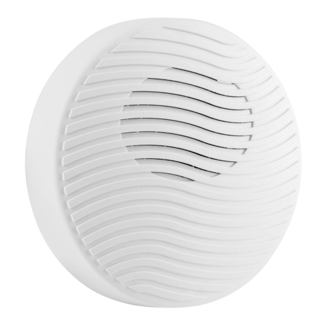
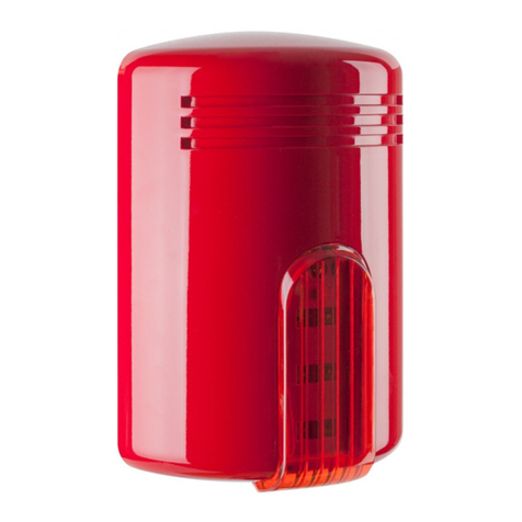
Venitem RIO Series User manual

MANUALE TECNICO
TECHNICAL MANUAL
L-LS
RIO—RONDÒ
Nothing is left to chance
Nulla è lasciato al caso
venitem.com

2
Descrizione sirena mod. Rio/Rondò L: sirena autoalimentata 12 Vdc con lampeggiante a led ad alta luminosità
e basso assorbimento - tamper antiapertura e rimozione - autocontrollo a microprocessore di: batterie e speaker*
- programmazione suono e temporizzazione - segnalazione ottica ON-OFF impianto istantanea e permanente -
circuito elettronico protetto da inversioni di polarità.
Descrizione sirena mod. Rio/Rondò LS: Caratteristiche tecniche come Rio/Rondò L con sistema antischiuma
antischock a doppio micro contro gli urti violenti.
La base della sirena è dotata di un gancio al quale è possibile appendere sia il coperchio interno che quello
esterno durante le operazioni di installazione e manutenzione.
* La funzione autocontrollo a microprocessore di batterie e speaker è presente solo nella sirena Rio
ITA
A - COLLEGAMENTO A DUE CONDUTTORI.
Collegare l’alimentazione 13,8 Vdc proveniente dalla centrale ai rispettivi morsetti:
n°1 negativo; n°2 positivo. (il comando n° 3 va ponticellato al positivo n° 2)
N.B. lasciare il dip-switch n°3 in off (positivo a mancare)
B - COLLEGAMENTO A TRE CONDUTTORI.
Collegare l’alimentazione 13,8 Vdc proveniente dalla centrale ai rispettivi morsetti:
n°1 negativo; n°2 positivo; n°3 comando positivo a mancare .
N.B. da fabbrica dip-switch n°3 in off (positivo a mancare)
C - SEGNALAZIONE OTTICA DI STATO IMPIANTO (on-off istantaneo e permanente).
• Portando un positivo al morsetto n°4 tutti i led del lampeggiante eseguono 3 lampeggi (ON);
• Togliendo il positivo tutti i led rimangono accesi fissi per 5 secondi (OFF).
Dip-switch 4 in OFF DA FABBRICA (Situazione istantanea di ON-OFF)
Dip-switch 4 in ON (Situazione istantanea di ON-OFF con permanenza di un led intermittente per il tempo in cui
c’è tensione positiva al morsetto n°4).
D - TEMPORIZZAZIONE SIRENA.
Da fabbrica la temporizzazione è di 4 minuti (DIP-SWITCH 1 OFF) e può essere modificata a 8 minuti
(vedi tabella temporizzazione sirena).
E – MORSETTO N°6 INGRESSO POSITIVO DI BLOCCO SUONATA (OPTIONAL FORNITO SOLO SU RICHIESTA)
Attiva il relé di interruzione suono portando un segnale positivo al morsetto n°6.
F - LED USCITA ANOMALIA (Solo per sirena Rio).
La sirena Rio è gestita da un microprocessore in grado di controllare la batteria e lo speaker; in caso di anomalia
invia un segnale negativo open-collector al morsetto OUT LED e il led presente nel circuito sirena indica il tipo di
guasto a seconda del numero di lampeggi seguiti da una breve pausa.
Il microprocessore esegue automaticamente ogni 32 giorni il test di corrente batteria e in caso di non
superamento attiverà l’uscita OUT LED e il led di anomalia eseguirà 3 lampeggi seguiti da una breve pausa.
Inoltre il microprocessore stesso si autocontrolla in ogni istante e nel caso di guasto o mal funzionamento blocca
il suono.
SCHEMA DI COLLEGAMENTO
TABELLA DI SEGNALAZIONE ANOMALIE LED ROSSO ANOMALIA
IMPIANTO ACCESO/
SPENTO
INTERRUZIONE SPEAKER A RIPOSO 6 IMPULSI NEGATIVI
DRIVER SIRENA DANNEGGIATI 4 IMPULSI NEGATIVI
BATTERIA GUASTA (test che si effettua ogni 32 giorni) 3 IMPULSI NEGATIVI
BATTERIA INSUFFICIENTE 2 IMPULSI NEGATIVI
BATTERIA INSUFFICIENTE (test sempre presente con soglia di
riferimento sotto i 9V)
1 IMPULSO NEGATIVO
G - COLLEGAMENTO TAMPER ANTISTRAPPO E RIMOZIONE COPERCHIO
Collegare la linea tamper proveniente dalla centrale in serie ai due fili del microswitch presente sulla sirena
utilizzando i morsetti di supporto n° 8 e n° 9.
H- COLLEGAMENTO ANTISCHIUMA (per modelli LS)
Collegare in serie alla linea Tamper centrale e al microswitch i due fili della griglia antischiuma.
Le segnalazioni di anomalie riportate nella tabella rimangono in memoria finchè non si presentano
i seguenti casi:
1) mancanza del comando (mancanza del positivo/negativo al morsetto n°3);
2) accensione dell’impianto (invio +12 Vdc al morsetto n°4);
Esempio collegamento a tre conduttori
CONSIGLI PER L’INSTALLAZIONE:
Nel caso di funzionamento anomalo della sirena verificare se il Led presente sulla scheda lampeggi.
Se lampeggia controllare la tabella di segnalazioni anomalie (solo su sirena Rio).
Nel caso di utilizzo del comando di ON/OFF anche per altri apparecchi collegare sul morsetto 4 un diodo 1N4007.
SCHEMA ELETTRICO DI COLLEGAMENTO
COM Alimentazione negativa
+RIC Alimentazione positiva +13,8 Vdc
+C Ingresso comando a mancare
LED Ingresso ON-OFF
BLOC Ingresso blocco suonata (optional)
TAMPER Morsetto di supporto per tamper
OUT LED Uscita negativa di anomalia
(Solo su sirena Rio)

3
Descrizione sirena mod. Rio/Rondò L: sirena autoalimentata 12 Vdc con lampeggiante a led ad alta luminosità
e basso assorbimento - tamper antiapertura e rimozione - autocontrollo a microprocessore di: batterie e speaker*
- programmazione suono e temporizzazione - segnalazione ottica ON-OFF impianto istantanea e permanente -
circuito elettronico protetto da inversioni di polarità.
Descrizione sirena mod. Rio/Rondò LS: Caratteristiche tecniche come Rio/Rondò L con sistema antischiuma
antischock a doppio micro contro gli urti violenti.
La base della sirena è dotata di un gancio al quale è possibile appendere sia il coperchio interno che quello
esterno durante le operazioni di installazione e manutenzione.
ITA
A - COLLEGAMENTO A DUE CONDUTTORI.
Collegare l’alimentazione 13,8 Vdc proveniente dalla centrale ai rispettivi morsetti:
n°1 negativo; n°2 positivo. (il comando n° 3 va ponticellato al positivo n° 2)
N.B. lasciare il dip-switch n°3 in off (positivo a mancare)
B - COLLEGAMENTO A TRE CONDUTTORI.
Collegare l’alimentazione 13,8 Vdc proveniente dalla centrale ai rispettivi morsetti:
n°1 negativo; n°2 positivo; n°3 comando positivo a mancare .
N.B. da fabbrica dip-switch n°3 in off (positivo a mancare)
C - SEGNALAZIONE OTTICA DI STATO IMPIANTO (on-off istantaneo e permanente).
• Portando un positivo al morsetto n°4 tutti i led del lampeggiante eseguono 3 lampeggi (ON);
• Togliendo il positivo tutti i led rimangono accesi fissi per 5 secondi (OFF).
Dip-switch 4 in OFF DA FABBRICA (Situazione istantanea di ON-OFF)
Dip-switch 4 in ON (Situazione istantanea di ON-OFF con permanenza di un led intermittente per il tempo in cui
c’è tensione positiva al morsetto n°4).
D - TEMPORIZZAZIONE SIRENA.
Da fabbrica la temporizzazione è di 4 minuti (DIP-SWITCH 1 OFF) e può essere modificata a 8 minuti
(vedi tabella temporizzazione sirena).
E – MORSETTO N°6 INGRESSO POSITIVO DI BLOCCO SUONATA (OPTIONAL FORNITO SOLO SU RICHIESTA)
Attiva il relé di interruzione suono portando un segnale positivo al morsetto n°6.
F - LED USCITA ANOMALIA (Solo per sirena Rio).
La sirena Rio è gestita da un microprocessore in grado di controllare la batteria e lo speaker; in caso di anomalia
invia un segnale negativo open-collector al morsetto OUT LED e il led presente nel circuito sirena indica il tipo di
guasto a seconda del numero di lampeggi seguiti da una breve pausa.
Il microprocessore esegue automaticamente ogni 32 giorni il test di corrente batteria e in caso di non
superamento attiverà l’uscita OUT LED e il led di anomalia eseguirà 3 lampeggi seguiti da una breve pausa.
Inoltre il microprocessore stesso si autocontrolla in ogni istante e nel caso di guasto o mal funzionamento blocca
il suono.
G - COLLEGAMENTO TAMPER ANTISTRAPPO E RIMOZIONE COPERCHIO
Collegare la linea tamper proveniente dalla centrale in serie ai due fili del microswitch presente sulla sirena
utilizzando i morsetti di supporto n° 8 e n° 9.
H- COLLEGAMENTO ANTISCHIUMA (per modelli LS)
Collegare in serie alla linea Tamper centrale e al microswitch i due fili della griglia antischiuma.
Le segnalazioni di anomalie riportate nella tabella rimangono in memoria finchè non si presentano
i seguenti casi:
1) mancanza del comando (mancanza del positivo/negativo al morsetto n°3);
2) accensione dell’impianto (invio +12 Vdc al morsetto n°4);
Negativo ricarica
CENTRALE
Fili Microswitch
Linea tamper centrale
Comando positivo a mancare
Positivo ricarica
Esempio collegamento a tre conduttori
CONSIGLI PER L’INSTALLAZIONE:
Nel caso di funzionamento anomalo della sirena verificare se il Led presente sulla scheda lampeggi.
Se lampeggia controllare la tabella di segnalazioni anomalie (solo su sirena Rio).
Nel caso di utilizzo del comando di ON/OFF anche per altri apparecchi collegare sul morsetto 4 un diodo 1N4007.
SCHEMA ELETTRICO DI COLLEGAMENTO
COM Alimentazione negativa
+RIC Alimentazione positiva +13,8 Vdc
+C Ingresso comando a mancare
LED Ingresso ON-OFF
BLOC Ingresso blocco suonata (optional)
TAMPER Morsetto di supporto per tamper
OUT LED Uscita negativa di anomalia
(Solo su sirena Rio)
ON
OFF

4
NB: Per evitare la formazione di condensa nella sirena si deve impedire qualsiasi flusso d’aria
nella canalina, tubo corrugato o foro di passaggio cavi. Una volta passati i cavi sigillare il foro
con del silicone o un altro stucco. Questa operazione evita che, durante il periodo invernale, l’aria
calda e umida che esce dall’edificio attraverso il passaggio vada a formare condensa nella sirena
precludendo il corretto funzionamento di questa.
Tensione
Nominale di Alimentazione
Comando minimo
Alimentazione minima
Alimentazione massima
13,8 Vdc
4,5 Vdc
10.5 Vdc
15.5 Vdc
Corrente
Assorbimento suono
Assorbimento lampeggiante
Attesa
1,5 A
60mA
15 mA
Frequenza fondamentale U1704Hz
Pressione sonora U105 dB (A) 3 mt.
Grado di protezione UIP 44
Condizioni ambientali esterne UDa -25° a +55° C
Temporizzazione UProgrammabile
Capacità della batteria U12V 1,2Ah o 12V 2.2 Ah
massimo
Comando della centrale U2 o 3 fili
Dimensioni U330x220x110 mm (H x L x P)
Peso U1850gr
CARATTERISTICHE TECNICHE RIO/RONDÒ
CERTIFICAZIONI
RIO L: Sirena con coperchio in plastica ABS verniciato
Conforme EN 50131-4
RIO LS: Sirena con coperchio in plastica ABS verniciato provvista di sistema antischiuma.
Conforme EN 50131-4
RONDÒ L: Sirena con coperchio in plastica ABS verniciato
Sistemi di sicurezza II livello.
Conforme EN 50131-4
RONDÒ LS: Sirena con coperchio in plastica ABS verniciato provvista di sistema antischiuma.
Sistemi di sicurezza II livello.
Conforme EN 50131-4
GARANZIA
Tutti i prodotti Venitem sono garantiti contro i difetti di fabbricazione o di materiale. Nell’intento di migliorare il
design e la qualità dei propri prodotti la ditta Venitem si riserva di modificare il prodotto senza alcun preavviso.
Tutti i prodotti guasti o difettosi vanno resi al proprio fornitore.
SETTAGGIO DIP-SWITCH
2 - SELEZIONE COMANDO
DIP 2
OFF POSITIVO A MANCARE
(da fabbrica)
ON NEGATIVO A MANCARE
4 - SELEZIONE LED STATO IMPIANTO
DIP 4
OFF NON ATTIVA 1 LED DI
PERMANENZA STATO
IMPIANTO (da fabbrica)
ON ATTIVA 1 LED DI
PERMANENZA STATO
IMPIANTO
3 - SELEZIONE SUONI
DIP 3
OFF SUONO ITALIANO 1432HZ FREQUENZA FONDAMENTALE
(da fabbrica)
F:MIN F:MAX
ON SUONO FRANCESE 1400HZ 1600HZ
(perdita certificazione IMQ su
sirena Rondò)
ITA
DIP 1
OFF 4 MINUTI (da fabbrica)
ON 8 MINUTI
1- TEMPORIZZAZIONE SIRENA

5
ITA
NB: Per evitare la formazione di condensa nella sirena si deve impedire qualsiasi flusso d’aria
nella canalina, tubo corrugato o foro di passaggio cavi. Una volta passati i cavi sigillare il foro
con del silicone o un altro stucco. Questa operazione evita che, durante il periodo invernale, l’aria
calda e umida che esce dall’edificio attraverso il passaggio vada a formare condensa nella sirena
precludendo il corretto funzionamento di questa.
RIO L: Sirena con coperchio in plastica ABS verniciato
Conforme EN 50131-4
RIO LS: Sirena con coperchio in plastica ABS verniciato provvista di sistema antischiuma.
Conforme EN 50131-4
RONDÒ L: Sirena con coperchio in plastica ABS verniciato
Sistemi di sicurezza II livello.
Conforme EN 50131-4
RONDÒ LS: Sirena con coperchio in plastica ABS verniciato provvista di sistema antischiuma.
Sistemi di sicurezza II livello.
Conforme EN 50131-4
GARANZIA
Tutti i prodotti Venitem sono garantiti contro i difetti di fabbricazione o di materiale. Nell’intento di migliorare il
design e la qualità dei propri prodotti la ditta Venitem si riserva di modificare il prodotto senza alcun preavviso.
Tutti i prodotti guasti o difettosi vanno resi al proprio fornitore.
SETTAGGIO DIP-SWITCH
2 - SELEZIONE COMANDO
DIP 2
OFF POSITIVO A MANCARE
(da fabbrica)
ON NEGATIVO A MANCARE
4 - SELEZIONE LED STATO IMPIANTO
DIP 4
OFF NON ATTIVA 1 LED DI
PERMANENZA STATO
IMPIANTO (da fabbrica)
ON ATTIVA 1 LED DI
PERMANENZA STATO
IMPIANTO
3 - SELEZIONE SUONI
DIP 3
OFF SUONO ITALIANO 1432HZ FREQUENZA FONDAMENTALE
(da fabbrica)
F:MIN F:MAX
ON SUONO FRANCESE 1400HZ 1600HZ
(perdita certificazione IMQ su
sirena Rondò)
DIP 1
OFF 4 MINUTI (da fabbrica)
ON 8 MINUTI
1- TEMPORIZZAZIONE SIRENA

6
ENG
A - CONNECTION WITH TWO WIRES
Connect 13,8 Vdc power supply coming from the control panel to the following terminals:
no. 1 negative; no. 2 positive. (make a jumper between terminal n. 3 and terminal n. 2)
NOTE: DIP-SWITCH N. 3 is set from the manufacturer in OFF position with MISSING POSITIVE
B - CONNECTION WITH THREE WIRES
Connect 13,8 Vdc power supply coming from the control panel to the following terminals:
no. 1 negative; no. 2 positive; no. 3 positive control
NOTE: DIP-SWITCH N. 3 is set from the manufacturer in OFF position with MISSING POSITIVE
C - OPTICAL INDICATION OF SYSTEM STATUS (ON-OFF IMMEDIATE AND PERMANENT).
Dip-switch 4 in OFF MANUFACTURER SETTING (instantaneous ON-OFF signaling)
Giving a positive or a negative tension to terminal n. 4 all flashing led will perform three blinkings (ON);
Cutting off positive or negative tensions, all flashing led will be steady light-on for 5 seconds
Dip-switch 4 in ON (instantaneous ON-OFF signaling with 1 led that keep blinking as long as positive or
negative tension is present to terminal n.4)
D - TIMER.
Standard timing set by manufacturer is 4 minutes (DIP-SWITCH 1 OFF) and it can be modified to 8 minutes.
E - TERMINAL N. 6 POSITIVE INPUT TO BLOCK SOUND (OPTIONAL ON REQUEST)
It activates the interruption sound relay by giving a positive +12 Vdc signal to terminal n. 6.
F -ANTI-REMOVAL AND ANTI-OPENING TAMPER CONNECTION
Connect tamper line from the mains to the 2 wires of the siren micro-switch utilizing the support terminal
n. 8 and n. 9
G -ANTI-FOAM CONNECTION
Connect the two wires of the anti-foam device to the tamper line and to the micro-switch.
ELECTRICAL CONNECTION SCHEME
CONNECTION SCHEME
COM Negative power supply
+RIC Positive power supply +13,8 Vdc
+C Control input
LED Input ON-OFF
BLOCK Sound Block input (optional)
TAMPER Support terminal for tamper
Tension
Nominal power supply
Minimum control
Min. power supply
Max power supply
13,8 Vdc
4,5 Vdc
10.5 Vdc
15.5 Vdc
Current
Sound consumption
Flashing consumption
Stand-by
1,5 A
100 mA
15 mA
Frequency U1625 Hz
Sound Level U105 dB (A) 3 mt.
Protection Level UIP 44
Operating temperature UFrom -25° a +55° C
Timings UProgramable
Battery U12V 1,2Ah or 12V 2.2 Ah
max
Command from control panel U2 or 3 wires
Dimensions U330x210x110mm (H x L x D)
Weight U1850gr
RIO/RONDÒ TECHNICAL FEATURES
Rio/ Rondò L description: self-powered 12 Vdc sounder with led flashing lamp of high brightness and low
energy consumption – anti-opening and anti-removal tamper – Sound and timer programming - instantaneous
and permanent ON-OFF system signaling – electronic circuit protected against polarity inversion.
Rio/Rondò LS description: Technical features as per Rio L, with anti-shock and anti-foam device with
double microswitch.
The sounder base is equipped with a plastic hook to which it is possible to hang both internal and external
covers during installation or maintenance operations.
Note: in order to avoid formation of condensation inside the sounder, any air flow must be avoided. Once
the cables have been connected, seal the hole by use of silicon. This operation will prevent the warm and
humid air of the building to form condensation inside the sounder during winter time, thus avoiding the risk of
malfunctioning.
Three wires connection example
ON
OFF

7
ENG
A - CONNECTION WITH TWO WIRES
Connect 13,8 Vdc power supply coming from the control panel to the following terminals:
no. 1 negative; no. 2 positive. (make a jumper between terminal n. 3 and terminal n. 2)
NOTE: DIP-SWITCH N. 3 is set from the manufacturer in OFF position with MISSING POSITIVE
B - CONNECTION WITH THREE WIRES
Connect 13,8 Vdc power supply coming from the control panel to the following terminals:
no. 1 negative; no. 2 positive; no. 3 positive control
NOTE: DIP-SWITCH N. 3 is set from the manufacturer in OFF position with MISSING POSITIVE
C - OPTICAL INDICATION OF SYSTEM STATUS (ON-OFF IMMEDIATE AND PERMANENT).
Dip-switch 4 in OFF MANUFACTURER SETTING (instantaneous ON-OFF signaling)
Giving a positive or a negative tension to terminal n. 4 all flashing led will perform three blinkings (ON);
Cutting off positive or negative tensions, all flashing led will be steady light-on for 5 seconds
Dip-switch 4 in ON (instantaneous ON-OFF signaling with 1 led that keep blinking as long as positive or
negative tension is present to terminal n.4)
D - TIMER.
Standard timing set by manufacturer is 4 minutes (DIP-SWITCH 1 OFF) and it can be modified to 8 minutes.
E - TERMINAL N. 6 POSITIVE INPUT TO BLOCK SOUND (OPTIONAL ON REQUEST)
It activates the interruption sound relay by giving a positive +12 Vdc signal to terminal n. 6.
F -ANTI-REMOVAL AND ANTI-OPENING TAMPER CONNECTION
Connect tamper line from the mains to the 2 wires of the siren micro-switch utilizing the support terminal
n. 8 and n. 9
G -ANTI-FOAM CONNECTION
Connect the two wires of the anti-foam device to the tamper line and to the micro-switch.
ELECTRICAL CONNECTION SCHEME
CONTROL PANNEL
Wires Microswitch
Main tamper line
Positive contol
Positive Recharging
Negative Recharging
Tension
Nominal power supply
Minimum control
Min. power supply
Max power supply
13,8 Vdc
4,5 Vdc
10.5 Vdc
15.5 Vdc
Current
Sound consumption
Flashing consumption
Stand-by
1,5 A
100 mA
15 mA
Frequency U1625 Hz
Sound Level U105 dB (A) 3 mt.
Protection Level UIP 44
Operating temperature UFrom -25° a +55° C
Timings UProgramable
Battery U12V 1,2Ah or 12V 2.2 Ah
max
Command from control panel U2 or 3 wires
Dimensions U330x210x110mm (H x L x D)
Weight U1850gr
RIO/RONDÒ TECHNICAL FEATURES
Rio/ Rondò L description: self-powered 12 Vdc sounder with led flashing lamp of high brightness and low
energy consumption – anti-opening and anti-removal tamper – Sound and timer programming - instantaneous
and permanent ON-OFF system signaling – electronic circuit protected against polarity inversion.
Rio/Rondò LS description: Technical features as per Rio L, with anti-shock and anti-foam device with
double microswitch.
The sounder base is equipped with a plastic hook to which it is possible to hang both internal and external
covers during installation or maintenance operations.
Note: in order to avoid formation of condensation inside the sounder, any air flow must be avoided. Once
the cables have been connected, seal the hole by use of silicon. This operation will prevent the warm and
humid air of the building to form condensation inside the sounder during winter time, thus avoiding the risk of
malfunctioning.
Three wires connection example

8
ENG
CERTIFICATION
RONDÒ L: Sounder with external cover in painted ABS.
Incert for Belgium
Complying to EN 50131-4 Standard
RONDÒ LS: Sounder with external cover in painted ABS, anti-foam and anti-shock device
with double microswitch.
Incert for Belgium
Complying to EN 50131-4 Standard
RIO L: Sounder with external cover in painted ABS.
Complying to EN 50131-4 Standard
RIO LS: Sounder with external cover in painted ABS, anti-foam and anti-shock device with double
microswitch.
Complying to EN 50131-4 Standard
WARRANTY
All Venitem products have 2 years guarantee. With the aim of improving design and quality of its products,
Venitem reserves the right to modify them without any notice. All defective products have to be returned to your
own supplier.
DIP-SWITCH SETTING
DIP 1
OFF 4 MIN (by default)
ON 8 MIN
1- SOUNDER TIMING
2 - COMMAND SELECTION
DIP 2
OFF POSITIVE (by default)
ON NEGATIVE
4 - SYSTEM STATUS LED SELECTION
DIP 4
ON ACTIVATE 1 PERMANENT LED
OF SYSTEM STATUS
OFF DO NOT ACTIVATE 1
PERMANENT LED OF SYSTEM
STATUS (by default)
3 - SOUND SELECTION
DIP 3
OFF ITALIAN SOUND 1432HZ FREQUENCY
(by default)
F:MIN F:MAX
ON FRENCH SOUND 1400HZ 1600HZ

9
RONDÒ L: Sounder with external cover in painted ABS.
Incert for Belgium
Complying to EN 50131-4 Standard
RONDÒ LS: Sounder with external cover in painted ABS, anti-foam and anti-shock device
with double microswitch.
Incert for Belgium
Complying to EN 50131-4 Standard
RIO L: Sounder with external cover in painted ABS.
Complying to EN 50131-4 Standard
RIO LS: Sounder with external cover in painted ABS, anti-foam and anti-shock device with double
microswitch.
Complying to EN 50131-4 Standard
WARRANTY
All Venitem products have 2 years guarantee. With the aim of improving design and quality of its products,
Venitem reserves the right to modify them without any notice. All defective products have to be returned to your
own supplier.
DIP-SWITCH SETTING
DIP 1
OFF 4 MIN (by default)
ON 8 MIN
1- SOUNDER TIMING
2 - COMMAND SELECTION
DIP 2
OFF POSITIVE (by default)
ON NEGATIVE
4 - SYSTEM STATUS LED SELECTION
DIP 4
ON ACTIVATE 1 PERMANENT LED
OF SYSTEM STATUS
OFF DO NOT ACTIVATE 1
PERMANENT LED OF SYSTEM
STATUS (by default)
3 - SOUND SELECTION
DIP 3
OFF ITALIAN SOUND 1432HZ FREQUENCY
(by default)
F:MIN F:MAX
ON FRENCH SOUND 1400HZ 1600HZ

Sede legale e operativa:
Via del Lavoro, 10
30030 Salzano (VE) - Italy
Tel. +39.041.5740374
Fax +39.041.5740388
www.venitem.com
UNI EN ISO 14001 UNI EN ISO 9001
AZIENDA CERTIFICATA
REV. 2
This manual suits for next models
5
Table of contents
Languages:
Other Venitem Security System manuals
Popular Security System manuals by other brands

ZIEHL-ABEGG
ZIEHL-ABEGG ALARMcon UTE-32A-L operating instructions

Cooper Security
Cooper Security i-On 40 Administrator's and user guide

Philips
Philips LRM3120K/27 manual

Se-Kure Controls
Se-Kure Controls SK-554 installation instructions

Digital Monitoring Products
Digital Monitoring Products XTLN user guide

Olympia
Olympia SECURE AS 605 operating manual