Ventamatic, Ltd. P.O. Box 728, Mineral Wells, TX 76068-0728 1-800-433-1626 Fax: 940.325.9311 www.BVC.com
2
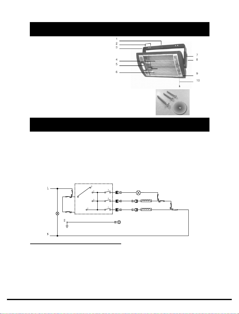
IMPORTANT INSTRUCTIONS
PLEASE READ ALL INSTRUCTIONS BEFORE USING THIS HEATER
NOTE: There may be a trace of smoke or odour when unit is first operated.
Do not be alarmed. This indicates that a drop of oil fell on the heating coil during
the manufacturing process. It will quickly evaporate and should not re-occur.
Make sure that the room in which the appliance is located is well ventilated during
this operation.
WHEN USING ELECTRICAL APPLIANCES, BASIC PRECAUTIONS SHOULD ALWAYS
BE FOLLOWED TO REDUCE RISK OF FIRE, ELECTRICAL SHOCK AND INJURY TO
PERSONS OR PROPERTY, INCLUDING THE FOLLOWING:
1. Read all instructions before using this heater.
2. This heater is hot when in use. To avoid burns, do not let bare skin touch hot surfaces.
Keep combustible materials, such as furniture, pillows, bedding, papers, clothes etc.
and curtains at least 3 ft.(0.9 m) from the front and top of the heater and keep them
away from the sides and rear (sides and rear restrictrions apply to location dedicated
heater only).
3. Extreme caution and reasonable supervision is necessary when any heater is used
by or near children, invalids or pets and whenever the heater is left operating and
unattended.
4. Always unplug heater when not in use. To disconnect, grip plug and pull from wall
outlet. Never yank on cord.
5. Do not operate any heater after it malfunctions. Disconnect power at service panel
and have heater inspected by a reputable electrician before reusing.
6. Do not use outdoors. This product is intended for normal household use only. Do not
use in construction sites, barns or other industrial areas where there are excessive
dust to create a fire hazard.
7. This heater is not intended for use in bathrooms, laundry areas and similar indoor
locations. Never locate heater where it may fall into a bathtub or other water container.
8. Do not run cord under carpeting.Do not cover cord with throw rugs, runners or the like.
Arrange cord away from traffic area where it will not be tripped over. Route the cord
so that it will not be walked on, or pinched by furniture.
9. To disconnect the heater, turn controls to “OFF”, and turn off power to heater circuit
at main disconnect panel (or operate internal disconnect switch if provided).
10.Connect to properly grounded outlets only.
11.Connect to a properly grounded, 3-prong outlet only. Do not connect the heater to
extension cords, surge protectors, timers, direct breakers, or an outlet with other
appliances connected to the same outlet. Risk of fire, overheat, malfunction, property
damage, injury, or even death may result if not adhered to!
12.Do not insert or allow foreign objects to enter any ventilation or exhaust opening as
this may cause an electric shock, fire or damage to the heater.
13.To prevent a possible fire, do not block air intakes or exhaust in any manner. Do not
use on soft surfaces, like a bed, where openings may become blocked.
14.A heater has hot or arcing or sparking pads inside. Do not use it in areas where
gasoline, paint or flammable liquids are used or stored.
15.Use this heater only as described in this manual. Any other use not recommended by
the manufacturer may cause fire, electric shock, injury to persons or other damage
to property.
16.This heater must be plugged into a 120V, 15 amp (or more) circuit of its own. Nothing
else can be plugged into the same circuit. If unsure if you home meets this
specification, consult a certified electrician prior to use. Risk of fire, overheat,
malfunction, property damage, injury, or even death may result if not adhered to!
10
STORAGE
1. Perform the cleaning procedures described in “Cleaning/Maintenance”.
2. Wipe all parts to dry.
3. Remove the heater from the mounting bracket and tape screws to the unit.
4. Pack the heater in a plastic bag and store it in a cool, dry place.
Interior Cleaning:
The most common cause of overheating is deposits of dust or fluff entering the
heater. Interior dust can be removed by following:
1. Remove heater from the mounting bracket. Set heater on table.
2. Remove the six screws located at the front of the guard, then the carefully remove
guard.
3. Wipe interior: Carefully wipe the surface of the interior with a DRY cloth.
4. Close the safety grille: Secure back to the heater by closing screen and re-installing
the screws.
5. Re-installation: Attach the heater back onto the mounting bracket and lock together
to secure.
Exterior Cleaning:
1. Use a clean, soft and lightly moistened (NOT DRIPPING WET) cloth to gently wipe
off the dirt from the surface of the unit.
2. Be sure not to wet the heating element and the switches.
3. Allow the unit to dry completely before using it.
CAUTION: DO NOT ALLOW WATER TO RUN INTO THE INTERIOR OF THE HEATER
AS THIS COULD CREATE A FIRE OR ELECTRIC SHOCK HAZARD, DAMAGING THE
UNIT.