Ventrac KH500 Versa-Loader User manual

Revised 04/15/14
09.10020 Rev. 02
VERSA-LOADER
Model KH500
OWNER/OPERATOR’S
MANUAL & PARTS LIST

ii
TO THE OWNER
Venture Products Inc. reserves the right to make changes in design or
specifications without incurring obligation to make like changes on
previously manufactured products.
Orrville, OH
www.ventrac.com
Model # (A): _______________________
Serial # (B): ________________________
Affix Part/Serial Number label here
Product Identification
If you need to contact an Authorized Ventrac Dealer for information on servicing your product,
always provide the Product Model and Serial numbers.
Please fill in the following information for future reference. See picture below to find the
location of the identification number. Record them in the spaces provided below.
Date of Purchase: Month _________________ Day ___________ Year ___________________
Dealer: _______________________________________________________________________
Dealer Address: ________________________________________________________________
________________________________________________________________
Dealer Phone Number: __________________________________________________________
Dealer FAX Number: ____________________________________________________________

TABLE OF CONTENTS
INTRODUCTION SECTION A
Description & Specifications ...............................A-1
SAFETY SECTION B
Safety Symbols ......................................B-1
Decals ..........................................B-2
General Safety Procedures ................................B-3
Safety Operation & Techniques..............................B-4
SETUP & OPERATION SECTION C
Setup .........................................C-1&2
Attaching .......................................C-2&3
Detaching .........................................C-3
Operating .........................................C-4
MAINTENANCE & SERVICE SECTION D
Maintenance .......................................D-1
PARTS & ILLUSTRATED DRAWINGS SECTION E
Main Frame & Loader Arms .............................E-1&2
Tool Mount Plate ...................................E-3&4
Hydraulic Pump & Valve ...............................E-5&6
Hydraulic Lift .....................................E7&8
Hydraulic Tilt ....................................E9&10
Buckets & Tine Fork ................................E11&12
Pallet Forks & Lift Boom ..............................E13&14
Hydraulic Diagram .................................E15&16
WARRANTY
iii

INTRODUCTION
Ventrac KH500 Versa-Loader Specifications
Overall Height on Tractor ........................ 67inches
Overall Width ..................................41inches
Overall Length with Standard Bucket......................69inches
Overall Length - Tractor, Loader, & Standard Bucket.............111inches
Width of Standard Bucket ............................48inches
Capacity of Standard Bucket (struck) ....................5cubic feet
Weight without Tools .............................470pounds
Lift Capacity including Tool ..................... 500pounds
Lift Height at Pivot Pins ......................... 77inches
Oil Tank Capacity .................................8gallons
Gallons/minute at 3600 RPM ...........................9.5GPM
A-1
Product Description
KH500
The KH500 front end versa-loader attachment is designed to give you, the owner, more
versatility with your Ventrac tractor. It is a universal tool for moving and loading material,
digging, leveling, and boring holes.
The loader is designed and built with all-steel construction, making it strong and rugged. It
has an independent hydraulic pump and oil reservoir, with two inch cylinders for lifting and
dumping.
The loader features:
- Quick attach to the tractor, installing or removing in three minutes or less
- Raised cross bar for added operator protection
- Joystick hydraulic valve control with float position
- Quick attach toolbar for changing quickly to different front tools
- 500 pound lift capacity including front tool
Options for the loader include:
- Buckets
- Forks
- Auger drive
- Counter weight bars
- Rear weights

SAFETY
B-1
ATTENTION:
This symbol identifies potential health and
safety hazards. It marks safety
precautions. Your safety and the safety of
others is involved.
SIGNAL WORD DEFINITIONS
Indicates a potentially hazardous situation
which, if not avoided, may result in minor
or moderate injury and/or property
damage. It may also be used to alert
against unsafe practices.
Indicates a potentially hazardous situation
which, if not avoided, could result in death
or serious injury.
Indicates an imminently hazardous
situation which, if not avoided, will result in
death or serious injury. This signal word is
limited to the most extreme cases.

B-2
SAFETY
B
A
Decal Page &
Location Description Part Number
AE-1, #35 Warning Loader Roll Bar 00.0194
BE-1, #37 Danger Loader 00.0193
CE-7, #16 Caution Loader Arms 00.0195
DE-1, #34 Warning, Read Owner's Manual 00.0217
C
The following decals must be maintained on your Ventrac Attachment. If any decals
are faded or missing, contact your dealer promptly for replacements.
D

B-3
SAFETY
General Safety Procedures
for Ventrac Tractors, Attachments, & Accessories
Read and understand the operator’s manual before operating this equipment.
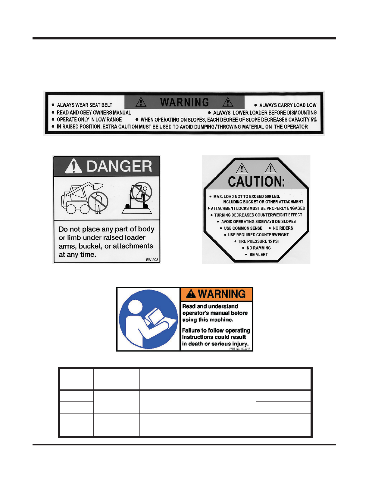
Observe and follow all safety decals.
DO NOT let children or any untrained person operate the tractor or attachment. Make sure
that all operators of this equipment are thoroughly trained in using it safely.
Never allow additional riders on the tractor or attachments.
DO NOT operate tractor or attachments if you are under the influence of alcohol, drugs,
medication that may impair judgment or cause drowsiness, or if you are not feeling well.
Operate all controls from the operator's seat only.
Before operating equipment, make sure all shields are in place and fastened.
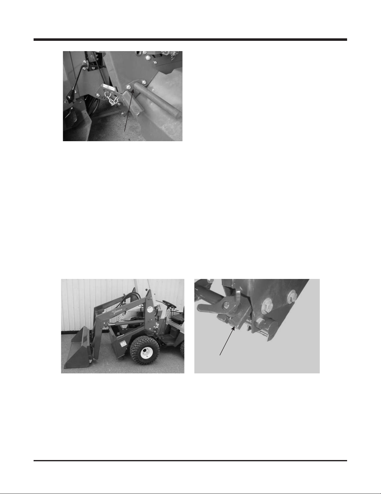
Ensure the attachment or accessory is locked or fastened securely to the tractor before
operating. See tractor manual for locking procedure.
Ensure that all bystanders are clear of the tractor and attachment before operating. Be
especially careful and observant if other people are present. Never assume that bystanders
will remain where you last saw them.
Always look in the direction the tractor is moving.
Never direct the discharge of any attachment in the direction of people, animals, buildings,
vehicles, or objects of value.
Immediately stop at any sign of equipment failure and correct the problem before
continuing to operate. An unusual noise can be a warning of equipment failure.
Before adjusting, cleaning, lubricating, or changing parts on the tractor or attachment,
engage the parking brake, lower the attachment to the ground, stop the engine, and
remove the ignition key.
To prevent the risk of uncontrolled equipment movement on tractors equipped with 2 speed
axles, always shift the transaxle range with the tractor stationary on level ground and with
the parking brake engaged.
If equipment is to be left unattended, engage the parking brake, lower the attachment to the
ground, stop the engine, and remove the ignition key.

SAFETY
B-4
KH500 Safety Procedures
Be sure attachment is locked securely to tractor (power unit) and accessory tool is locked
securely to tool mount bar before operating.
When operating on slopes, each degree of slope reduces capacity approximately 5%.
Avoid operating sideways on slopes. Turning decreases counterweight effect.
Always carry load low, and always lower loader before dismounting from tractor.
Additional rear counterweight must be used when operating loader. (6 weights or 250
pounds)
When loader is in a raised position, extra caution must be used to avoid dumping or
throwing material back on the operator.
Always have an accessory tool attached to the loader before removing from the tractor.
DO NOT place any part of body or limb under raised loader arms, bucket, or accessory
tools at any time.
Always lower the loader arms completely before opening the tractor hood. Never operate
loader with tractor hood open or hood may be damaged.
Before making any repairs or adjustments, lower
attachment to the ground, set parking brake, shut
the engine off, and remove the key.
Read and understand the operator’s manual before
operating this equipment.
Dual wheels must not be used with the
Versa-Loader. Using dual wheels in
conjunction with the Versa-Loader will
void the warranty on all transaxle and
axle components.

C-1
SETUP & OPERATION
Setup Instructions for KH500 Front End Versa-Loader:
1. Remove crating from around loader and remove crating brackets. With an
overhead hoist, lift loader clear of crate and set on level surface. Mount bucket
to tool bar and engage locking pins.
Fig. 1 Fig. 2
Fig 3 Fig 4
2. With hoist attached to rear cross bar,
and joystick in float position, raise
loader up until the loader arm locking
device (Fig 1)(Page E-1, Ref #9) can
be engaged.
3. Attach rear anchor brackets to loader
frame. (Fig 2)(Page E-1, Ref #22) Do
not tighten until later, when loader
has been completely mounted to the
tractor and the locking clamps have
been tightened to the shaft.
4. Install belt on drive pulley and
hook into notch near right hitch arm.
(Fig 3)
5. Purchase and install front/rear
connector support (64.1018) on
tractor, if not previously equipped.
(Fig 4) Tractors manufactured after
serial #1184 are already equipped
with this support.

C-2
SETUP & OPERATION
Operation
Attaching Versa-Loader:
Fig 5
Fig 6 Fig 7
6. Slide loader mounting shaft through
tractor frame from either side, just
above the foot pegs, and install bolts
in shaft mounting flange. Slide
clamping flange on opposite side
and bolt to frame. (Fig 5)(Page E-1,
Ref #24, 25) Note: The holes of the
clamping flange will not align
perfectly with the holes on the
tractor. This is by design, so when
the bolts are tightened, the flange
locks the shaft to the frame.
1. Drive tractor slowly into loader,
aligning the hitch arms until fully
engaged. (Fig 6) Note: A slight back
and forth movement of the steering
wheel and raising and lowering of the
front hitch may be needed to fully
engage hitch.
2. Engage the front hitch locks.
3. Set the parking brake.
4. Raise the front hitch until the rear
anchors engage the mounting shaft.
Note: Keep lock plates (Fig 7)(Page
E-1, Ref #32) clear of shaft when
rear anchors engage shaft.
5. Shut off engine.

C-3
SETUP & OPERATION
Detaching Versa-Loader:
Fig 8
6. Slip lock plates above pins on the
rear anchors and tighten wing nut.
(Fig 8)
7. Tighten the bolts holding the rear
anchors to the loader frame. (Fig 2)
Note: This step is only required
during initial attachment. Do not
loosen these bolts when detaching.
8. Install belt on front groove of drive
pulley on tractor and engage
tightener.
9. Start engine and raise loader. Return
loader arm locking device to its
storage position.
10. Install counter weights on tractor.
(Fig 9) (6 of 47.0115 weights)
11. Move rear mount of the steering
cylinder to the outer hole.
12. Adjust tire pressure up to 15 PSI.
Fig 9
1. Raise loader arms approximately 24”
and raise front hitch slightly.
2. Shut off tractor engine and set park-
ing brake.
3. Remove counter weights from tractor.
4. Lower loader arm locking device.
(Fig1)
5. Lower loader arms leaving joystick in
float position.
6. Loosen rear anchor lock bolts and re-
move lock plates from above retain-
ing pins.
7. Disengage belt tightener and remove
belt from drive pulley. Hook belt into
notch on loader frame. (Fig 3)
Fig 10
8. Start tractor and lower front lift until
loader sets on the ground. (Fig 6)
Note: If bucket does not set flat on
ground, move joystick sideways until
it sets flat. DO NOT remove loader
from tractor without an accessory
tool attached to balance the loader.
9. Open front hitch locks and back trac-
tor away from the loader. (Fig 10)

C-4
SETUP & OPERATION
Operating Techniques and Tips:
The front end loader can be a great tool for performing many tasks, such as moving and
loading material. Because of the nature of a front end loader to lift material to a high position
and change the center of gravity, it is necessary to keep SAFETY as the FIRST PRIORITY.
Always lower the loader, shut off the engine, and remove the key from the tractor when
cleaning or making adjustments on the loader or when leaving the tractor unattended.
Operator must be sitting on the tractor seat before the PTO can be engaged. Seat belt must
always be worn for safety.
Carry the load low, close to the ground.
Do not operate without proper counter weight. In addition to the standard four weights (three
weights with a 3-point hitch), adding six weights (47.0115) or 250 pounds is required.
Always use low range when operating the loader.
Before removing the loader from the tractor, always remove the counter weights.

D-1
MAINTENANCE & SERVICE
Maintenance
•The front end loader has twelve grease fittings. Two are located at the loader arm pivots,
two at the tool bar pivots, and one on the end of each cylinder. Grease with one/two
pumps of grease every 25 to 30 hours. If conditions are very severe, more may be
required.
•The hydraulic oil level should be maintained between the upper and lower notches on the
dipstick. The oil tank holds approximately eight gallons of oil. Use Ventrac Hydro•Torq XL
hydraulic oil or equivalent.

ILLUSTRATED DRAWING
MAIN FRAME & LOADER ARMS
PARTS
E-1

MAIN FRAME & LOADER ARMS
PARTS
E-2
REF. PART NO. DESCRIPTION QTY.
1 .....90.0606 ...........3/8-16 x 3/4 Bolt .......................... 12
2 .....95.06 ............3/8SAEFlat Washer ........................ 16
3 .....62.0948 ...........Roll Bar................................ 1
4 .....99.SF06 ..........3/8-16 Flange Nut.......................... 12
5 .....29.GF0001 .........1/4-28 Grease Fitting......................... 4
6 .....99.A04 ...........1/4-20 Lock Nut ........................... 2
7 .....64.0826 ...........Hose Clamp ............................. 1
8 .....90.0410 ...........1/4-20 x 1-1/4 Bolt .......................... 1
9 .....64.1021 ...........Cylinder Safety Prop ......................... 2
10.....03.0011 ...........3/8x2-1/2 Ball Pin .......................... 2
11.....90.0624 ...........3/8-16 x 3 Bolt ............................ 2
12.....99.A06 ...........3/8-16 Lock Nut ........................... 2
13.....62.0946 ...........LiftArmFrame Weldment ...................... 1
14.....23.0127 ...........OilTankDipstick ........................... 1
15.....00.0193 ...........Decal, Danger - Loader ....................... 1
16.....62.0945 ...........Main Frame Weldment ........................ 1
17.....64.1024 ...........3-3/4” Pivot Pin............................ 2
18.....95.05 ............5/16 SAE Flat Washer ........................ 2
19.....90.0506 ...........5/16-18 x 3/4 Bolt .......................... 2
20.....90.0808 ...........1/2-13 x 1 Bolt ............................ 8
21.....95.08 ............1/2SAEFlat Washer ......................... 8
22.....62.0947 ...........Main Frame Rear Mount ....................... 2
23.....99.SF08 ..........1/2-13 Flange Nut .......................... 8
24.....64.1029 ...........Mounted Attachment Bar Clamp ...................1
25.....42.0455 ...........Mounted Attachment Bar....................... 1
26.....90.0412 ...........1/4-20 x 1-1/2 Bolt .......................... 1
27.....64.0673 ...........Hose Clamp ............................. 1
28.....99.SF05 ..........5/16-18 Flange Nut.......................... 2
29.....99.A08 ...........1/2-13 Lock Nut ........................... 2
30.....90.0824 ...........1/2-13 x 3 Bolt ............................ 2
31.....42.0453 ...........Rear Mount Plate Bolt ........................ 2
32.....64.1019 ...........Rear Mount Plate .......................... 2
33.....00.0195 ...........Decal, Caution - Loader Frame ................... 2
34.....00.0217 ...........Decal, Warning Read Owners Man ................. 1
35.....00.0194 ...........Decal, Warning - Loader Roll Bar .................. 1
36.....00.0189 ...........Decal, Ventrac - Small Orbital .................... 2
37.....64.1077 ...........Rear Mount Locking Handle ..................... 2
38.....00.0100 ...........Decal, Made in USA ......................... 1
39.....29.P06H ..........Pipe, Plug 3/8 Hex ZP ........................ 1

ILLUSTRATED DRAWING
TOOL MOUNT PLATE
PARTS
E-3

TOOL MOUNT PLATE
PARTS
E-4
REF. PART NO. DESCRIPTION QTY.
1 .....62.0949 ...........Universal Attachment Mount ..................... 1
2 .....90.0410 ...........1/4-20 x 1-1/4 Bolt .......................... 2
3 .....90.0408 ...........1/4-20 x 1 Bolt ............................ 3
4 .....64.1027 ...........Universal Mount Attachment Pin ...................2
5 .....99.A04 ...........1/4-20 Lock Nut ........................... 4
6 .....41.0073 ...........Compression Spring - 1” OD x 2-1/2 .................2
7 .....42.0454 ...........Attachment Connecting Link ..................... 2
8 .....90.0608 ...........3/8-16 x 1 Bolt ............................ 2
9 .....99.SF06 ..........3/8-16 Flange Nut .......................... 6
10.....90.0506 ...........5/16-18 x 3/4 Bolt .......................... 2
11.....06.0051 ...........Plastic Cap .............................. 1
12.....64.1025 ...........4-3/8” Pivot Pin............................ 2
13.....99.SF05 ..........5/16-18 Flange Nut.......................... 3
14.....85.B0068 ..........3/8IDx1/2ODx5/8Bushing .................... 2
15.....40.0305 ...........Attachment Link Handle ....................... 1
16.....90.0620 ...........3/8-16 x 2-1/2 Bolt .......................... 1
17.....99.SF04 ..........1/4-20 Flange Nut .......................... 2

ILLUSTRATED DRAWING
HYDRAULIC PUMP & VALVE
PARTS
E-5

HYDRAULIC PUMP & VALVE
PARTS
E-6
REF. PART NO. DESCRIPTION QTY.
1 .....22.0035 ...........Hydraulic Hose Assembly - 5/8 x 28 ................. 1
2 .....25.2404-10-12 .......Hydraulic Fitting, Connector - 5/8 x 3/4 ...............1
3 .....21.0057 ...........Filter Head .............................. 1
4 .....21.0078 ...........10Micron Hydraulic Filter ...................... 1
5 .....05.0060 ...........Rubber Grommet........................... 2
6 .....99.SF06 ..........3/8-16 Flange Nut .......................... 7
7 .....20.0192 ...........Hydraulic Hose Assembly - 1/2 x 54 ................. 1
8 .....25.6400-08-10 .......Hydraulic Fitting, Connector - 1/2 x 5/8 ...............2
9 .....21.0105 ...........Hydraulic Pump ........................... 1
......89.0078 ...........Kit, Seal For 21.0105......................... 1
10.....99.A06 ...........3/8-16 Lock Nut ........................... 2
11.....95.06 ............3/8SAEFlat Washer ......................... 4
12.....99.SF0606 .........3/8-16 x 3/4 Flange Bolt ....................... 2
13.....64.1032 ...........Pump Mount Plate .......................... 1
14.....85.K0310 ..........3/16 x 1-1/4 Key ........................... 1
15.....81.B033...........B33Belt ............................... 1
16.....83.H12 ...........3/4” H Bushing ............................ 1
17.....83.BK60H..........6”H-Bushing Pulley ......................... 1
18.....90.0608 ...........3/8-16 x 1 Bolt ............................ 2
19.....90.0614 ...........3/8-16 x 1-3/4 Bolt .......................... 2
20.....25.6802-10-10 .......Hydraulic Fitting, 45° - 5/8 x 5/8 ...................1
21.....23.0120 ...........Joystick Valve ............................ 1
22.....64.1033 ...........Joystick Valve Plate ......................... 1
23.....95.05 ............5/16 SAE Flat Washer ........................ 3
24.....96.05 ............5/16 Lock Washer .......................... 3
25.....90.0506 ...........5/16-18 x 3/4 Bolt .......................... 6
26.....99.SF05 ..........5/16-18 Flange Nut.......................... 3
27.....25.6802-12-12 .......Hydraulic Fitting, 45° - 3/4 x 3/4 . . . . . . . . . . . . . . . . . . . . . 1
28.....22.0036 ...........Hydraulic Hose Assembly - 3/4 x 10 .................1
29.....25.6500-12-12 .......Hydraulic Fitting, 90° - 3/4 x 3/4 ................... 1
30.....25.2404-12-12 .......Hydraulic Fitting, Connector - 3/4 x 3/4 ...............1

ILLUSTRATED DRAWING
HYDRAULIC LIFT
PARTS
E-7
Other manuals for KH500 Versa-Loader
1
Table of contents
Other Ventrac Tractor Accessories manuals
Popular Tractor Accessories manuals by other brands

Avantco
Avantco A427450 Operator's manual for Attachment

Avantco
Avantco A411401 Operator's manual for Attachment

Degelman
Degelman Landroller Operator's & parts manual

Tektite
Tektite Toro GM328 Operation manual

LS tractor
LS tractor LS3150-B Operator and parts manual

Original Tractor Cabs
Original Tractor Cabs CAB 12152 Assembly instructions

Toro
Toro 08720 installation instructions

matev
matev SRM-VP 130 Original operating manual

Alamo
Alamo Schulte SRW 1400 OPERATOR’S MANUAL WITH PARTS LISTING

EPI
EPI ENVIRO Cover Deployer 800 Operation and service manual

Sears
Sears CRAFTSMAN C 151 61581 0 owner's manual

Toro
Toro Greensmaster 04654 Series Operator's manual