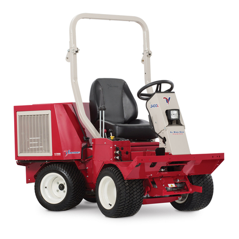
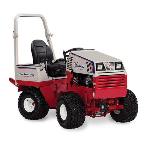
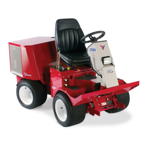
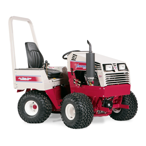
Ventrac 4520Z User manual

Service Manual
4520Z
Serial Numbers 01001–05664
09.40001Rev 00 Original Instructions (EN)

Reader Comments
Ventrac maintains a continuous effort to improve the quality and usefulness of its
publications. To do this effectively, we encourage user feedback. Please comment on
the completeness, accuracy, organization, usability, and readability of this manual by
or Mail to:
Technical Publications, Service
Ventrac by Venture Products Inc.®
500 Venture Drive Orrville, OH 44667
Phone: 1–866–836–8722
: Page 2 4520Z
09.40001Rev 00

Preface
The purpose of this publication is to provide a trained service technician with the
information for troubleshooting, testing, and repair of the Ventrac 4520 series
machines.
Refer to the Operator’s Manuals for operating, maintenance, and adjustment
instructions. Refer to the Part’s Manual for specific part information. Additional copies
of the Operator’s and Part’s manuals are available at www.Ventrac.com under
resources.
Venture Products Inc.® and Ventrac reserve the right to change the product
specifications or this publication without notice.
DANGER
This symbol indicates an imminently hazardous situation which, if not avoided,
will result in death or serious injury. This signal word is limited to the most
extreme cases.
WARNING
This symbol indicates a potentially hazardous situation which, if not avoided
could result in death or serious injury.
CAUTION
This symbol indicates a potentially hazardous situation which, if not avoided,
may result in minor or moderate injury and/or property damage. It may also be
used to alert against unsafe practices.
IMPORTANT
The important notice will give the important instructions which must be
followed to prevent damage to equipment.
Note: A note will give the general information about the correct operation,
maintenance, service, testing, or repair of the machine.
Preface: Page 4 4520Z
09.40001Rev 00

Service Procedure Icons
The following icons appear throughout this service manual to bring attention to
specific important details of a service procedure.
Critical Process is used to highlight:
• installing safety equipment (shields, guards, seat belts, brakes and R.O.P.S.
components) that may have been removed
• dimensions or settings that must be maintained for proper machine operation
• a specific fastener tightening sequence
• component orientation that may not be obvious
Critical Torque
This icon is used to highlight an assembly torque requirement that is different
than what is recommended in the Standard Torque Tables; refer to Torque
Specifications, page 2–4.
Fluid Specifications is used to highlight fluid specifications and capacities that
are less common, and may not appear on the machine service decal or in the
machine Operator’s Manual
Note: Refer to the service decal on the machine and the machine Operator’s Manual
for commonly used fluid specifications and capacities.
Safety and Instructional Decals
There are many safety and instruction decals affixed to the Ventrac 4520. If any
decals become illegible or damaged, install a new decal. Decal part numbers are
listed in the Parts Manual. Order replacement decals from an Authorized Ventrac
Dealer.
4520Z Preface:
09.40001Rev 00

Table of Contents
Preface ............................................................................................................................................ 4
Chapter 1: General Safety Instructions .............................................................................. 1–1
Before Operating the Machine Safety............................................................................. 1–2
While Operating the Machine Safety............................................................................... 1–3
Maintenance and Service Safety ..................................................................................... 1–4
Jacking Instructions............................................................................................................. 1–6
Raising the Front of the Machine ................................................................................. 1–6
Raising the Rear of the Machine .................................................................................. 1–8
Chapter 2: Specifications ....................................................................................................... 2–1
4520Z Specifications........................................................................................................... 2–2
Fluid Capacities and Specifications............................................................................. 2–2
4520Z Engine Specifications......................................................................................... 2–3
Hydraulic System ............................................................................................................. 2–3
Torque Specifications.......................................................................................................... 2–4
Fastener Identification .................................................................................................... 2–4
Fasteners with a Locking Feature.................................................................................... 2–5
Calculating the Torque Values When Using a Drive-Adapter Wrench ................ 2–5
Standard Torque Specifications Table for SAE J429 Grade 2 Steel
Fasteners........................................................................................................................... 2–7
Standard Torque Specifications Table for SAE J429 Grade 5 Steel
Fasteners........................................................................................................................... 2–8
Standard Torque Specifications Table for SAE J429 Grade 8 Steel
Fasteners........................................................................................................................... 2–9
Standard Torque Specifications Table for ASTM F593 Stainless Steel Hex
Cap Screw ....................................................................................................................... 2–10
Standard Torque Specifications Table for Metric Class 8.8 Steel Fasteners... 2–12
Standard Torque Specifications Table for Metric Class 10.9 Steel
Fasteners......................................................................................................................... 2–13
Standard Torque Specifications Table for Metric A2–70 or A4–70 Stainless
Steel Fasteners .............................................................................................................. 2–14
Shop Supplies..................................................................................................................... 2–15
Special Tools ....................................................................................................................... 2–18
Chapter 3: Troubleshooting ................................................................................................... 3–1
GEARS – The Systematic Approach to Defining, Diagnosing and Solving
Problems................................................................................................................................ 3–2
General Hydraulic System Problems .............................................................................. 3–3
General Electrical System Problems............................................................................... 3–6
General Engine Problems.................................................................................................. 3–8
Chapter 4: Engine.................................................................................................................... 4–1
General Engine Information .............................................................................................. 4–2
4520 Operator’s Manual................................................................................................. 4–2
Kubota Service Manuals ................................................................................................ 4–2
Engine Service and Repairs.............................................................................................. 4–3
Air Cleaner System.......................................................................................................... 4–3
4520Z Removing and Installing the Air Cleaner System............................................ 4–4
Exhaust System ............................................................................................................... 4–5
4520Z Removing the Exhaust System ........................................................................... 4–6
4520Z Installing the Exhaust System.............................................................................. 4–7
Fuel System ...................................................................................................................... 4–8
Checking the Fuel Lines and Connections .................................................................... 4–9
Priming the Fuel System .................................................................................................. 4–10
Preface: Page 6 4520Z
09.40001Rev 00

Removing and Installing the Fuel Tank......................................................................... 4–11
Removing the Fuel Pump ................................................................................................ 4–13
Installing the Fuel Pump................................................................................................... 4–14
Engine Cooling System ................................................................................................ 4–15
4520Z Removing the Radiator........................................................................................ 4–16
4520Z Installing the Radiator .......................................................................................... 4–17
Engine............................................................................................................................... 4–17
Chapter 5: Hydraulic System ................................................................................................ 5–1
General Information............................................................................................................. 5–2
4520 Operator’s Manual and Accessory Installation Instructions ........................ 5–2
Towing the 4520 ............................................................................................................... 5–2
Relieving Pressure from the Hydraulic System ........................................................ 5–2
Remote Filtering the Hydraulic System ...................................................................... 5–3
Testing the Static Implement Pressure ....................................................................... 5–5
Testing the Hydrostatic Drive System Under Load .................................................. 5–5
Testing the Steering Valve P-Port Bypass ................................................................. 5–6
Adjusting the Hydraulic Pump Tow Valve................................................................... 5–7
Hydraulic Hoses ................................................................................................................... 5–9
Installing the Hydraulic Hoses and Tubes (O-Ring Face Seal)........................... 5–10
Installing the Hydraulic Fittings (SAE Straight Thread O-Ring Fittings)............ 5–12
Hydraulic Schematic ......................................................................................................... 5–16
Hydraulic Flow Diagrams ................................................................................................. 5–17
Drive Circuit..................................................................................................................... 5–17
Implement Circuit ........................................................................................................... 5–18
Service and Repairs.......................................................................................................... 5–19
General Precautions for Removing and Installing Hydraulic System
Components.................................................................................................................... 5–19
Removing the Front Hydraulic Motor ........................................................................ 5–21
Installing the Front Hydraulic Motor........................................................................... 5–22
Removing the Rear Hydraulic Motor ......................................................................... 5–22
Installing the Rear Hydraulic Motor............................................................................ 5–23
Removing the Hydraulic Pump ................................................................................... 5–24
Installing the Hydraulic Pump ..................................................................................... 5–26
Removing the SDLA Spool Valve............................................................................... 5–27
Installing the SDLA Spool Valve................................................................................. 5–27
Replacing the SDLA Spool Valve Float Detent....................................................... 5–28
Removing and Installing the Hydraulic Cooler Fan................................................ 5–29
Removing and Installing the Steering Valve ............................................................ 5–30
Removing the Steering Cylinder................................................................................. 5–32
Installing the Steering Cylinder................................................................................... 5–33
Removing the Lift Cylinder........................................................................................... 5–33
Installing the Lift Cylinder............................................................................................. 5–34
Removing the 3–Point Hitch Spool Valve................................................................. 5–35
Installing the 3–Point Hitch Spool Valve ................................................................... 5–35
Removing the 3–Point Hitch Lift Cylinder................................................................. 5–36
Installing the 3–Point Hitch Lift Cylinder................................................................... 5–37
Removing and Installing the Hydraulic Fluid Reservoir ........................................ 5–38
Chapter 6: Electrical System................................................................................................. 6–1
General Information............................................................................................................. 6–3
4520 Operator’s Manual and Accessory Installation Instructions ........................ 6–3
Kubota Engine Electrical Components ....................................................................... 6–3
Amperage Draw Chart .................................................................................................... 6–4
Electrical Drawings .............................................................................................................. 6–5
4520Z Preface:
09.40001Rev 00

Electrical System Quick Checks....................................................................................... 6–6
Testing the Charging System ........................................................................................ 6–6
Checking the Operation of the Interlock Switches ................................................... 6–6
Electrical Component Testing ........................................................................................... 6–9
Fuses .................................................................................................................................. 6–9
Relays............................................................................................................................... 6–15
Tractor Control Module (TCM)........................................................................................ 6–19
Removing and Installing the TCM.............................................................................. 6–20
Tractor Control System (TCS) ........................................................................................ 6–21
Removing and Installing the TCS............................................................................... 6–22
Information Gauge Cluster .............................................................................................. 6–23
Programming the Gauge ................................................................................................. 6–24
Power Relay Module ......................................................................................................... 6–26
Fusible Link Harness......................................................................................................... 6–27
Testing the Fusible Link Harness ............................................................................... 6–27
Key Switch ........................................................................................................................... 6–28
Testing the Key Switch...................................................................................................... 6–29
Power Take Off (PTO) Enable Switch........................................................................... 6–29
Testing the Power Take Off (PTO) Switch.................................................................... 6–30
Seat Switch.......................................................................................................................... 6–31
Testing the Seat Switch ................................................................................................ 6–31
Headlight Switch ................................................................................................................ 6–32
Testing the Headlight Switch ........................................................................................... 6–33
Directional Signal Switch.................................................................................................. 6–33
Testing the Directional Signal Switch ............................................................................ 6–34
Hazard Flasher Switch...................................................................................................... 6–34
Testing the Hazard Flasher Switch ................................................................................ 6–35
Work Light Switch .............................................................................................................. 6–35
Testing the Work Light Switch......................................................................................... 6–36
Strobe Light Switch............................................................................................................ 6–36
Testing the Strobe Light Switch ...................................................................................... 6–37
Rear 12 Volt Switch ........................................................................................................... 6–37
Testing the Rear 12 Volt Switch...................................................................................... 6–38
Rear 12 Volt Momentary Switch ..................................................................................... 6–38
Testing the Rear 12 Volt Momentary Switch................................................................ 6–39
Parking Brake Switch........................................................................................................ 6–39
Testing the Parking Brake Switch................................................................................... 6–40
PTO Electric Clutch ........................................................................................................... 6–41
Testing the PTO Electric Clutch.................................................................................. 6–41
Warning Alarm .................................................................................................................... 6–43
Testing the Warning Alarm........................................................................................... 6–43
Neutral Switch..................................................................................................................... 6–44
Testing the Neutral Switch ............................................................................................... 6–45
Hydraulic Fluid Temperature Switches ......................................................................... 6–46
Testing the Front Motor Hydraulic Fluid Temperature Switch.............................. 6–46
Testing the Hydraulic Cooler Temperature Switch ................................................. 6–47
Hydraulic Cooler Fan ........................................................................................................ 6–49
Testing the Hydraulic Cooler Fan............................................................................... 6–49
Speed Sensor ..................................................................................................................... 6–51
Testing the Speed Sensor............................................................................................ 6–52
Adjusting the Speed Sensor........................................................................................ 6–53
RPM Sensor ........................................................................................................................ 6–54
Testing the RPM Sensor............................................................................................... 6–54
Preface: Page 8 4520Z
09.40001Rev 00
Adjusting the RPM Sensor........................................................................................... 6–55
Fuel Pump ........................................................................................................................... 6–56
Testing the Fuel Pump .................................................................................................. 6–56
Fuel Level Sender.............................................................................................................. 6–58
Testing the Fuel Level Sender .................................................................................... 6–58
Oil Pressure Switch ........................................................................................................... 6–60
Testing the Oil Pressure Switch.................................................................................. 6–60
Speed Direction Lift Auxiliary (SDLA) Control Lever (Optional) ............................. 6–62
Testing the SDLA Control Lever 12V Switches....................................................... 6–62
12 Volt Front and Rear Socket and Plug ...................................................................... 6–63
Battery .................................................................................................................................. 6–65
Battery Safety ................................................................................................................. 6–66
Cleaning the Battery and Terminals........................................................................... 6–66
Charging the Battery ..................................................................................................... 6–67
Storing the Battery ......................................................................................................... 6–67
Removing the Battery ................................................................................................... 6–68
Installing the Battery...................................................................................................... 6–68
Chapter 7: Chassis .................................................................................................................. 7–1
General Information............................................................................................................. 7–3
4520 Operator’s Manual and Accessory Installation Instructions ........................ 7–3
Adjustments........................................................................................................................... 7–4
Adjusting the PTO Belt Tension.................................................................................... 7–4
Adjusting the PTO Electric Clutch Air Gap................................................................. 7–4
Adjusting the Parking Brake .......................................................................................... 7–6
Adjusting Neutral.............................................................................................................. 7–7
Adjusting the Neutral Switch ........................................................................................ 7–9
Service and Repairs.......................................................................................................... 7–11
Removing and Installing the Wheels......................................................................... 7–11
Removing and Installing Outer Dual Wheels........................................................... 7–12
Removing and Installing the Hood............................................................................. 7–13
Removing and Installing the Grill ............................................................................... 7–14
Removing and Installing the Engine Covers ........................................................... 7–14
Removing and Installing the Hydraulic Pump Cover ............................................. 7–15
Removing and Installing the Right Hydraulic Pump Cover .................................. 7–16
Removing and Installing the Hydraulic Filter Access Cover ................................ 7–17
Removing and Installing the Lower Frame Cover.................................................. 7–18
Removing and Installing the Control Panel.............................................................. 7–19
Removing and Installing the Hydraulic Cooler Top Cover.................................... 7–20
Removing and Installing the Hydraulic Cooler Inner Cover................................. 7–21
Removing and Installing the SDLA Pivot Cover ..................................................... 7–22
Removing and Installing the Right Outer Seat Box Panel.................................... 7–23
Removing and Installing the Right Rear Seat Box Panel ..................................... 7–24
Removing and Installing the Fuel Tank Top Cover................................................. 7–25
Removing and Installing the Fuel Tank Inner Cover.............................................. 7–26
Removing and Installing the Left Outer Seat Box Panel ...................................... 7–27
Removing and Installing the Left Rear Seat Box Panel........................................ 7–28
Removing and Installing the Roll Bar ........................................................................ 7–29
Removing and Installing the Seat .............................................................................. 7–30
Removing and Installing the Seat Mount.................................................................. 7–31
Removing and Installing the Steering Wheel .......................................................... 7–32
Removing and Installing the Steering Valve Cover................................................ 7–33
Removing and Installing the Parking Brake Cover ................................................ 7–34
Removing the Dash....................................................................................................... 7–35
4520Z Preface:
09.40001Rev 00

Installing the Dash ......................................................................................................... 7–36
Removing the Weight Transfer Assembly................................................................ 7–37
Installing the Weight Transfer Assembly .................................................................. 7–38
Removing the Parking Brake Lever........................................................................... 7–39
Installing the Parking Brake Lever ............................................................................. 7–40
Removing the Parking Brake Band ........................................................................... 7–40
Installing the Parking Brake Band.............................................................................. 7–41
Removing the Parking Brake Drum ........................................................................... 7–41
Installing the Parking Brake Drum ............................................................................. 7–42
Removing the High / Low Shift Cable........................................................................ 7–43
Installing the High / Low Shift Cable.......................................................................... 7–43
Removing the Rear Weight Mount............................................................................. 7–44
Installing the Rear Weight Mount .............................................................................. 7–44
Removing the 3–Point Hitch........................................................................................ 7–45
Installing the 3–Point Hitch .......................................................................................... 7–45
Removing the Front / Rear Connector Link ............................................................. 7–46
Installing the Front / Rear Connector Link................................................................ 7–46
Removing the Connector Link Mount........................................................................ 7–47
Installing the Connector Link Mount .......................................................................... 7–47
Removing the Center Pivot.......................................................................................... 7–48
Installing the Center Pivot ............................................................................................ 7–49
Removing the Front Hitch Arms ................................................................................. 7–50
Installing the Front Hitch Arms.................................................................................... 7–50
Removing the PTO Idler Pulley .................................................................................. 7–51
Installing the PTO Idler Pulley..................................................................................... 7–51
Chapter 8: Axles....................................................................................................................... 8–1
General Information............................................................................................................. 8–2
4520 Operator’s Manual and Accessory Installation Instructions ........................ 8–2
Axle Assemblies................................................................................................................... 8–3
Service and Repairs............................................................................................................ 8–4
Removing the Front Axle Assembly ............................................................................ 8–4
Installing the Front Axle Assembly............................................................................... 8–5
Removing the Rear Axle Assembly ............................................................................. 8–6
Installing the Rear Axle Assembly ............................................................................... 8–8
Removing and Installing Front Axle Housing Assemblies...................................... 8–8
Removing and Installing Rear Axle Housing Assemblies ...................................... 8–9
Removing and Installing Axle Shafts......................................................................... 8–10
Axle Bearing Replacement .......................................................................................... 8–11
Axle Seal Replacement ................................................................................................ 8–12
Changing Rear Transaxle Fluid.................................................................................. 8–12
Chapter 9: Appendix A............................................................................................................ 9–1
Wiring Diagram Reference Key (Serial # 01001–02172) ........................................... 9–2
Wiring Diagram — Rear Harness (Serial # 01001–02172).................................... 9–3
Wiring Diagram — Front Harness (Serial # 01001–02172)................................... 9–4
Wiring Diagram — Engine Harness (Serial # 01001–02172)................................ 9–5
Wiring Diagram Reference Key (Serial # 02173–05664) ........................................... 9–6
Wiring Diagram — Rear Harness (Serial # 02173–05664).................................... 9–7
Wiring Diagram — Front Harness (Serial # 02173–05664)................................... 9–8
Wiring Diagram — Engine Harness (Serial # 02173–05664)................................ 9–9
Hydraulic Schematic ......................................................................................................... 9–10
Preface: Page 10 4520Z
09.40001Rev 00

Chapter 1
General Safety Instructions
Table of Contents
Before Operating the Machine Safety..................................................................................................... 1–2
While Operating the Machine Safety....................................................................................................... 1–3
Maintenance and Service Safety ............................................................................................................. 1–4
Jacking Instructions..................................................................................................................................... 1–6
Raising the Front of the Machine ......................................................................................................... 1–6
Raising the Rear of the Machine .......................................................................................................... 1–8
Ventrac equipment is tested and certified byVentrac for compliance with existing
safety standards and specifications. Although hazard control and accident prevention
partially are dependent upon the design and configuration of the machine, these
factors are also dependent on the awareness, concern, and proper training of the
personnel operating, and performing maintenance of the machine. Improper use or
maintenance of the machine can result in injury or death.
WARNING
To reduce the risk of a potentially hazardous situation, comply with all safety
instructions as well as the information found in the Operator’s Manual, and
accessory Installation Instructions.
4520Z Page 1–1 General Safety Instructions
09.40001Rev 00

Before Operating the Machine Safety
• Review and understand the operator’s manual before starting and operating the
machine. Additional copies of the operator’s manuals are available on the Ventrac
Dealer Network under resources or at www.Ventrac.com.
• Never allow children to operate the machine. Never allow adults to operate the
machine without proper training and instructions.
• Become familiar with the controls and know how to stop the machine and engine
(if equipped).
• Keep all shields, safety devices, and decals in place and in working order. Repair
and/or replace illegible decals, damaged shields, or safety devices before
operating the machine.
• Wear appropriate clothing. Do not operate the machine while wearing sandals,
tennis shoes or sneakers. Do not wear loose fitting clothing which may become
caught in moving parts and cause personal injury.
• Wearing safety glasses, hearing protection, safety shoes, and long pants is
advisable and may be required by local safety and insurance regulations.
• Make sure that work areas are clear of objects that may become picked up and
thrown by attachments.
• Keep the work areas clear of personnel including children and pets, stop and shut
off the machine if someone enters the work area.
• Ensure that the interlock switches are adjusted properly so that the engine cannot
be started unless the parking brake is engaged, the SDLA control is in neutral, and
the PTO is disengaged; refer to Checking the Operation of the Interlock Switches,
page 6–6.
• Fuel is highly flammable; use extreme care while handling fuel.
– Use an approved fuel container.
– Do not smoke while handling fuel.
– Always refuel the machine outdoors.
– Do not overfill the fuel tank.
– Clean up any spilled fuel in accordance with local regulations.
General Safety Instructions: Before Operating the
Machine Safety
Page 1–2 4520Z
09.40001Rev 00

While Operating the Machine Safety
• Remain seated when operating the machine.
• Always wear a seat belt if the machine has a roll cage/bar installed and in the
upright position.
• Ensure that all bystanders are clear of the machine and attachment before
operation.
• Stop operation immediately at any sign of equipment failure.
• Never shift between high and low range while on a slope. Always move the
machine to level ground and engage the parking brake before shifting the range.
• Never leave the machine unattended while it is running.
• Always shut off the machine when connecting the attachment drive belt to the
power unit.
• Never leave the operator’s station without lowering the attachment to the ground.,
engaging the parking brake, shutting off the engine, and removing the ignition key.
• Never direct the discharge of any attachment in the direction of people, buildings,
animals, vehicles or other objects of value.
• Never discharge material against a wall or obstruction. The material may ricochet
back toward the operator.
• Do not run the engine in a building without adequate ventilation.
• Do not touch the engine or the muffler while the engine is running or immediately
after stopping the engine.
4520Z Page 1–3 General Safety Instructions: While Operating the
Machine Safety
09.40001Rev 00

Maintenance and Service Safety
• Keep the safety decals legible. Remove all grease, dirt, and debris from the safety
decals and instructional labels.
• Always lower the attachment to the ground, engage the parking brake, shut off the
engine, and remove the ignition key. Make sure all moving parts have come to a
complete stop before cleaning, inspecting, adjusting, or repairing.
• Always turn the battery disconnect to the Off position or disconnect the battery
before performing any repairs. Disconnect the negative cable first and then the
positive cable. If battery voltage is necessary for troubleshooting or test
procedures, temporarily connect the battery. Connect the positive battery cable
and then the negative cable.
• Keep all bolts, nuts, screws, and other fasteners properly tightened.
• Never perform maintenance on the power unit and/or attachment if someone is in
the operator’s station.
• Always use protective glasses when handling the battery.
• Check the fuel lines for tightness and wear on a regular basis. Tighten or repair
them as needed.
• To reduce the hazard of fire, keep the battery compartment, engine, and muffler
areas free of grass, leaves, and excess grease.
• Do not touch the engine, the muffler, or other exhaust components while the
engine is running or immediately after stopping the engine. These areas may be
hot enough to cause a burn.
• Allow the engine to cool before storing and do not store near an open flame.
• Do not change the engine governor settings or over-speed the engine. Operating
engine at excessive speeds may increase the hazard of personal injury.
• Springs may contain stored energy. Use caution when disengaging or removing
springs and/or spring-loaded components.
• The hydraulic system may contain stored energy. Before performing maintenance
or repairs on the hydraulic system, remove any attachments, engage the parking
brake, disengage the weight transfer system (if equipped), shut off the engine, and
remove the ignition key. To relieve pressure on the auxiliary hydraulic system, shut
off the power unit engine and move the hydraulic control lever left and right before
disconnecting the auxiliary hydraulic quick couplers.
• Make sure the hydraulic connections are tight and all hydraulic hoses and tubes
are in good condition. Repair any leaks and replace any damaged or deteriorated
hoses or tubes before starting the machine.
• Keep your body and hands away from pinhole leaks or nozzles that eject high
pressure hydraulic fluid. Hydraulic fluid escaping under high pressure can
penetrate the skin causing serious injury, leading to severe complications and/or
secondary infections if left untreated. If hydraulic fluid is injected into the skin,
seek immediate medical attention no matter how minor the injury appears.
• An obstruction or blockage in a drive system or moving/rotating parts may cause a
buildup of stored energy. When the obstruction or blockage is removed, the drive
system or moving/rotating parts may move suddenly. Do not attempt to remove an
General Safety Instructions: Maintenance and Service
Safety
Page 1–4 4520Z
09.40001Rev 00

obstruction or blockage with your hands. Keep your hands, feet, and clothing
away from all power-driven parts.
• When changing the attachments, tires, or performing other service, use the
correct hoists, jacks, and jack stands, to raise and support the machine. Ensure
that the machine is parked on a solid level surface, such as a concrete floor.
Before lifting the machine remove all attachments. Failing to properly support the
raised machine with the appropriate jack stands can cause the machine to move
or fall and can result in personal injury; refer to Jacking Instructions, page 1–6.
• If welding on the machine is necessary, disconnect the battery negative cable to
prevent electrical system damage.
• Ensure potentially harmful waste (e.g., fuel, oil, engine coolant, filters, battery) are
disposed of in an environmentally safe manner in accordance with local
regulations.
• To ensure optimum performance and continued safety certification of the machine,
use genuine Ventrac replacement parts and accessories. Replacement parts and
accessories of other manufacturers can result in non-conformance of safety
standards and can void the warranty.
4520Z Page 1–5 General Safety Instructions: Maintenance and Service
Safety
09.40001Rev 00

Jacking Instructions
CAUTION
Failing to properly support the machine with appropriate jack stands can cause
the machine to move or fall and can result in personal injury.
When changing the attachments, tires, or performing other services, do the
following steps:
• Use correct blocks, hoists, and jacks to raise and support the machine.
• Park the machine on a solid level surface, such as a concrete floor.
• Before you lift the machine, remove all the attachments from the machine.
• Always block the wheels with chocks.
• Use appropriate jack stands to support the raised machine.
Raising the Front of the Machine
1. Remove all attachments from the machine.
2. Ensure that the front hitch arms are parallel to the ground as shown.
Figure 1
G415644
Hitch Arms
3. Park the machine on a level surface, engage the parking brake, and remove the
key from the ignition.
4. Block the rear wheels using wheel chocks to prevent the machine from rolling.
General Safety Instructions: Jacking Instructions Page 1–6 4520Z
09.40001Rev 00

Raising the Front of the Machine (continued)
Figure 2
G415138
Hitch Arm Frame Tube
Axle Housing
5. Position the jack securely under the hitch arm frame tube .
6. Lift the front of the machine to the desired height.
7. Position jack stands securely under the axle assembly .
Note: Removing the front wheels may be required to fit jack stands under the
axle assembly.
8. Lower the machine onto the jack stands and remove the jack.
4520Z Page 1–7 General Safety Instructions: Jacking Instructions
09.40001Rev 00

Raising the Rear of the Machine
1. Remove all attachments from the machine.
2. Remove all weights from the rear of the machine.
3. Park the machine on a level surface, engage the parking brake, and remove the
key from the ignition.
4. Block the front wheels using wheel chocks to prevent the machine from rolling.
Figure 3
G415151
Frame, Rear Weight Bar/
Hitch
Axle Assembly
5. Position the jack securely under the frame, rear weight bar/hitch .
6. Lift the rear of the machine to the desired height.
7. Position the jack stands securely under the axle assembly .
Note: Removing the rear wheels may be required to fit jack stands under the
axle housing.
8. Lower the machine onto the jack stands and remove the jack.
General Safety Instructions: Jacking Instructions Page 1–8 4520Z
09.40001Rev 00
Chapter 2
Specifications
Table of Contents
4520Z Specifications................................................................................................................................... 2–2
Torque Specifications.................................................................................................................................. 2–4
Fastener Identification ............................................................................................................................ 2–4
Fasteners with a Locking Feature............................................................................................................ 2–5
Calculating the Torque Values When Using a Drive-Adapter Wrench ........................................ 2–5
Standard Torque Specifications Table for SAE J429 Grade 2 Steel Fasteners ........................ 2–7
Standard Torque Specifications Table for SAE J429 Grade 5 Steel Fasteners ........................ 2–8
Standard Torque Specifications Table for SAE J429 Grade 8 Steel Fasteners ........................ 2–9
Standard Torque Specifications Table for ASTM F593 Stainless Steel Hex Cap Screw ...... 2–10
Standard Torque Specifications Table for Metric Class 8.8 Steel Fasteners........................... 2–12
Standard Torque Specifications Table for Metric Class 10.9 Steel Fasteners......................... 2–13
Standard Torque Specifications Table for Metric A2–70 or A4–70 Stainless Steel
Fasteners................................................................................................................................................. 2–14
Shop Supplies............................................................................................................................................. 2–15
Special Tools ............................................................................................................................................... 2–18
Venture Products Inc.® and Ventrac reserve the right to change these specifications
without notice.
4520Z Page 2–1 Specifications
09.40001Rev 00

4520Z Specifications
Note: Specifications and design are subject to change without notice.
Dimensions
Wheelbase 114 cm (45 inches)
Length 207 cm (81.5 inches)
Height (top of ROPS bar) 173 cm (68 inches)
Width (single tires)* 123 cm (48.5 inches)
Width (dual tires)* 185 cm (73 inches)
Weight** 773 kg (1,705 lb)
*May vary based on the tire size, type, and inflation.
**Weight varies based on the engine size, tire options, and optional accessories.
Fluid Capacities and Specifications
Fluid Type Capacity Filter #1 Filter #2
Engine Oil
(4520 K)
Synthetic 10W-
30
2.3 L (2.4 qt) 13.842921
Engine Oil
(4520 P)
Synthetic 10W-
30
1.9 L (2.0 qt) 13.0268
Engine Oil
(4520 Y)
Synthetic 10W-
30
3.7 L (3.9 qt) 13.0267
Engine Oil
(4520 Z)
Synthetic 10W-
30
2.8 L (3.0 qt) 13.0267
Engine Oil
(4520 N)
Synthetic 10W-
30
3.4 L (3.6 qt) 13.0267
Hydraulic Oil
(Front trans
axle and
reservoir)
HydroTorq XL
Synthetic
Hydraulic Oil
11.6 L (12.3 qt)
Optional 3–point
hitch
12.2 L (13 qt)
21.0122
(Suction Filter)
21.0124 (Return
Filter)
Hydraulic Oil
(Rear trans
axle)
HydroTorq XL
Synthetic
Hydraulic Oil
4.4 L (4.6 qt)
Cooling
System (4520
P,Y,Z,N)
50% distilled
water and 50%
ethylene glycol
antifreeze
6.6 L (7 qt)
Specifications: 4520Z Specifications Page 2–2 4520Z
09.40001Rev 00

This manual suits for next models
3
Table of contents
Other Ventrac Tractor manuals

Ventrac
Ventrac 3400L User manual

Ventrac
Ventrac 4200 VXD Owner's manual

Ventrac
Ventrac 4520K User manual

Ventrac
Ventrac 4500Y User manual

Ventrac
Ventrac 4100 Series User manual

Ventrac
Ventrac 3400Y User manual

Ventrac
Ventrac 4500P User manual

Ventrac
Ventrac 4000 series User manual

Ventrac
Ventrac 4200 Series User manual

Ventrac
Ventrac 3000 Owner's manual