manuals.online logo
Brands
  1. Home
  2. •
  3. Brands
  4. •
  5. Vents
  6. •
  7. Air Handler
  8. •
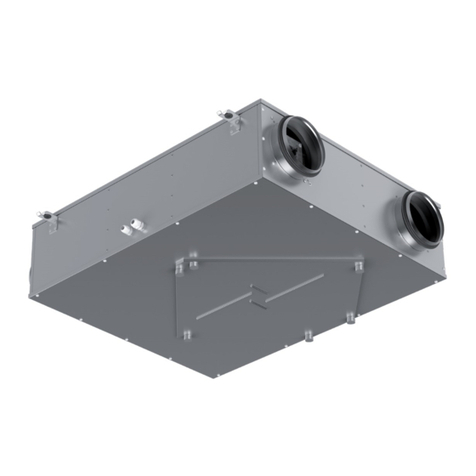
  9. Vents VUT 350 PE EC User manual

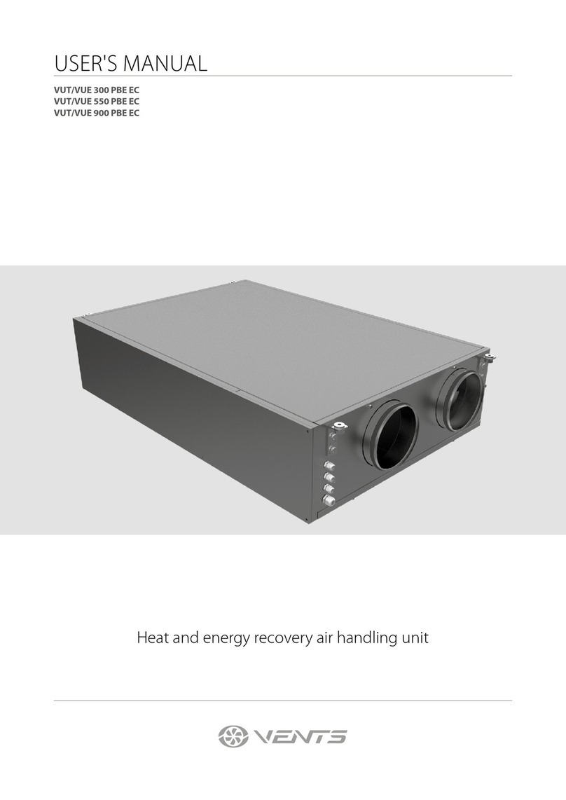
Vents VUT 350 PE EC User manual

Other manuals for VUT 350 PE EC

1

This manual suits for next models

2

Other Vents Air Handler manuals

Vents VUT 160 V EC User manual

Vents

Vents VUT 160 V EC User manual

Vents Micra 150 E User manual

Vents

Vents Micra 150 E User manual

Vents VUT2 250 P EC User manual

Vents

Vents VUT2 250 P EC User manual

Vents VUT 800 WH User manual

Vents

Vents VUT 800 WH User manual

Vents Micra 100 Wi-Fi User manual

Vents

Vents Micra 100 Wi-Fi User manual

Vents VUT 350 EH User manual

Vents

Vents VUT 350 EH User manual

Vents VUT 550 PBW EC User manual

Vents

Vents VUT 550 PBW EC User manual

Vents KOMFORT EC DBE 300 User manual

Vents

Vents KOMFORT EC DBE 300 User manual

Vents MPA W Series User manual

Vents

Vents MPA W Series User manual

Vents VUE 300 PBE EC User manual

Vents

Vents VUE 300 PBE EC User manual

Vents MICRA 100 User manual

Vents

Vents MICRA 100 User manual

Vents DVUT 300 PB EC User manual

Vents

Vents DVUT 300 PB EC User manual

Vents VUT 600 PW EC User manual

Vents

Vents VUT 600 PW EC User manual

Vents VUT 350 EH User manual

Vents

Vents VUT 350 EH User manual

Vents VUT 250 VB EC Series User manual

Vents

Vents VUT 250 VB EC Series User manual

Vents VUT 350 PE EC User manual

Vents

Vents VUT 350 PE EC User manual

Vents Micra 200 ERV WiFi User manual

Vents

Vents Micra 200 ERV WiFi User manual

Vents VUT 2000 PBW EC User manual

Vents

Vents VUT 2000 PBW EC User manual

Vents VUT 270 V5B EC A14 User manual

Vents

Vents VUT 270 V5B EC A14 User manual

Vents DVUT 1000 PB EC User manual

Vents

Vents DVUT 1000 PB EC User manual

Vents DVUT 300 HB User manual

Vents

Vents DVUT 300 HB User manual

Vents FB K2 UV User manual

Vents

Vents FB K2 UV User manual

Vents VUT 350 H User manual

Vents

Vents VUT 350 H User manual

Vents VUT R 400 EH EC A17 User manual

Vents

Vents VUT R 400 EH EC A17 User manual

Popular Air Handler manuals by other brands

Armstrong Air BCE7S Series installation instructions

Armstrong Air

Armstrong Air BCE7S Series installation instructions

Klimor EVO-S Operation and maintenance manual

Klimor

Klimor EVO-S Operation and maintenance manual

Salda SMARTY XP MOUNTING AND INSTALLATION INSTRUCTION

Salda

Salda SMARTY XP MOUNTING AND INSTALLATION INSTRUCTION

BLAUBERG KOMFORT Roto EC S400 user manual

BLAUBERG

BLAUBERG KOMFORT Roto EC S400 user manual

Trenton TPLP Series installation instructions

Trenton

Trenton TPLP Series installation instructions

Daikin DV PTC 14 Series installation instructions

Daikin

Daikin DV PTC 14 Series installation instructions

Haier HB2400VA1M20 Installation & operation manual

Haier

Haier HB2400VA1M20 Installation & operation manual

Webasto BlueCool A-Series operating instructions

Webasto

Webasto BlueCool A-Series operating instructions

RDZ DA 701 Technical installation manual

RDZ

RDZ DA 701 Technical installation manual

Carrier 39T Installation, Start-Up and Service Instructions

Carrier

Carrier 39T Installation, Start-Up and Service Instructions

Armstrong Air BCE5V Series installation instructions

Armstrong Air

Armstrong Air BCE5V Series installation instructions

Carrier 40MBDAQ Service manual

Carrier

Carrier 40MBDAQ Service manual

TemperZone Econex Pro OPA 1410RLTM4FPQD Installation & maintenance

TemperZone

TemperZone Econex Pro OPA 1410RLTM4FPQD Installation & maintenance

RDZ WHR 200 Technical installation manual

RDZ

RDZ WHR 200 Technical installation manual

AAON H3 Series Installation operation & maintenance

AAON

AAON H3 Series Installation operation & maintenance

Lennox VEOA042N432U Installation & operation instructions

Lennox

Lennox VEOA042N432U Installation & operation instructions

Kemper CleanAirTower operating manual

Kemper

Kemper CleanAirTower operating manual

Salda RIRS 400VE EKO 3.0 Technical manual

Salda

Salda RIRS 400VE EKO 3.0 Technical manual

manuals.online logo
manuals.online logoBrands
  • About & Mission
  • Contact us
  • Privacy Policy
  • Terms and Conditions

Copyright 2025 Manuals.Online. All Rights Reserved.

USER’S MANUAL
VUT 350 PE EC
VUT 600 PE EC
VUT 1000 PE EC
HEAT RECOVERY
AIR HANDLING UNIT
2VUT .. PE EC
CONTENTS
Safety requirements 3
Introduction 5
Use 5
Delivery set 5
Designation key 5
Technical parameters 5
Design and operating logic 7
Mounting and set-up 8
Condensate drain 9
Connection to power mains 11
Unit control 12
Maintenance 12
Troubleshooting 14
Storage and transportation rules 14
Manufacturer's warranty 15
Acceptance certicate 16
Seller's information 16
Mounting certicate 16
Warranty card 17
SAFETY REQUIREMENTS
• Please read the user’s manual carefully prior to installing and operating the unit.
• All user’s manual requirements as well as the provisions of all the applicable local and national construction, electrical, and
technical norms and standards must be observed when installing and operating the unit.
• The warnings contained in the user’s manual must be considered most seriously since they contain vital personal safety
information.
• Failure to follow the rules and safety precautions noted in this user’s manual may result in an injury or unit damage.
• After a careful reading of the manual, keep it for the entire service life of the unit.
• While transferring the unit control, the user’s manual must be turned over to the receiving operator.
UNIT INSTALLATION AND OPERATION SAFETY PRECAUTIONS
• Disconnect the unit from power mains prior
to any installation operations. • Unpack the unit with care.
• The unit must be grounded!
• While installing the unit, follow the safety
regulations specific to the use of electric
tools.
• Do not change the power cable length at
your own discretion. Do not bend the power
cable. Avoid damaging the power cable. Do
not put any foreign objects on the power
cable.
• Do not lay the power cable of the unit in
close proximity to heating equipment.
• Do not use damaged equipment or cables
when connecting the unit to power mains.
• Do not operate the unit outside the
temperature range stated in the user’s
manual. Do not operate the unit in
aggressive or explosive environments.
3
VUT .. PE EC
THE PRODUCT MUST BE DISPOSED SEPARATELY AT THE END OF ITS SERVICE LIFE.
DO NOT DISPOSE THE UNIT AS UNSORTED DOMESTIC WASTE.
• Do not touch the unit controls with wet
hands. Do not carry out the installation and
maintenance operations with wet hands.
• Do not wash the unit with water. Protect the
electric parts of the unit against ingress of
water.
• Do not allow children to operate the unit. • Disconnect the unit from power mains prior
to any technical maintenance.
• Do not store any explosive or highly
flammable substances in close proximity to
the unit.
• When the unit generates unusual sounds,
odour, or emits smoke, disconnect it from
power supply and contact the Seller.
• Do not open the unit during operation. • Do not direct the air flow produced by the
unit towards open flame or ignition sources.
• Do not block the air duct when the unit is
switched on.
• In case of continuous operation of the unit,
periodically check the security of mounting.
• Do not sit on the unit and avoid placing
foreign objects on it. • Use the unit only for its intended purpose.
4VUT .. PE EC
INTRODUCTION
This user’s manual includes technical description, operation, installation and mounting guidelines, technical data for the heat
recovery air handling unit VUT PE EC, hereinafter referred as the unit.
USE
Unit - 1 item
Control panel - 1 item
User’s manual for the air handling unit - 1 item
User’s manual for the control panel - 1 item
Packing box 1 item
Outdoor temperature sensor - 1 item.
DESIGNATION KEY
DELIVERY SET
Control panel
____ — PU SENS 01 with a sensor display
A7 — PU JK 01 with LCD display
Service side
L - left service side
R - right service side
Motor type
EC - electronically commutated motor
Heater type
E - electric heater
Unit type
VUT - heat recovery ventilation
Mounting option
P - suspended mounting
Air capacity [m3/h]
VUT ХХХ PE ЕС Х Х
THE UNIT SHOULD NOT BE OPERATED BY CHILDREN OR PERSONS WITH REDUCED
PHYSICAL, MENTAL, OR SENSORY CAPACITIES, OR THOSE WITHOUT
THE APPROPRIATE TRAINING.
THE UNIT MUST BE INSTALLED AND CONNECTED ONLY BY PROPERLY QUALIFIED
PERSONNEL AFTER THE APPROPRIATE BRIEFING.
THE CHOICE OF UNIT INSTALLATION LOCATION MUST PREVENT UNAUTHORIZED
ACCESS BY UNATTENDED CHILDREN.
The unit is designed to ensure continuous mechanical air exchange in houses, offices, hotels, cafés, conference halls, and other
utility and public spaces as well as to recover the heat energy contained in the air extracted from the premises to warm up the
filtered stream of supply air.
The unit is not intended for organizing ventilation in swimming pools, saunas, greenhouses, summer gardens, and other spaces
with high humidity.
Due to the ability to save heating energy by means of energy recovery, the unit is an important element of energy-efficient
premises.
The unit is a component part and is not designed for stand-alone operation.
It is rated for continuous operation.
Transported air must not contain any flammable or explosive mixtures, evaporation of chemicals, sticky substances, fibrous
materials, coarse dust, soot and oil particles or environments favourable for the formation of hazardous substances (toxic
substances, dust, pathogenic germs).
Relative humidity of transported air must not exceed 80 % at an ambient temperature of +20 °C.
5
VUT .. PE EC
TECHNICAL PARAMETERS
UNIT TECHNICAL DATA
Voltage, 50/60 Hz [V] 1 ~ 230
Max. fan power [W ] 200 270 400
Max. fan current [A] 1,62 1,6 2,26
Electric heater power [kW] 1,5 2 3,3
Electric heater current [A] 6,5 8,7 14,3
Total unit power [kW] 1,7 2,27 3,7
Total unit current [A] 8,12 10,3 16,56
Air capacity [m3/h] 400 700 1100
Rotation speed [min -1] 3560 3060 2780
Noise level, 3 m [dBA] 48 53 52
Transported air temperature [°С] -25 ... +40 -25 ... +60
Casing material Aluzinc
Insulation 20 mm mineral wool
Filter: extract G4
supply G4 (F7)
Connecting air duct dia. [mm] Ø160 (Ø150)* Ø200 Ø250
Weight [kg] 67 75 95
Heat recovery efficiency up to 90%
Heat exchanger type Counter-flow
Heat exchanger material Polystyrene
* in case of using a Ø 160 to Ø 150 mm air duct. Not included into the delivery set.
The unit is designed for indoor application with the ambient temperature ranging from +1 °C up to +40 °C and relative humidity
up to 80 %.
In order to prevent condensation on the internal walls of the units, it is necessary that the surface temperature of the casing is 2-3
°C higher than the dew point temperature of the transported air.
The unit is rated as a Class I electrical appliance.
Hazardous parts access and water ingress protection rating:
• IP22 for the unit connected to the air ducts
• IP44 for the unit motors
The unit design is constantly being improved, thus some models may be slightly different from those described in this manual.
6VUT .. PE EC
OVERALL DIMENSIONS OF THE UNIT, MM
Modell Ø D 1 2  4 5 1 LL1
VUT 350 PE EC 160 485 415 554 135,5 214 577 281 152 1238 1291
VUT 600 PE EC 200 827 713 723 294 345 920 280 120 1238 1291
VUT 1000 PE EC 250 1351 608 522 431 655 1444 318 143 1349 1402
L1
ø d
Ø D
B1B1 H
H1
L
B1B2
B3 B4
B
B5
Ø D
B1
H
H1
L
L1
B2
B5
B3 B4
ø d
VUT 600 PE EC, VUT 1000 PE EC
VUT 350 PE EC
7
VUT .. PE EC
DESIGN AND OPERATING LOGIC
The unit operates as follows:
Warm stale extract air from the room ows through the air ducts to the unit, where it is ltered, then air ows through the heat
exchanger and is exhausted outside by the extract fan through the air ducts.
Clean cold air from outside is moved by the supply fan to the unit, where from it is directed to the supply lter. Then ltered air ows
through the heat exchanger and moves to the room through the air ducts.
Heat energy of warm extract air is transferred to clean intake fresh air from outside and warms it up. Heat recovery minimizes thermal
energy losses, energy demand and operating costs for air heating accordingly.
The unit is equipped with a detachable service panel for repair works and preventive maintenance and a cover enabling access to
the control system components.
SUPPLY AIR
EXTRACT AIR
INTAKE AIR
EXHAUST AIR
The basic unit delivery set includes a remote control panel for connection to the control system inside the unit casing.
The unit comprises a supply and an extract centrifugal single-inlet fan with forward curved blades and maintenance-free EC motors
with external rotor and built-in overheat protection, a plate counterow heat exchanger and an electric heater.
The supply G4 lter cleans supply air ow and prevents contamination of the unit parts. The extract G4 lter prevents contamination
of the unit components.
Some condensate may be generated during heat recovery. The condensed uid is collected in the drain pan and is removed from the
unit through the drain hoses.
UNIT DESIGN BASED
on VUT 350 PE EC
EXTRACT FAN
SUPPLY FILTER
EXTRACT FILTER
BYPASS
SUPPLY FAN
DRAIN PAN
ELECTRIC HEATER
CONTROL UNIT
CONTROL PANEL
HEAT EXCHANGER
DIFFERENTIAL
PRESSURE SWITCH
DIFFERENTIAL
PRESSURE SWITCH
UNIT OPERATING LOGIC
based on VUT 600 PE EC unit example
8VUT .. PE EC
MOUNTING AND STARTUP
UNIT MOUNTING
The unit is designed for suspended mounting by means of the threaded rod xed in the threaded dowel pin.
washer
wut
vibration-absorbing
rubber
nut and
lock-nut
Example
MINIMUM ACCESS TO THE UNIT
While mounting the unit provide enough space for its servicing and maintenance.
To attain the best performance of the unit and to minimise turbulence-induced air pressure losses while mounting connect a straight
air duct section on both sides of the unit.
Minimum straight air duct length:
• equal to 1 air duct diameter on intake side.
• equal to 3 air duct diameters on outlet side.
If the air ducts are not connected or the connected air ducts are too short, protect the unit parts from ingress of foreign objects
by covering the spigots with a protecting grille or other protecting device with mesh width not more than 12.5 mm to prevent
uncontrollable access to the fans.
MINIMUM REQUIRED ACCESS TO THE UNIT
UNIT CONTROLS LOCATION
Modell VUT 350 PE  VUT 600 PE  VUT 1000 PE 
min А, mm 500 850 800
min A depends on the lter
VUT 350 PE EC - 441 mm;
VUT 600 PE EC - 784 mm;
VUT 1000 PE EC - 650 mm (less than VUT 600 PE EC).
9
VUT .. PE EC
The unit is available with the service side located on the left and on the right of the unit to facilitate mounting and provide minimum
service access.
UNIT MODIFICATIONS
SUPPLY AIR
EXTRACT AIR
EXHAUST AIR
INTAKE AIR
SUPPLY AIR
EXTRACT AIR
EXHAUST AIR
INTAKE AIR
RIGHT-HAND MODIFICATION
(TOP VIEW)
LEFT-HAND MODIFICATION
(TOP VIEW)
SERVICE SIDE
SERVICE SIDE
Safety precautions
The unit is designed for mounting on a rigid and stable structure.
The unit is mounted with anchor bolts. Make sure that a mounting construction has sucient load capacity matching the unit weight.
Otherwise reinforce an installation place by beams, etc.
If the threaded bolts used for the unit mounting are too short, the unit can generate abnormal noise and resonate with the ceiling. The
suspended bolts must be long enough to prevent resonating.
If the unit connection place to the spiral seam duct is supposed to be the source of abnormal noise, replace the spiral seam air duct with
the exible one. Optionally the exible connectors may be used to prevent resonating.
CONDENSATE DRAINAGE
The condensate drain pan in the heat recovery section is equipped with two hoses for extracting the condensed uid outside the
unit. Connect the pipe, U-trap (not included in delivery package) and sewage collection system with metal, plastic or rubber connecting
pipes. The pipe slope downwards must be at least 3°. Fill up the system with water before connecting the unit to the power mains! The
U-trap must always be lled with water during the unit operation. Make sure that the water ows freely into the sewage collection
system or otherwise condensed water may build up in the unit during the heat exchanger operation and cause equipment failure and
condensed water outow into the premises.
The condensate drainage system is designed for normal operation in premises with air temperatures above 0 °C. If the expected
ambient air temperatures are below 0 °C the condensate drainage system must be equipped with heat insulation and pre-heating
facilities.
min 3 °
DRAIN PIPE
SEWAGE SYSTEM
PIPE
PIPE
U-TRAP
10 VUT .. PE EC
13
24
OUTDOOR TEMPERATURE SENSOR INSTALLATION AND CONNECTION
The air handling unit is equipped with an outdoor temperature sensor.
Mounting of the outdoor temperature sensor:
1. Remove two screws from the sensor cover.
2. Take o the cover from the sensor.
3. Install the sensor on the outside wall. The wall must not be exposed to direct sunlight.
4. Install the sensor cover back.
5. Connect the sensor to the terminal block X1 in compliance with the external wiring diagram at page 12.
DUCT HUMIDITY SENSOR INSTALLATION AND CONNECTION
HV1 duct humidity sensor is a special accessory that is not included into the delivery set. To install the sensor connect the humidity
sensor socket connector to the socket connector inside the unit. Then x the sensor with the clamp and the holder in the extract air duct
upstream of the heat exchanger.
1. 2. 3.
Duct humidity sensor installation place
VUT 350 PE EC
Duct humidity sensor installation place
VUT 600(1000) PE EC
Duct humidity sensor connection