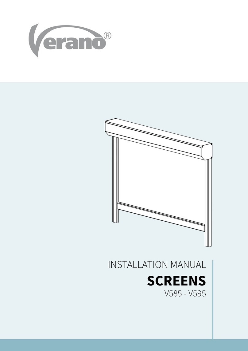
Verano Ritzscreen V540 User manual

INSTALLATION MANUAL
RITZSCREEN®
V540
V599 - V599R
V599 L - V599 XL

1788-190913EN
1
Subject to misprints, errors and technical modifications.
INSTALLATION MANUAL
RITZSCREEN® V540 - V599 - V599R - V599L - V599 XL
Content
1. Screen cover with fabric and motor
2. Side guides
a. backprole
b. insert provided with neoprene (Ritz guide)
c. frontprole
3. Mounting set
4. Control
a. electrical: switchandplug
b. remotecontrol: remotecontrolandplug
Necessary tools
• Drillingmachine
• Metaldrill6/10mm
• Masonrydrill6/10mm
• Crosshead screwdriver
• Hex key
• Tapeline
• Level
• Pencil
Incaseofelectricalcontrol:
• Nippers
• Flatheadscrewdriver
1
2a
2b
2c

1788-190913EN
2
Subject to misprints, errors and technical modifications.
INSTALLATION MANUAL
RITZSCREEN® V540 - V599 - V599R - V599L - V599 XL
Specications Ritzscreens®
Ritzscreen® V540
42
95
42
95
95
95
45
27
65
40
42
42
section bottom bar (O)
section cover (K), bottom bar (O) and guide (G)
section guide (G) right
MaximumorderingsizeV540=3000mm
Attention!TheRitzscreen®V540isdeliveredwithguides
providedwithpredrilledmountingholesinthebackprole.
Onlyuseatcounter-sunkscrews.
Measurements in mm
Ritzscreen® V599 Ritzscreen® V599R
105
51
101
96
51
101
45
27
65
40
51
33
35
1820
section bottom bar (O)
section cover (K), bottom bar (O) and guide (G)
section guide (G) right
maximumorderingheightV599=3500mm
maximumorderingheightV599R=3100mm

1788-190913EN
3
Subject to misprints, errors and technical modifications.
INSTALLATION MANUAL
RITZSCREEN® V540 - V599 - V599R - V599L - V599 XL
45
27
65
40
51
33
35
1820
Specications Ritzscreens®
Ritzscreen® V599 XL
section cover (K), bottom bar (O) and guide (G)
section bottom bar (O)
section guide (G) right
maximumorderingheightV599XL=6000mm
Measurements in mm
Ritzscreen® V599 L
125
130
42
45
27
65
40
42
42
maximumorderingheightV599L=5000mm
Attention!TheRitzscreen®V599Lisdeliveredwithguides
providedwithpredrilledmountingholesinthebackprole.
Onlyuseatcounter-sunkscrews.
155
51
151

1788-190913EN
4
Subject to misprints, errors and technical modifications.
INSTALLATION MANUAL
RITZSCREEN® V540 - V599 - V599R - V599L - V599 XL
Important before mounting
Be careful for damages
Don’t use a knife or any other sharp object when opening the packing. This may cause damage to the content of the
package.Putthecontentofthepackageonasosurface.Becarefulwhendrilling,fallingdrillcuttingscancausedamages.
Checkifthewindowframeorfaçadeisatandsmooth.
General warning
MountingtheVerano®productyourselfisatyourownrisk.Onlyusethisinstructionasatoolandforthemountingofthis
specicVerano®product.Ifyoucannotmounttheproductyourself,youcanalwaysoptforprofessionalmounting.The
mountingteamofVerano®ispleasedtohelpyou.

1788-190913EN
5
Subject to misprints, errors and technical modifications.
INSTALLATION MANUAL
RITZSCREEN® V540 - V599 - V599R - V599L - V599 XL
> 15 cm
Y
± 50 cm
> 2 cm
in de dag
op de dag
± 50 cm
Y=guideheight
Screws per guide
Y<125cm: 2x
Y=125-225cm: 3x
Y>225-285cm: 4x
Theguidesconsistofthreeparts:
a. backprole
b. insert provided with neoprene (Ritz guide)
c. frontprole
These three parts are pushed together in the package. Separate the parts before mounting.
1.1 Marking the mounting holes in the back prole (only for V599 – V599R – V599 XL)
Therearenoholesinthebackprole(a)oftheguides.Theamountofholesandtheplacingoftheholesdependsonthe
subsurfaceandthesizeofthescreen.Thesubsurfaceofthewindowframecanbemadeofwood,metalorconcrete.
1. Placethelebackprolevertically,atthecorrectheight,againstthefaçadeorthewindowframe.Viewgure1.1.
2. Markthemountingholesontheguide.Thechoiceforinside mounting or outside mounting determines how the back
proleneedstobemounted.Whenmountedonthewallyouneedtotakecarethatthemountingholesareinthe
middleofthestoneandnotintheseamofthestone!
Therstholeattheattachmentpointonthescreencoverneedstobedrilledatleast15cmfromtheedge.Thisspace
shouldbekeptclearforthecoversupport.Thelowestholeneedstobedrilledatleast2cmfromthebottom.
3. Placetherightbackproleatthecorrectheightandwidthagainstthewallandmarkthemountingholesinthesame
way.
Attention! Theleandrightbackproleneedtobelevelledexactly.Useashelforleveltocheckthis.
1. Instruction placing the screen (outside)
g. 1.1 Marking the mounting holes
Outside Mount
Inside Mount

1788-190913EN
6
Subject to misprints, errors and technical modifications.
INSTALLATION MANUAL
RITZSCREEN® V540 - V599 - V599R - V599L - V599 XL
in de dag
12
Y
> 100 mm
< 1800 mm
> 100 mm
10 mm
6 mm
op de dag
6 mm 10 mm
1.2 Drilling the mounting holes in the back prole
Thescrewholesneedtobeduplicated.Theproleisprovidedwithadrilllineasanaidtoolforthedrilling.Viewgure1.2.
1. Drillaholeof6mmthroughbothlayersinthebackproleoftheguide.
2. Aerthat,drilltheholewitha10mmdrillsothatthescrewdrivertsthrough.
g. 1.2 Drilling mounting holes
g. 1.3 Mounting the back guide
1.3 Mounting the guide
1. Placethebackproleoftheguidesbackagainstthefaçadeorthewindowframe.Makesurethattheguidesare
perpendicularwiththewall.Youcanmarkthedrillholesatthewallorthewindowframeonthebaseoftheholesinthe
guides.
2. Drillthenalholes.Mindthesizeofthescrewsandplugsthatyouaregoingtouse.
in de dagop de dag
3. Screwtheguidestight.Tightenthetopscrewsloosely,notcompletelyxed.Thiswaytheguidescanbebrought
forwardwhenplacingthescreencover.
Outside Mount
Inside Mount
Outside Mount Inside Mount

1788-190913EN
7
Subject to misprints, errors and technical modifications.
INSTALLATION MANUAL
RITZSCREEN® V540 - V599 - V599R - V599L - V599 XL
in de dagop de dag
g. 1.5 Correct mounting of the Ritzscreen® V540/V599 L
g. 1.4 Mounting the back guide of the Ritzscreen® V540/V599 L
g. 1.6 Incorrect mounting of the Ritzscreen® V540/V599 L
1.4 Mounting the V540/V599 L guide
TheRitzscreen®V540andV599Lissuppliedwithguideswithpredrilledmountingholesinthebackprole.Thisoccursin
axedpattern.Atscreenswithatotalheightupto1800mm,theguidesareprovidedwithtwoholes:1hole100mmfrom
thetopand1hole100mmfromthebottom.Atscreenswithatotalheightofmorethan1800mm,theguidesareprovided
with threeholes:1hole100mmfromthetop,1hole100mmfromthebottomand1holeinthemiddle.
Attention!Byincorrectmountingorwhenusingthewrongscrews,theinsertprovidedwithneoprenecannotfreelymove
intheguide.Whenusingthescreen,theinsertorguideispulledcrookedintheprole.Thiscancausedamagetothe
system.Thegurebelowshowswhatgoeswrongwhen(a)thescrewisnotplacedfarenoughintheguideand(b)ascrew
with a round head is used.
3. Screwtheguidestight.Tightenthetopscrewsloosely,notcompletelyxed.Thiswaytheguidescanbebrought
forwardwhenplacingthescreencover.
2. Drilltheholes.Mindthesizeofthescrewsandplugsthatyouaregoingtouse.Onlyusescrewswithaathead that can
be mounted countersunkwhenmounting.Thesurfaceareaneedstobeentirelyplane.
1. Placethebackproleoftheguidesagainstthefaçade
or the window frame as described in paragraph 1.1.
Makesurethattheguidesareperpendicularandequal
tothewall.Themarkingofthedrillholesonthewallor
thewindowframecanbemadeonthebaseoftheholes
in the guides.
Outside Mount Inside Mount
1788-190913EN
8
Subject to misprints, errors and technical modifications.
INSTALLATION MANUAL
RITZSCREEN® V540 - V599 - V599R - V599L - V599 XL
1.6 Placing the screen cover on the guides
1. Lithecoverwithtwopeople.
2. Performtheelectricalcordthroughthedrilledholetotheinside.
3. Slidethecapsupports,thatextendunderthescreencover,inthebackproleofthesideguides.Beextracarefulwhile
tdoingthis.Thecapsupportsareveryvulnerable.
4. Checkifthescreencoverrunslevelled.
5. Screwthetopscrewsxedintheguides.
6. Thecapisnowmountedtightenoughandxingisnotnecessary.
g. 1.7 Placing the screen cover
1.5 Hole for control
1. Accuratemarktheinsidetransitholeforthecontrolcord.Thisholeneedstobeatexactlythesameheightasthepoint
wherethecontrolcordcomesoutofthescreen!
2. Drilltheholeforthewalltransitwitha10mmdrill.
3. Checkbeforedrillingiftherearenopipesorotherlinesinthewall!
4. Alwaysuseashelfontheinsideofthehouse,sothatthestuccocannotbedamaged.
Extra attention with a low gutter or roof edge!
Whenascreenneedstobemountedunderalowgutteror
roofedge,itisnecessarytoplacethescreencoveronthe
guides before the back guides are being screwed to the
wall.
Beextracarefulwhenmounting.Thecapsupportsarevery
vulnerable!Topreventbrokencapsupports,alwaysli
thescreenwithtwopeopleattheattachmentpointofthe
screen cover to the side guides.

1788-190913EN
9
Subject to misprints, errors and technical modifications.
INSTALLATION MANUAL
RITZSCREEN® V540 - V599 - V599R - V599L - V599 XL
1.8 Finish outside mounting
Lutetheupsideandthesidesofthecoverinordertopreventwaterfromrunningthroughthecabletotheinside.
Theuseoftransparentluteisadvised.
1.7 Sliding the zipper into the guide
1. Placetheinsert(Ritzguide)(b),withtheV-proleup,alittleobliqueinthebackprole(a).
2. SlidetheedgeofthezipperfromthetopintheV-proleoftheRitzguide(b).Makesurethatittswellinthegap!
PushtheRitzguide(b)thenallthewayupintothebackprole.
3. Mountthefrontprole(c)onthebackprole(a)withtheincludedscrews.
4. Themountingofthescreenisnowalmostnished.
12
34
g. 1.8 Mounting the guide
b
a
b
c

1788-190913EN
10
Subject to misprints, errors and technical modifications.
INSTALLATION MANUAL
RITZSCREEN® V540 - V599 - V599R - V599L - V599 XL
1. Determine the position of the
switch inside the house and mark
twoholesonthewall.
2. Drilltheholeswitha6mmdrill.
3. Opentheswitch,usingaat
screwdriver.
4. Placetheplugsandmountthe
switch with two countersunk
screws.
Makesurethatthepoweriso
andwithouttension!
Ø6
230 V
2. Instruction placing the electrical control (inside)
Optioneel
230 V
Optional

1788-190913EN
11
Subject to misprints, errors and technical modifications.
INSTALLATION MANUAL
RITZSCREEN® V540 - V599 - V599R - V599L - V599 XL
5. Connectthe4-wiredcordofthemotorandthe3-wiredcordandplugfollowingtheschemebelow.
Checkaninstallerwhenneeded.
yellow/green
blue
brown
yellow/green
blue black
brown
brown
yellow/green
blue
brown
yellow/green
blue
black
brown
brown
yellow/green
blue
brown
yellow/green
blue black
brown
brown
yellow/green
blue
brown
yellow/green
blue
black
brown
brown
Motor le (seen from the outside) Motor right (seen from the outside)
Optioneel
230 V
6. Mounttheswitch.
Atasituationwithawirelessremote
control,the3-wiredcordcandirectly
be connected to the socket.
7. Inserttheplugintothesocket
and turn the power on.
The screen is now ready to be
controlled.
* ViewtheincludedSOMFYinstructionforsettingtheremotecontrol.
*Optional
This manual suits for next models
4
Other Verano Projection Screen manuals
Popular Projection Screen manuals by other brands

Stewart Filmscreen
Stewart Filmscreen C installation instructions

Eclipse
Eclipse E-Zip installation instructions

Atrium
Atrium Euroscreen Frame Vision Light quick start guide

AccuScreens
AccuScreens ELECTRIC SCREEN operating instructions

displayit
displayit exhibitline quick start guide

Draper
Draper Ambassador 220V Installation & operating instructions