•The product was developed, manufactured and inspected
according to the basic safety requirements of EC Guidelines
and state-of-the-art technology.
•The instrument is designed for use in grounded vehicles and
machines as well as in pleasure boats, including non-
classified commercial shipping.
•Use our product only as intended. Use of the product for
reasons other than its intended use may lead to personal
injury, property damage or environmental damage. Before
installation, check the vehicle documentation for vehicle
type and any possible special features!
•Use the assembly plan to learn the location of the
fuel/hydraulic/compressed air and electrical lines!
•Note possible modifications to the vehicle, which must be
considered during installation!
•To prevent personal injury, property damage or
environmental damage, basic knowledge of motor
vehicle/shipbuilding electronics and mechanics is required.
•Make sure that the engine cannot start unintentionally
during installation!
•Modifications or manipulations to veratron products can
affect safety. Consequently, you may not modify or
manipulate the product!
•When removing/installing seats, covers, etc., ensure that
lines are not damaged, and plug-in connections are not
loosened!
•Note all data from other installed instruments with volatile
electronic memories.
SAFETY DURING INSTALLATION
•During installation, ensure that the product’s components
do not affect or limit vehicle functions. Avoid damaging
these components!
•Only install undamaged parts in a vehicle!
•During installation, ensure that the product does not impair
the field of vision and that it cannot impact the driver’s or
passenger’s head!
•A specialized technician should install the product. If you
install the product yourself, wear appropriate work
clothing. Do not wear loose clothing, as it may get caught in
moving parts. Protect long hair with a hair net.
•When working on the on-board electronics, do not wear
metallic or conductive jewelry such as necklaces, bracelets,
rings, etc.
•If work on a running engine is required, exercise extreme
caution. Wear only appropriate work clothing as you are at
risk of personal injury, resulting from being crushed or
burned.
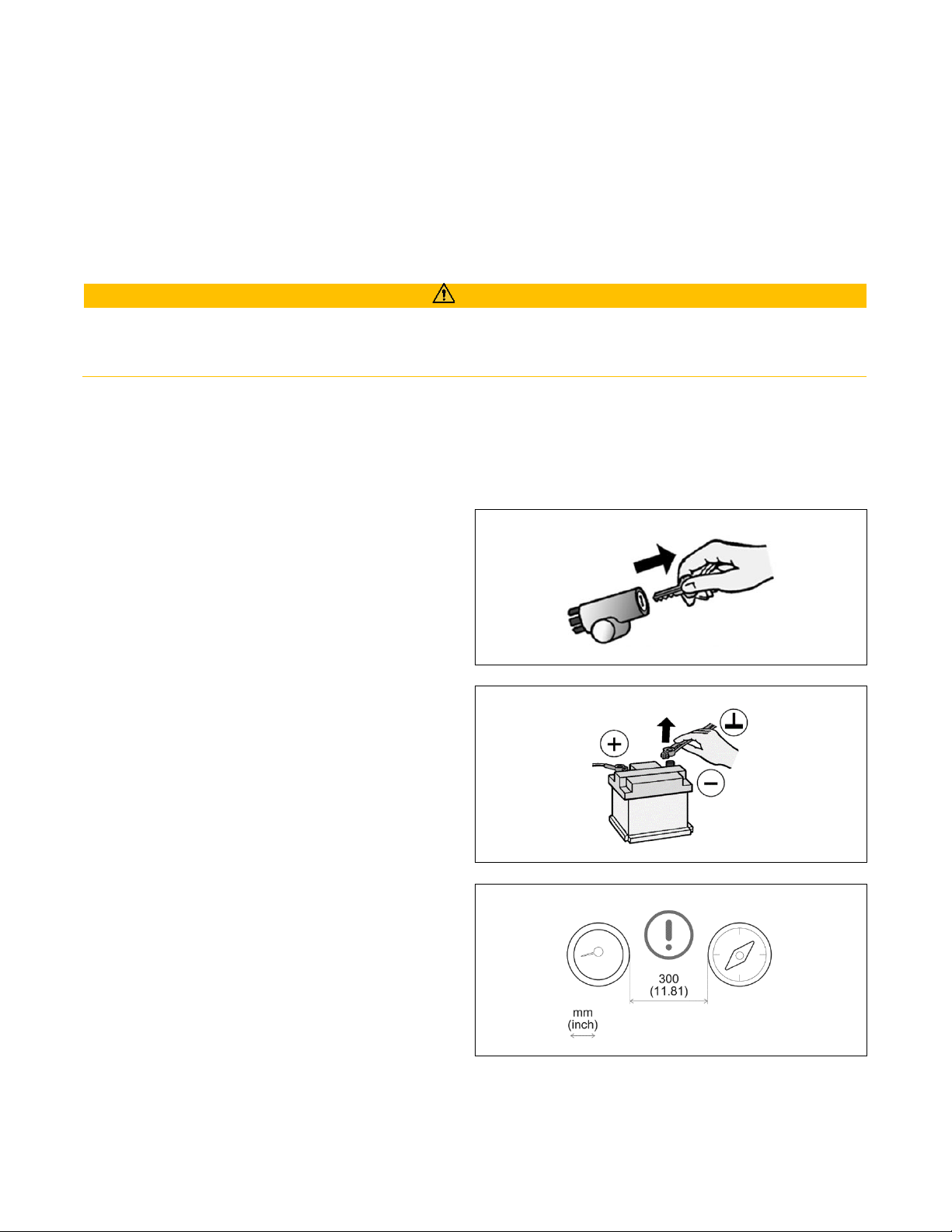
•Before beginning, disconnect the negative terminal on the
battery, otherwise you risk a short circuit. If the vehicle is
supplied by auxiliary batteries, you must also disconnect
•the negative terminals on these batteries! Short circuits can
cause fires, battery explosions and damages to other
electronic systems. Please note that when you disconnect
the battery, all volatile electronic memories lose their input
values and must be reprogrammed.
•If working on gasoline boat motors, let the motor
compartment fan run before beginning work.
•Pay attention to how lines and cable harnesses are laid so
that you do not drill or saw through them!
•Do not install the product in the mechanical and electrical
airbag area!
•Do not drill holes or ports in load-bearing or stabilizing stays
or tie bars!
•When working underneath the vehicle, secure it according
to the specifications from the vehicle manufacturer.
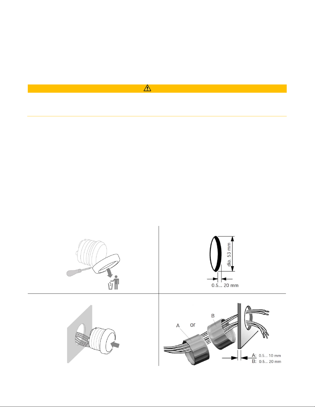
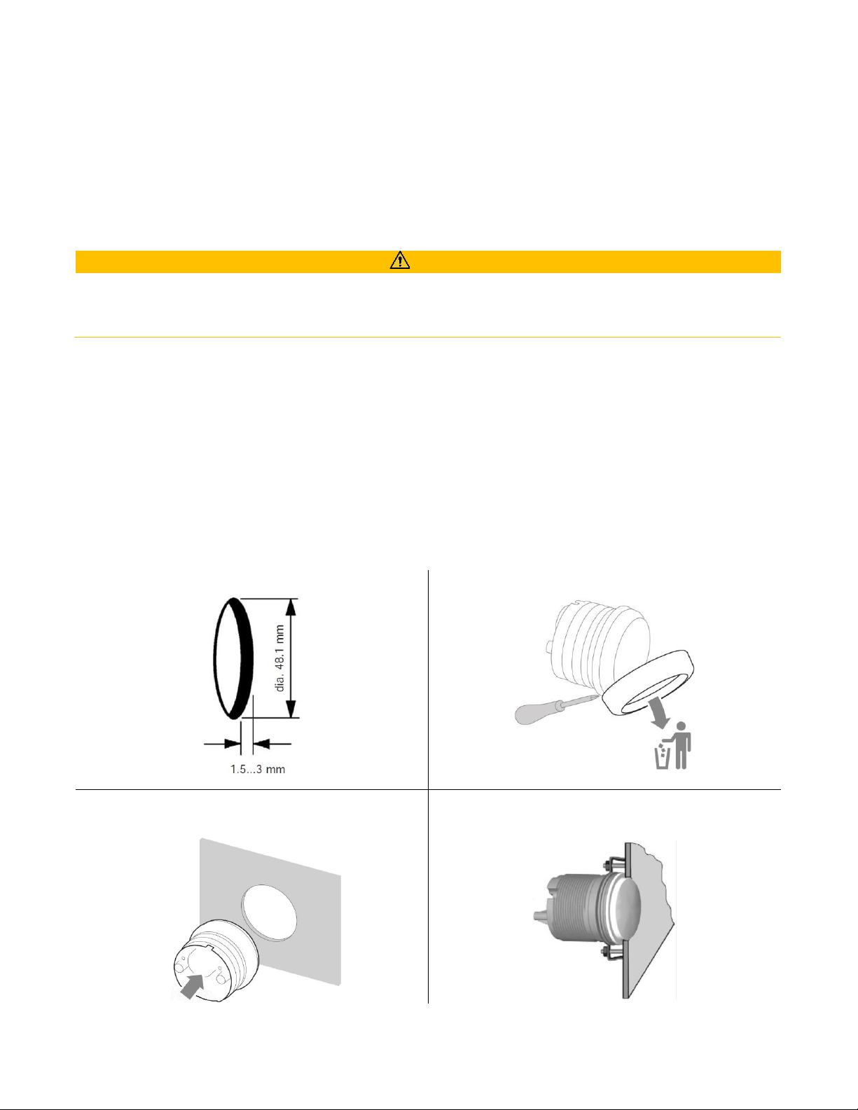
•Note the necessary clearance behind the drill hole or port
at the installation location. Required mounting depth: 65
mm.
• Drill small ports; enlarge and complete them, if necessary,
using taper milling tools, saber saws, keyhole saws or files
Deburr edges. Follow the safety instructions of the tool
manufacturer.
•Use only insulated tools if work is necessary on live parts.
•Use only the multimeter or diode test lamps provided, to
measure voltages and currents in the vehicle/machine or
boat. Use of conventional test lamps can cause damage to
control units or other electronic systems.