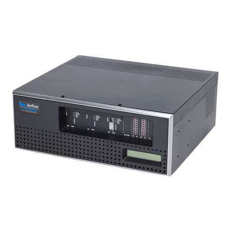
VeriFone Commander Manual

Hardware Installation Guide
CommanderTM Site Controller
P/N DOC149-003-01-R
Rev. A02


Commander™ Site Controller Hardware Installation Guide
February 6, 2013
VeriFone®, Inc.
2099 Gateway Place
Suite 600
San Jose, CA 95110
Telephone: 408-232-7800
http://www.verifone.com
Printed in the United States of America.
© 2013 by VeriFone, Inc.
No part of this publication covered by the copyrights herein may be reproduced
or copied in any form or by any means — graphic, electronic, or mechanical,
including photocopying, taping, or information storage and retrieval systems —
without written permission of the publisher.
The contents of this document and all features and specifications are subject to
change without notice. The information contained herein does not represent a
commitment on the part of VeriFone, Inc.
Publications are not stocked at the address given above. Requests for VeriFone
publications should be made to your VeriFone representative.
VeriFone, the VeriFone logo, and Ruby SuperSystem are registered trademarks
of VeriFone, Inc. Sapphire, Topaz, HPV-20, Ruby Manager, Everest, EASY ID,
Electronic Journal On-site, and Ruby Card are trademarks of VeriFone, Inc. in
the U.S. and/or other countries. All other trademarks or brand names are the
properties of their respective holders.

Battery Charging Notification
The unit should be powered up for at least 24 hours prior to initial
application download. This is to prevent loss of data and to ensure
that the battery pack is fully charged.
Important Information
Changes or modifications not expressly approved by VeriFone, Inc.
could void the user’s authority to operate this equipment.
This equipment is not intended to be repaired by the user.

Commander Site Controller Hardware Installation Guide i
Contents
1. Introduction
Choosing a Location . . . . . . . . . . . . . . . . 3
Unpacking Commander Site Controller. . . . 4
System Requirements . . . . . . . . . . . . . . . 5
Cables. . . . . . . . . . . . . . . . . . . . . . 5
Uninterruptible Power Supply . . . . . . 5
2. Commander Site Controller Diagrams
Front Panel . . . . . . . . . . . . . . . . . . . . . 7
CPU A Indicators and Controls . . . . . . 8
CPU A Device Port LEDs (RX/TX) . . . . 9
Rear Panel . . . . . . . . . . . . . . . . . . . . . 10
3. Service and Cleaning
Service . . . . . . . . . . . . . . . . . . . . . . . 11
Battery . . . . . . . . . . . . . . . . . . . . 11
Modem . . . . . . . . . . . . . . . . . . . . 11
Cleaning . . . . . . . . . . . . . . . . . . . . . . 12
4. Specifications and Parts
Commander Site Controller Specifications 13
Memory . . . . . . . . . . . . . . . . . . . . 13
Dimensions/Weight . . . . . . . . . . . . 13
Certifications and Environmentals . . 13
Parts List . . . . . . . . . . . . . . . . . . . . . . 14
Included Parts List. . . . . . . . . . . . . 14
Optional Parts List. . . . . . . . . . . . . 14

ii Commander Site Controller Hardware Installation Guide

Commander Site Controller Hardware Installation Guide 1
1 INTRODUCTION
The Commander™ Site Controller is a high-powered server that
increases the capacity and functionality of VeriFone’s ethernet
capable Point of Sale (POS) workstations by extending the processing
and communications bandwidth for managing peripherals.
Future needs are designed into the hardware to provide support for
additional serial ports and CPU boards along with additional fan and/
or power connection that may be needed as a result. Use of these
expansion capabilities will be determined by VeriFone.
System peripherals, such as fuel dispensers, dispenser card readers
(DCRs), and car wash controllers connect directly to the Commander
Site Controller.
Commander Console provides additional functionality with four
separate software modules: Journal Browser, Configuration Client
(for browser-based configuration), Transaction Manager, and Report
Navigator.
Figure 1: Command Site Controller and Workstations
Workstation
Workstation
SS
s
Commander Site Controller

2Commander Site Controller Hardware Installation Guide
The Commander Site Controller contains the functionality of a V950™
to perform on-site maintenance operations such as backups,
upgrades, restores, and reversions to previous software versions.
The addition of a router allows the Commander Site Controller, with
the functionality of the V950, to:
■Receive configurations remotely using available Internet
protocols and tools, including a Web browser interface.
■Connect with VeriFone Technical Support Center computers
for software downloads and diagnostics.

Commander Site Controller Hardware Installation Guide 3
Choosing a Location
Many sites place the Commander Site Controller under the counter or
in the back office.
The Commander Site Controller may be mounted on a wall or under a
counter using the brackets designed specifically for it. See the
optional Commander Site Controller Bracket Kit for complete
mounting instructions. When deciding where to place the
Commander Site Controller, make sure that the location meets the
following requirements:
■Power: 120 Volts AC, 60 Hz, 3 Amps
■Temperature:
–Operating: 32 to 104° F (0 to 40° C)
–Non-operating: -40 to 158° F (-40 to 70° C)
■Humidity: 15 to 95% relative humidity at 40° C with no
condensation
Avoid locations with the following characteristics:
Warning: To reduce the risk of fire, do not place the Commander
Site Controller near objects that produce excessive
heat.
■Direct Sunlight
■Moisture
■Excessive dust
■Electrical “noise” or devices that cause excessive voltage
variations, such as air conditioners, fans, or high frequency
security systems.

4Commander Site Controller Hardware Installation Guide
Unpacking Commander Site Controller
Carefully inspect the Commander Site Controller shipping carton and
its contents for any damage that may have occurred during shipment.
If an item appears damaged, immediately file a claim with the
shipping company or carrier, and notify your VeriFone representative.
Warning: Never use damaged equipment. A shock or fire hazard
may exist if equipment is energized in a damaged
condition.
Remove the following items from the shipping carton:
■Commander Site Controller
■Power cord
■Software licenses
■Commander Site Controller Hardware Installation Guide
Remove any protective plastic wrapping from the items and place
them on a table or countertop. Check to make sure that you have all
the parts listed above before you begin. Contact the VeriFone
Technical Support Center if you are missing any of the items.
Note: Keep the shipping carton and any packing material in case
it is necessary to move the Commander Site Controller
from one location to another, or to return the equipment
for service.

Commander Site Controller Hardware Installation Guide 5
System Requirements
This section contains information about the cables and
uninterruptible power supply requirements for the Commander Site
Controller.
Note: The Commander Site Controller must be installed by a
VeriFone Authorized Service Contractor (VASC).
Cables
System-wide devices connect directly to the Commander Site
Controller.
The following are examples of devices that connect directly to the
Commander Site Controller:
■Tank Level Sensor
■Car Wash Controller
The standard cables required for installing Commander Site
Controller are as follows:
■RS-232 cable (P/N 13836-xx) between peripherals (such as car
wash controller or tank level sensor), to the Commander Site
Controller.
Note: The Commander Site Controller is designed to support up
to 64 DCRs, and allows as many as eight separate
connections.
Uninterruptible Power Supply
VeriFone strongly recommends that you connect the Commander Site
Controller to an uninterruptible power supply (UPS) with power
conditioning and a rating of 400VA or greater.

6Commander Site Controller Hardware Installation Guide

Commander Site Controller Hardware Installation Guide 7
2 COMMANDER SITE CONTROLLER DIAGRAMS
Front Panel
■System Status Display — The backlit, rectangular display on
the front panel of the Commander Site Controller
■CPU A Indicators and Controls — The indicators and controls
in this section of the front panel are specific to CPU A. A
detailed description follows in the next section.
■CPU A Device Port LEDs (RX/TX) — Displays activity for
devices connected to serial ports of CPU A
Figure 2: Commander Site Controller - Front Panel
System
CPU A Indicators and Controls
CPU A Device
Port LEDs (RX/TX)
Status Display

8Commander Site Controller Hardware Installation Guide
CPU A Indicators and Controls
Figure 3: Indicators and Controls for CPU A
■Reset Switch — For emergency use only and should never be
touched unless instructed by the VeriFone Technical Support
Center.
■Service Console Port — This port is for use by a VeriFone
Authorized Service Contractor. It connects the PC/Laptop to
the Commander Site Controller. The connection
communicates at 19200 bps 8N1. It is used to install software
and provides access to a serial diagnostic connection and
boot-up functions.
■Switch Bank
–DIAG — Toggles between normal boot
mode and Diagnostic Kernel (DK) boot
mode (normal = UP, DK = DOWN).
–LOGIN — Not used at this time.
–SP1 — Not used at this time.
–SP2 — Not used at this time.
Service Console
Reset Switch
Switch Bank
Dual 7-Segment
Status Display
System
Heartbeat LED
Power
Indicator
Port
CPU Indicator

Commander Site Controller Hardware Installation Guide 9
■Dual 7-Segment Status Display — Displays codes showing the
current state of the system. (See the “Status Display Code
List” in the Commander Site Controller Software Installation
Guide.)
■System Heartbeat LED — Pulsing green on and off indicates
that the Commander Site Controller is operational.
■Power LED — Steady Green indicates that the Commander
Site Controller is powered.
CPU A Device Port LEDs (RX/TX)
Figure 4:Transmit/Receive Indicators for CPU A Serial Ports
■Device Port LEDs (RX/TX) — Shows the status of Commander
Site Controller software polling of peripherals connected at
the rear panel through the Device Port Banks A1 and A2. Red
ON = receive data, Green ON = transmit data.
Device Port LEDs for A1 Serial Ports
Device Port LEDs for A2 Serial Ports
Future use - Device Port LEDs
for A3 Serial Ports)

10 Commander Site Controller Hardware Installation Guide
Rear Panel
Figure 5:Commander Site Controller - Rear Panel
■Device Ports CPU A — Serial Port Connections for CPU A,
Banks A1 and A2
■Activity LEDS for CPU A — LEDs flicker to show LAN activity.
■USB Port — one USB 2.0 Port
■LAN — for Card Processing Network
■Modem Port — connection used for dedicated telephone line
Note: Actual modem may not be present in all
configurations. Only UL listed USB Modem permitted
■Ethernet Port — Ethernet port for external connectivity
(WAN, VPN)
■Power Connector — Connector for applying power to the
Commander Site Controller
Device Ports CPU A
LAN
Modem Port
Power
Ethernet Port Connector
USB Port
Activity LEDS
for CPU A

Commander Site Controller Hardware Installation Guide 11
3 SERVICE AND CLEANING
Service
Do not, under any circumstances attempt to repair, service, or adjust
your Commander Site Controller. The Commander Site Controller
system is intended to be serviced only by a factory trained
technician. If you have any questions related to installation or
troubleshooting, the VeriFone Technical Support Center is available
for assistance 24 hours a day, 7 days a week, at 888-777-3536.
Note: Changes or modifications not expressly approved by
VeriFone could void the user’s authority to operate this
equipment.
Battery
If replacement is required, battery must be replaced with the same
type of battery as original design from factory “BAT-BI550”.
Modem
For configurations that require a modem, use only UL listed USB
modem.
Caution: To reduce the risk of fire, use only No. 26 AWG or larger
(e.g., 24 AWG) UL Listed or CSA Certified
Telecommunication Line Cord.

12 Commander Site Controller Hardware Installation Guide
Cleaning
Warning: Disconnect power before cleaning this equipment.
Remove dust or dirt with a clean, damp cloth and mild soap or
detergent. Use a cloth dampened with alcohol for more stubborn
stains.
Caution: Never use paint thinner, trichloroethylene, or ketone-
based solvents to clean this equipment or cabling as
they may deteriorate plastic parts.

Commander Site Controller Hardware Installation Guide 13
4 SPECIFICATIONS AND PARTS
Commander Site Controller Specifications
Memory
Dimensions/Weight
Certifications and Environmentals
Commander Site Controller
Flash Memory 4 GB DDR3 SDRAM
Mass Storage 250 GB HDD
Height 5.875” (14.922 cm)
Width 16” (40.64 cm)
Depth 14” (35.56 cm)
Shipping Weight 30 lbs (13.61 kg)
Safety UL, cUL CE
EMI FCC Class A (USA) & CISPR 22 Class A
(Europe)
ESD IEC 1000 4-2 (10 KV)
Temperature Operating: 32 to 104° F (0 to 40° C)
Non-operating: -40 to 158° F (–40 to 70° C)
Humidity Operating 15% to 95% relative humidity at
40° C (non-condensing)

14 Commander Site Controller Hardware Installation Guide
Parts List
Included Parts List
Optional Parts List
VFI P/N Description
M149-101-00-NAA Commander™ Site Controller
CBL149-002-01-R Cable, Power Cord left Angle Commander
Site Controller
VFI P/N Description
13836-XX Cable Shielded, RS-232
13976-01 DCR Converter
Table of contents
Other VeriFone Controllers manuals
Popular Controllers manuals by other brands

Rockwell Automation
Rockwell Automation PowerFlex 700S installation instructions

bentrup
bentrup TC 500 Series operating instructions

Viconics
Viconics R851V Series manual

ICP DAS USA
ICP DAS USA WISE-5801 Application Example

AuCom
AuCom MVE series user manual

Castle Creations
Castle Creations PHOENIX-10 manual

Metso
Metso ND9100H Installation maintenance and operating instructions

Mitsubishi Electric
Mitsubishi Electric FX3G-5DM Quick start manual

Polaris
Polaris Watermatic C-660 user manual

Carrier
Carrier COMFORT ZONE ZONEKIT4ZCAR Installation and start-up instructions

Cielo
Cielo Breez Instructions & assembly

Eliwell
Eliwell ECH 200BD "Adaptive" manual