Veris Industries H8163-CB User manual

6%2)3).$5342)%3
POWER MONITORING INSTALLATION GUIDE
Z204062-0E page 1 ©2008 Veris Industries USA 800.354.8556 or 503.598.4564 / suppor[email protected] 06081
H8186 - CB
Installer's Specifications
Energy Meter Communications Board
)";"3%0'&-&$53*$4)0$,&91-04*0/03"3$'-"4)
t 'PMMPXTBGFFMFDUSJDBMXPSLQSBDUJDFT4FF/'1"&JOUIF64"PSBQQMJDBCMFMPDBMDPEFT
t 5IJTFRVJQNFOUNVTUPOMZCFJOTUBMMFEBOETFSWJDFECZRVBMJmFEFMFDUSJDBMQFSTPOOFM
t 3FBEVOEFSTUBOEBOEGPMMPXUIFJOTUSVDUJPOTCFGPSFJOTUBMMJOHUIJTQSPEVDU
t 5VSOPõBMMQPXFSTVQQMZJOHFRVJQNFOUCFGPSFXPSLJOHPOPSJOTJEFUIFFRVJQNFOU
t 6TFBQSPQFSMZSBUFEWPMUBHFTFOTJOHEFWJDFUPDPOmSNQPXFSJTPõ
%0/05%&1&/%0/5)*4130%6$5'0370-5"(&*/%*$"5*0/
t 0OMZJOTUBMMUIJTQSPEVDUPOJOTVMBUFEDPOEVDUPST
'BJMVSFUPGPMMPXUIFTFJOTUSVDUJPOTXJMMSFTVMUJOEFBUIPSTFSJPVTJOKVSZ
%"/(&3
/05*$&
t 5IJTQSPEVDUJTOPUJOUFOEFEGPSMJGFPSTBGFUZBQQMJDBUJPOT
t %POPUJOTUBMMUIJTQSPEVDUJOIB[BSEPVTPSDMBTTJmFEMPDBUJPOT
t 5IFJOTUBMMFSJTSFTQPOTJCMFGPSDPOGPSNBODFUPBMMBQQMJDBCMFDPEFT
t .PVOUUIJTQSPEVDUJOTJEFBTVJUBCMFmSFBOEFMFDUSJDBMFODMPTVSF
'$$1"35*/'03."5*0/
/05&5IJTFRVJQNFOUIBTCFFOUFTUFECZUIFNBOVGBDUVSFSBOEGPVOE
UPDPNQMZXJUIUIFMJNJUTGPSBDMBTT"EJHJUBMEFWJDFQVSTVBOUUPQBSU
PGUIF'$$3VMFT5IFTFMJNJUTBSFEFTJHOFEUPQSPWJEFSFBTPOBCMF
QSPUFDUJPOBHBJOTUIBSNGVMJOUFSGFSFODFXIFOUIFFRVJQNFOUJT
PQFSBUFEJOBDPNNFSDJBMFOWJSPONFOU5IJTFRVJQNFOUHFOFSBUFT
VTFTBOEDBOSBEJBUFSBEJPGSFRVFODZFOFSHZBOEJGOPUJOTUBMMFEBOE
VTFEJOBDDPSEBODFXJUIUIFJOTUSVDUJPONBOVBMNBZDBVTFIBSNGVM
JOUFSGFSFODFUPSBEJPDPNNVOJDBUJPOT0QFSBUJPOPGUIJTFRVJQNFOUJO
BSFTJEFOUJBMBSFBJTMJLFMZUPDBVTFIBSNGVMJOUFSGFSFODFJOXIJDIDBTF
UIFVTFSXJMMCFSFRVJSFEUPDPSSFDUUIFJOUFSGFSFODFBUIJTPXOFYQFOTF
.PEJmDBUJPOTUPUIJTQSPEVDUXJUIPVUUIFFYQSFTTBVUIPSJ[BUJPOPG
7FSJT*OEVTUSJFTOVMMJGZUIJTTUBUFNFOU
Output Type BACnet
Connection 2-wire or 4-wire, selectable
Baud Rate 9600, 19200, 38400
Parity None/Odd/Even, Selectable
Address Range 1-63
Dimensions 2” (51mm) x 6” (152mm)
Data Output: kWh, Consumption
kW, Real power
kVAR, Reactive power
kVA, Apparent power
Power factor
Voltage, line to line
Voltage, line to neutral
Amps, Average current
kW, Real power ØA
kW, Real power ØB
kW, Real power ØC
Power factor ØA
Power factor ØB
Power factor ØC
Voltage, ØA to ØB
Voltage, ØB to ØC
Voltage, ØA to ØC
Voltage, ØA to Neutral
Voltage, ØB to Neutral
Voltage, ØC to Neutral
Amps, Current ØA
Amps, Current ØB
Amps, Current ØC
quick install
1. Turn off all power to the energy meter and the equipment in which it is installed.
2. Discharge static.
3. Slide the H8186-CB into the channels on either side of the energy meter until the
male connection on the meter clicks into place.
4. Insert the communication terminal onto the RS-485 communication terminals.
5. If the demand subinterval feature is used, wire it into the end of the demand
subinterval terminal.
6. Replace the voltage terminal into the energy meter.
H81xxCB Series interfaces are sold as open devices.
Observe handling precautions for static sensitive
devices to avoid damage to the circuitry which
would not be covered under the factory warranty.
MODEL DESCRIPTION
H8163-CB Modbus® Communications Board for H8100 Series
H8186-CB BACnet® Communications Board for H8100 Series
H8126-CB Metasys® N2 Communications Board for H8100 Series
Product identification
Archived Document

6%2)3).$5342)%3
H8186-CB INSTALLATION GUIDE
Z204062-0E page 2 ©2008 Veris Industries USA 800.354.8556 or 503.598.4564 / suppor[email protected] 06081
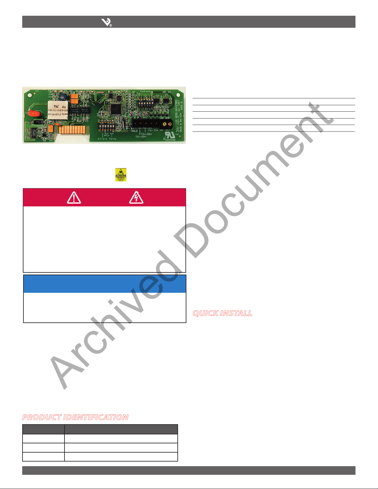
H8186-CB Energy Meter Communication Board is an optional field-installable board
for the H8163 Energy Meter that provides a simple, cost-effective way to network the
H8163 Energy Meter to an existing control/data acquisition systems via BACnet-
MS/TP communications capability. The H8186-CB is designed as a plug-and-play
accessory for the H8163 energy meter.
The H8186-CB features field selectable parity (odd/even/none). It works with 2-wire
and 4-wire systems, and it has a field selectable baud rate (9600, 19200, 38400).
oPeration configuration
Product diagram
ON
123456
ON
123456
1
2
TX
RX
3
RX
4
TX
5
6
7
8
9
ALIVE
LITHIUM BATTERY
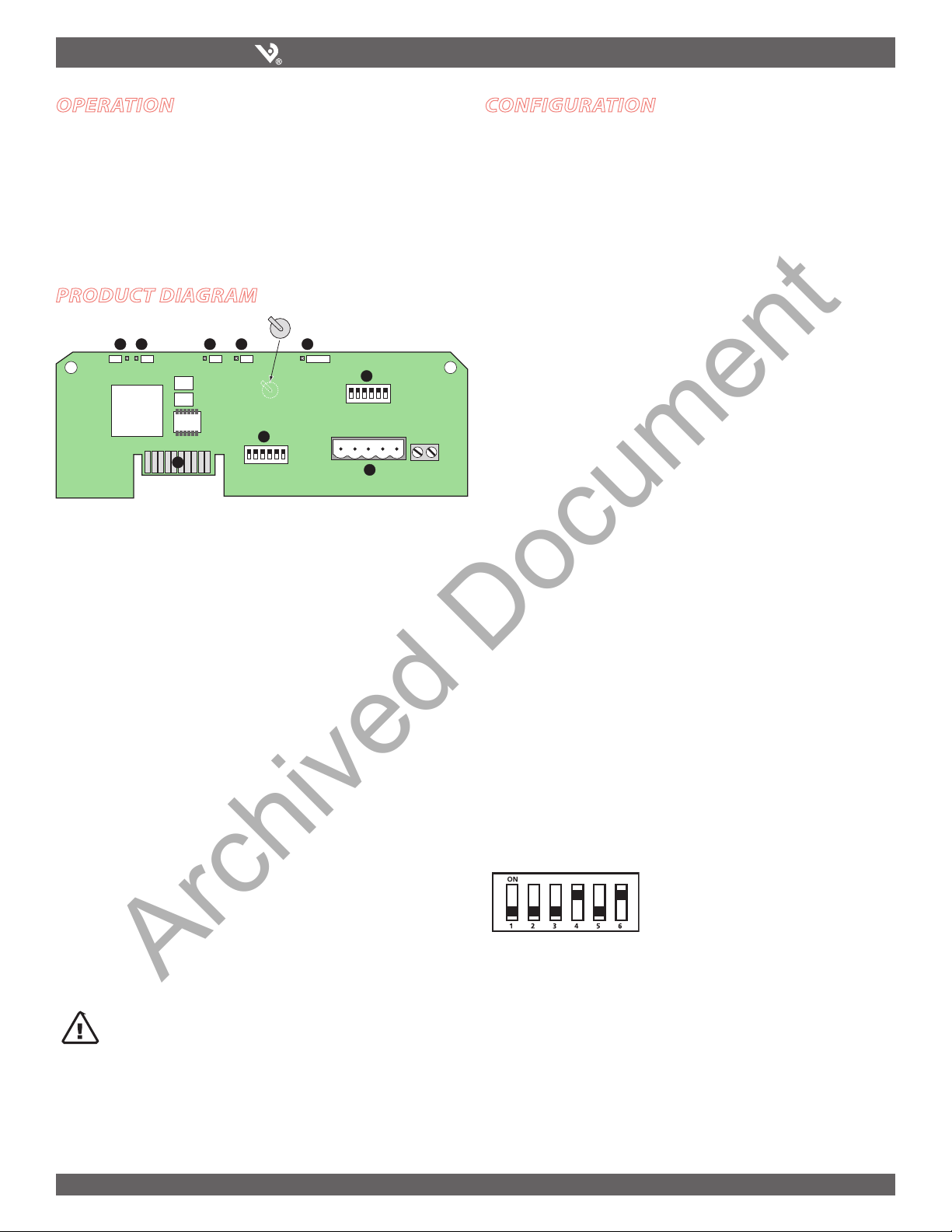
1. RS-485 LED (TX): Red LED; blinks to indicate that the H8186-CB is transmitting
data to the master.
2. RS-485 LED (RX): Red LED; blinks to indicate that the H8186-CB is receiving data
from the master.
3. LED from Main Board (RX): Green LED; blinks to indicate that the H8186-CB is
receiving data from the main board.
4. LED from Main Board (TX): Green LED; blinks to indicate that the H8186-CB is
transmitting data to the main board.
5. “ALIVE” LED: Green LED; should blink once per second to indicate normal
operation of the H8186-CB.
6. Network Address DIP Switches: Use these DIP switches to set the network
address for the H8186-CB.
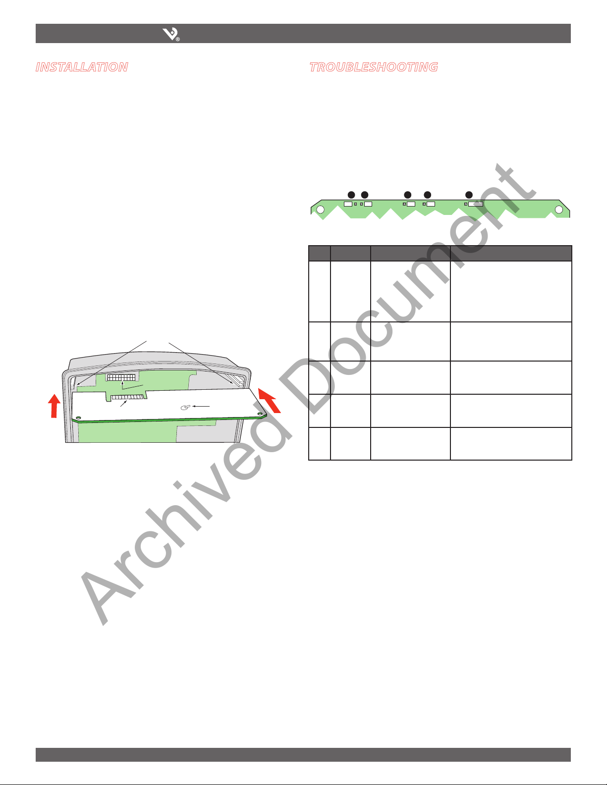
7. Connection to Energy Meter: Install the H8186-CB in the energy meter by
inserting this connector into the connection slot at the top of the energy meter.
8. Communication DIP Switches: Use these DIP switches to set the H8186-CB
wiring type, baud rate, and parity.
9. RS-485 Communication Terminals: Insert the RS-485 connector into these
terminals. See the Wiring Diagram section of this guide for instructions on wiring
the connector for 2-wire or 4-wire communications.
CAUTION! Danger of Explosion if battery is incorrectly
replaced. Replace only with the same or equivalent type
recommended by the manufacturer. Dispose of used
batteries according to the manufacturer’s instructions.
This section describes the communications settings you must make to the H8186-CB.
When daisy-chaining devices, follow these guidelines:
You can connect up to 63 H8186-CB devices on a single daisy chain.•
Each H8186-CB device on the daisy chain must have a unique address.•
Before connecting the H8186-CB to the RS-485 communication wires,
set the address according to directions in “Selecting the Network Address
DIP Switches” on this page. If you assign the same address to two devices,
neither device will communicate.
Set the wiring type, baud rate, and parity according to directions in•
“Selecting Wiring Type, Baud Rate, and Parity—Communication DIP
Switches” on this page. The settings for each H8186-CB must match the
other devices on its daisy chain.
For RS-485 cables, use shielded, twisted-pair wire (Belden Cable 1120A or•
equivalent).
Terminate the last device on the daisy chain. If the H8186-CB is the last•
device, per the RS-485 standard (120 ohm nominal impedence).
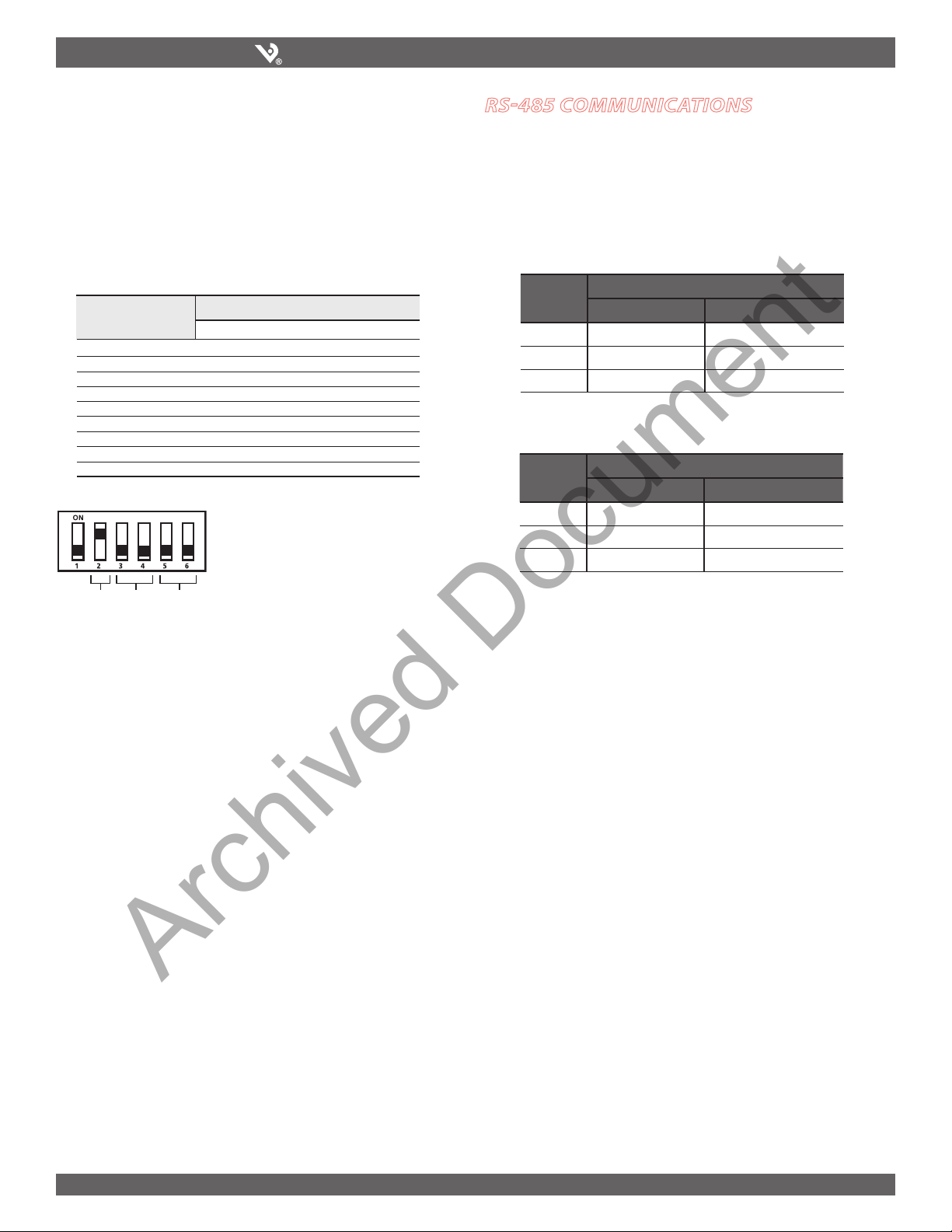
Selecting The Network Address – DIP Switches
Use the Network Address DIP switches to select the network address. Each H8186-CB
on a daisy chain must have a unique network address (from 0–63). Devices with the
same address will be unable to communicate.
Always set the address before you install the H8186-CB in the energy meter and
before you connect the energy meter to the daisy chain.
Each of the six DIP switches has a unique address value, page 8 lists DIP switch posi-
tions for specific addresses.
Network Address DIP Switch Values
Switch Value
1 1
2 2
3 4
4 8
5 16
6 32
8 + 32 = 40
In this example, the network address for the
device is 40. Switch 4 and 6 offer the only
combination of values that total 40.
This figure illustrates how to set the
switches. Up is ON; down is OFF.
Archived Document

6%2)3).$5342)%3
H8186-CB INSTALLATION GUIDE
Z204062-0E page 3 ©2008 Veris Industries USA 800.354.8556 or 503.598.4564 / suppor[email protected] 06081
Selecting Wiring Type, Baud Rate, and Parity– Communication DIP Switches
Use the communication DIP switches (pictured below) to set the H8186-CB wiring
type, baud rate, and parity.
The figures below list the baud rate and parity switch settings and the locations of
the switches that control wiring, baud rate, and parity.
Wiring, Baud Rate, and Parity Settings
Parameter
1
–
–
–
–
–
–
–
–
–
2
ON
OFF
3
OFF
ON
OFF
ON
4
OFF
OFF
ON
ON
5
OFF
ON
ON
6
OFF
OFF
ON
2-wire
4-wire
9600
19200
38400
38400
None
Even
Odd
Wire
Ty pe
Baud
Rate
Parity
Switch Number and Setting
Switch 1 is unused. Always leave it in the OFF
position.
This example illustrates the default switch settings
for a 2-wire device that uses 9600 baud rate no
parity.
Wiring
Baud
Parity
Daisy Chain Maximum Distances
The maximum number of devices capable of being supported on a single daisy chain
is determined based on the combination of baud rate, the length of the daisy chain,
and the types of RS-485 devices (2-wire/4-wire) on the daisy chain. The RS-485
interface will support daisy chains that fall within the specifications shown below.
Baud Rate Maximum Distances
1-16 Devices 17-32 Devices
9600 10000 ft. (3048 m) 4000 ft. (1219 m)
19200 5000 ft. (1,524 m) 2500 ft. (762 m)
38400 2500 ft. (762 m) 1200 ft. (380 m)
Baud Rate Maximum Distances
1-8 Devices 9-16 Devices
9600 10000 ft. (3048 m) 4000 ft. (1219 m)
19200 5000 ft. (1,524 m) 2500 ft. (762 m)
38400 2500 ft. (762 m) 1200 ft. (380 m)
2-Wire Daisy Chain Maximum Distances
Wiring the Connector
Remove the connector from the RS-485 communication terminals of the H8186-CB
(see Wiring Diagram section). To wire RS-485 communications, follow these steps:
1. Wire the communications connector for either 2-wire communication or 4-wire
communication (see Wiring Diagram section).
NOTE: The Wire Type setting in the communication DIP switch must match this
wiring type (see settings diagram, previous section, for communication DIP switch
settings).
2. Use a small, flat-blade screwdriver to tighten the connector screws.
3. Replace the connector on the RS-485 communication terminals of the H8186-CB.
4. If the H8186-CB is the last device on the daisy chain, terminate it, to ensure
reliable communication per the RS-485 standard (120 Ω nominal impedence).
rs-485 communications
4-Wire Daisy Chain Maximum Distances
Archived Document

6%2)3).$5342)%3
H8186-CB INSTALLATION GUIDE
Z204062-0E page 4 ©2008 Veris Industries USA 800.354.8556 or 503.598.4564 / suppor[email protected] 06081
wiring diagram
TX+
SHLD
TX+
RX+
TX–
RX–TX–
SHIELD
ON
123456
ON
123456
TX RX RX ALIVE
SHLD
TX-/RX-
TX+/RX+TX-TX+
TX+
SHLD
TX+
RX+
TX–
RX–TX–
MASTER SLAVE
ON
123456
ON
123456
TX RX RX ALIVE
SHLD
TX-/RX-
TX+/RX+
TX-TX+
TX+
SHLD
TX+
RX+
TX–
RX–TX–
TX+
SHLD RX+
RX–TX–TX+
SHLD
TX+
RX+
TX–
RX–TX–
SHIELD
RX-
RX+
TX-
TX+
MASTER SLAVESLAVE
2-wire Communications Wiring
4-wire Communications Wiring
Detail showing Communications connector
wired for 2-wire communication.
Detail showing Communications
connector wired for 4-wire
communication.
Figure 6
Figure 7
Archived Document

6%2)3).$5342)%3
H8186-CB INSTALLATION GUIDE
Z204062-0E page 5 ©2008 Veris Industries USA 800.354.8556 or 503.598.4564 / suppor[email protected] 06081
Before beginning this procedure, set the wiring, baud rate, and parity using the
Communication DIP switches, and set the network address using the Network
Address DIP switches (see the Configuration section on page 2 of this installation
guide).
1. Turn off all power to the energy meter and the equipment in which it is
installed:
a. Remove the voltage terminal from the energy meter
and all fuses.
b. Always use a properly rated voltage sensing device to
confirm that power is off.
2. To discharge static, follow the instructions that come with your
anti-static or grounding strap.
NOTE: Use an anti-static or grounding
strap at all times during installation.
3. Slide the H8186-CB into the slot in the energy meter. The sides of the H8186-CB
slide down into the channels on either side of the energy meter. When the male
connection to the energy meter (see below) clicks into place, the H8186-CB is
properly installed.
troubleshooting
CAUTION: ESD-SENSITIVE COMPONENTS
Use an anti-static or grounding strap (customer-supplied) to ground yourself and
discharge any static charge before installing the H8163-CB. Static can damage
electrostatic discharge-sensitive components in the circuit monitor and its
accessories. Failure to follow this instruction can result in equipment damage.
SLOTS
TOP
COMMS BOARD
BATTERY
CONNECTORS
CONNECTION
SLOTS
4. Insert the communication terminal onto the RS-485 communication
terminals.
5. If the demand subinterval feature is used, wire into the end of the demand
subinterval terminal.
6. Replace the voltage terminal into the energy meter.
There are five LEDs that indicate various types of communication. The figure below
indicates the locations of these LEDs. All LEDs will blink when operating normally.
If there is a problem communicating, first be sure that the board is properly seated
in its slot on the energy meter. Verify that the sides of the H8186-CB are in the slots
on the sides of the energy meter and that the connector has clicked into place in the
connection slot of the energy meter. If all these factors are normal, see the table
below to interpret the LED blink codes.
ON
123456
ON
123456
1
2
TX
RX
3
RX
4
TX
5
6
7
8
9
10
ALIVE
D5 D6 D13 D14 D1
LED Abnormal Operation Solution
1 RS-485 LED
(TX)
Not Blinking There is no communication from the
H8163 to the master. Check the wiring;
TX+/TX- and RX+/RX- may be reversed.
Correct the wiring. If RX is blinking,
verify the DIP switch address, parity,
baud rate, and wire type.
2 RS-485
(RX)
Not Blinking There is no communication from the
master. The RX+ and RX- wires are
reversed. Correct the wiring.
3 From main
board
(RX)
Not blinking The main board is not responding.
Contact the factory for support.
4 From main
board
(TX)
Not blinking but“Alive”
LED is blinking
There is an internal communications
board error. Contact the factory.
5 “Alive”
status
Steadily lit There is an internal communications
board error. Contact the factory for
support.
LED positions on the EMCB
installation
Archived Document

6%2)3).$5342)%3
H8186-CB INSTALLATION GUIDE
Z204062-0E page 6 ©2008 Veris Industries USA 800.354.8556 or 503.598.4564 / suppor[email protected] 06081
The figure below illustrates the switch settings, using the Network Address DIP switches, for each Network address. See "Selecting the network Address -
NETWORK ADDRESS DIP SWITCHES" on pages 2-3 for instruction on setting the switches.
32
33 34 35 36 37 38 39 40 41 42 43
44 45 46 47 48 49 50 51 52 53 54
55 56 57 58 59 60 61 62 63
012345678910
11 12 13 14 15 16 17 18 19 20 21
22 23 24 25 26 27 28 29 30 31
network address settings
Archived Document

6%2)3).$5342)%3
H8186-CB INSTALLATION GUIDE
Z204062-0E page 7 ©2008 Veris Industries USA 800.354.8556 or 503.598.4564 / suppor[email protected] 06081
BACnet Object Description Description Field Units
Device Object: This device Veris H81xx Energy N/A
Meter with H8186-CB
BACnet Communications Board
Analog Value Object 1: Accumulated Energy kWh_Total kWh
Analog Value Object 2: Device Instance Device_Instance N/A
Analog Input Object 1: Total Real Power kW_Total kW
Analog Input Object 2: Total Reactive Power kVAR_Total kW
Analog Input Object 3: Total Apparent Power kVA_Total kW
Analog Input Object 4: Total Power Factor PF_Total Unitless
Analog Input Object 5: Average Line-Line Voltage Volts_LL_Avg VOLTS
Analog Input Object 6: Average Line-Nuetral Voltage Volts_LN_Avg VOLTS
Analog Input Object 7: Average Current Current_Avg AMPS
Analog Input Object 8: Real Power: Phase A kW_A kW
Analog Input Object 9: Real Power: Phase B kW_B kW
Analog Input Object 10: Real Power: Phase C kW_C kW
Analog Input Object 11: Power Factor: Phase A PF_A Unitless
Analog Input Object 12: Power Factor: Phase B PF_B Unitless
Analog Input Object 13: Power Factor: Phase C PF_C Unitless
Analog Input Object 14: Voltage: Phase A-Phase B Volts_AB VOLTS
Analog Input Object 15: Voltage: Phase B-Phase C Volts_BC VOLTS
Analog Input Object 16: Voltage: Phase A-Phase C Volts_AC VOLTS
Analog Input Object 17: Voltage: Phase A-Neutral Volts_AN VOLTS
Analog Input Object 18: Voltage: Phase B-Neutral Volts_BN VOLTS
Analog Input Object 19: Voltage: Phase C-Neutral Volts_CN VOLTS
Analog Input Object 20: Current: Phase A Current_A AMPS
Analog Input Object 21: Current: Phase B Current_A AMPS
Analog Input Object 22: Current: Phase C Current_A AMPS
Clearing the kWhAccumulator: Clear the kWh accumulator to zero by writing 0.0 to the PRESENT_VALUE property Analog Value Object 1.
Changing the Device_Instance:
• Units are shipped with a default Device Instance of 123.
There are 2 methods of changing the Device_Instance:•
1. Write the Object_Identifier directly. The Device’s Object_Identifier contains both the Object_Type (Device = 8) and the Object_Instance (0-4194302). Write the
Device’s Object_Identifier with (8,Instance) to change the Device_Instance.
2. Use Analog Value Object 2. Although a REAL (i.e. floating point) value, writing the Present_Value of AV2 is an alternative method of changing the Device_In
stance. This value may be written in the range 0-4194302. Any fractional value will be truncated (eg. 57.234 will be written as 57).
bacnet descriPtions
Archived Document

6%2)3).$5342)%3
H8186-CB INSTALLATION GUIDE
Z204062-0E page 8 ©2008 Veris Industries USA 800.354.8556 or 503.598.4564 / suppor[email protected] 06081
BACnet Protocol Implementation Conformance Statement
Date: August 2, 2007
Vendor Name: Veris Industries
Product Name: BACnet Communications Board for
H81xx Energy Meter
Product Model Number: H8186-CB
Applications Software Version: 1
Firmware Revision: 1.09
BACnet Protocol Revision: 2
Product Description: Provides BACnet MS/TP connectivity to
the Veris H81xx Energy Meter
BACnet Standardized Device Profile (Annex L):
BACnet Application Specific Controller (B-ASC)
List all BACnet Interoperability Building Blocks Supported (Annex K):
DS-RP-B, DS-RPM-B, DS-WP-B, DM-DDB-B, DM-DOB-B, DM-DCC-B
Segmentation Capability:
Segmentation not supported
Standard Object Types Supported:
No dynamic Creation or Deletion supported
No proprietary properties or object types
Device Object:
Optional Properties Supported:
Max_Master, Max_Info_Frames, Description, Location
Writable Properties:
Object_Identifier, Max_Master, Location
Property Range Restrictions:
Location (limited to 64 characters)
Analog Input Object:
Optional Properties Supported:
Description
No Writable Properties.
Analog Value Object:
Optional Properties Supported:
Description
Writable Properties:
Only the Present_Value is writable.
Property Range Restrictions:
1) Only the value 0.0 may be written to the Present_Value
of AV1. This action will clear the kWh-Accumulator in the
H81xx Energy Meter.
2) Although a REAL (i.e. floating point) value, writing the
Present_Value of AV2 is an alternative method of changing
the Device_Instance. This value may be written in the range
0-4194302. Any fractional value will be truncated (eg. 57.234
will be written as 57).
Data Link Layer Options:
MS/TP master (Clause 9), baud rate(s): 9600, 19200, 38400
Device Address Binding:
Static device binding is not supported. (No client functionality is included).
Networking Options:
None
Character Sets Supported:
ANSI X3.4
bacnet Protocol
Archived Document
Other manuals for H8163-CB
1
This manual suits for next models
2
Table of contents
Other Veris Industries Conference System manuals