Visonic Ltd DL-125B User manual
DE5802 1
'/%
Automatic Telephone Dialer Installation Instructions
,1752'8&7,21
The Visonic Ltd. DL-125B Automatic Telephone Dialer initiates
telephone communications upon receipt of a trigger pulse, and is
intended for unattended operation at a remote location. It dials
preprogrammed numbers and then transmits either an identifying
alarm code or an optional voice message from an external
source. A non-volatile memory includes 9 memory cells for
retaining 9 telephone numbers (Cells 1 to 9) and a single memory
cell (Cell 0) for storing one of 10 possible identification codes. An
identification code contains a sequence of swept-tone bursts –
from 1 to 10 bursts – as programmed by the installer. This
sequence is repeated at 3-second intervals within a 60-second
time frame. The Dialer's operation routine is as follows:
1. When The DL-125B receives an input trigger pulse, it
disconnects any telephones that are connected to the
telephone line via its SET terminals, and dials the
programmed number in Memory Cell No 1.
2a. If no external audio device is connected, the dialer repeatedly
transmits its identification code for approximately one minute.
If that code consists, for example, of three rising tone bursts
(Code 3), three 1/2 sec bursts are transmitted, separated by
intervals of 1/2 sec (1 Hz). The three bursts are repeated at
3-second intervals for one minute.
2b. If a source of external audio, such as a cassette player or an
electronic speech processor is connected, it is switched on
and the recorded message is transmitted.
3. The dialer then hangs up and switches off the audio source, if
used, and immediately dials the telephone number in Memory
Cell No. 2. It transmits its identification code or audio
message for approximately one minute, as in Step 2. A
closed-loop cassette should be used in the tape recorder.
4. The dialer repeats Step 3 for the third telephone number and
so on until it completes the process with the last programmed
telephone number.
5. The entire cycle is repeated once more for all of the
programmed telephone numbers, and then the dialer
disconnects itself and reconnects the telephones sharing the
line with it.
Note: The shortest complete cycle occurs if a single telephone
number is programmed: that number is dialed twice. The longest
cycle consists of nine telephone numbers: 18 numbers are
dialed. If the same number is programmed into all 9 available
memory cells, that number is dialed 18 times.
63(&,),&$7,216
GENERAL
Input voltage: 10.5 to 16 VDC
Standby input current: none.
Operating input current: 120 mA at 12 VDC
Dimensions: 7 x 10 cm
TELEPHONE LINE
Dialing method: Pulse, 10 pps
Telephone numbers: 1 to 9, with programmable priorities
Digits per telephone number: 1 to 16, programmable
EXTERNAL AUDIO
External audio input impedance: Approximately 500 ohms,
capacitor coupled
External audio input level: 0 dBm nominal
Duration of audio input signal: 45 seconds maximum
External audio switching contacts: 24 VDC, 2 A maximum
,167$//$7,21
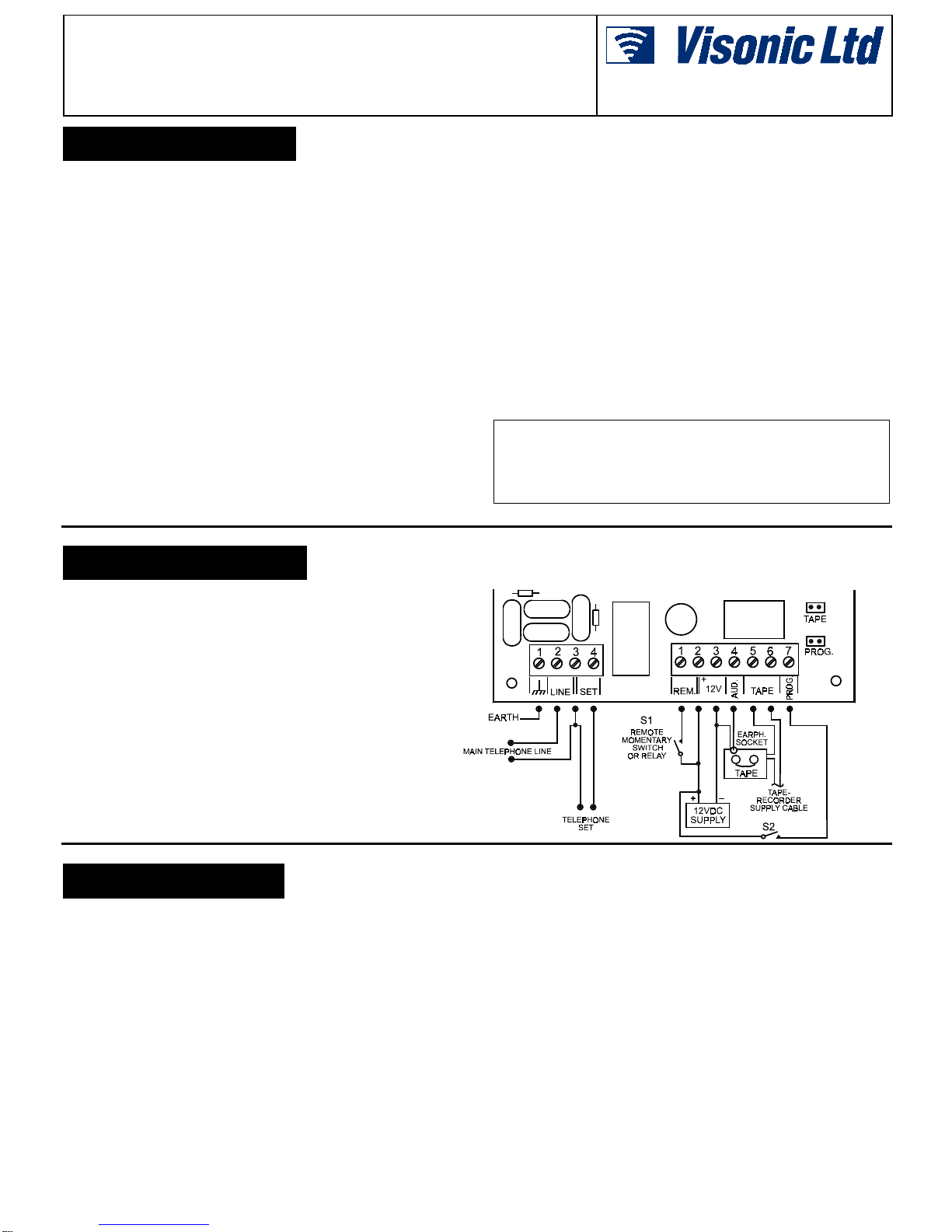
(/(&75,&$/&211(&7,216
Ground An external ground terminal, to establish a protective
ground for the telephone lines. This terminal is
electrically isolated from the circuit ground of the
Automatic Dialer.
LINE Terminal pair for connecting any standard telephone line
utilizing pulse dialing. The four SET, LINE and ground
terminals are isolated from the other terminals of the
Automatic Dialer.
SET Terminal pair for connecting rotary or pushbutton
telephone sets, using the line to which the Automatic
Dialer is connected. Ensure that all telephone sets are
connected to the line only via the SET terminals! One
terminal is common to both SET and LINE.
REM Connect a normally open switch between this terminal
and the 12V (+) terminal. Closing the switch for at least
100 ms (0.1 sec) actuates the Automatic Dialer; to
reduce false triggering, shorter closures are ignored.
12 V Terminal pair for connecting a source of 12 VDC.
AUD Connect this terminal to an optional source of external
audio, usually the center conductor of the earphone jack
of a cassette player. Bring the outer conductor to the
12V (–) negative supply terminal.
TAPE These are floating, normally open contacts, to switch on
an external audio source (a cassette player or an
electronic speech processor). If such a device is used,
install a jumper across the two TAPE pins on the printed
circuit board. If a source of external audio is not used,
place the TAPE jumper on a single pin to prevent losing
it.
PROG Connect this terminal to the 12V (+) to switch the dialer
to the programming mode. The same result is obtained
by placing a jumper across the two PROG pins on the
printed circuit board.
2DE5802
352*5$00,1*
The Automatic Dialer is shipped already programmed for sending
a sequence of 10 tone bursts over the line (code 10) but has no
telephone number programmed; it will not function until at least
one number is programmed. Each telephone number is entered
into a memory cell, numbered from 1 to 9. No. 1 has highest
priority and is dialed first, whereas No. 9 is dialed last. To dial the
same number more than twice, enter it into two or more memory
cells.
1. Connect a pulse dialing telephone to the dialer's SET
terminals (most probably such a telephone set is already
connected to the SET terminals).
2. Apply power to the Automatic Dialer, and either install the
PROG jumper across its two pins or supply +12V to the
PROG terminal. After approximately two seconds, the red
light-emitting diode (LED) lights. Wait at least three seconds
before proceeding to step 3.
3. After the red LED has been lit for at least three seconds, lift
the telephone handset from its cradle.
4. To program a telephone number, simply dial the desired
number, followed by another, single digit from 1 to 9 to define
the memory cell which will retain that telephone number.
Thus, to program the number 936 2611 and to save it in
memory cell No. 9, dial 936 2611 9. Put the handset back in
its cradle and wait 2 seconds before proceeding. If you use a
pushbutton telephone, listen to ensure that dialing is
completed before hanging up.
5. To program other telephone numbers, repeat the procedure
outlined in step 4 above.
6. To program a new identification code instead of the factory
programmed 10 swept-tone bursts, lift the telephone handset
once more and dial a single digit defining the number of
desired tone bursts, followed by the digit 0 , so that the
number of bursts would be saved in the correct memory cell –
Cell 0. For example, dial 30 to specify 3 tone bursts, or 70 to
specify 7 tone bursts. To save the new code in memory, put
the handset back in its cradle and wait 2 seconds
8. To delete a telephone number, lift the telephone handset and
dial the single digit from 1to 9, denoting the number of the
memory cell in which the undesired number is retained. Hang
up the telephone handset for at least two seconds, as in the
previous steps.
9. When programming is completed, remove the jumper from the
PROG pins (or remove +12V from the PROG terminal).
CLEARING PROGRAMMING ERRORS: If an error occurs
during programming, the red LED blinks and further
programming is not possible. To clear the error and resume
programming: hang up the telephone handset, wait
approximately three seconds after the LED stops blinking, lift
the handset, and resume programming.
7(67,1*
The DL-125B Automatic Dialer should be tested after it has been
installed, connected and programmed. To test it:
1. Apply power to the dialer and momentarily connect the two
REM terminals together. The dialer will perform its routine.
2. When the entire operating cycle is finished, call all numbers
programmed in the dialer's memory and verify with all call
recipients that the dialer's calls were received and that the
identification code or voice message was fully and clearly
received. If a programming error is discovered, reprogram the
dialer, carefully following the written programming instructions.
:$55$17<
:$55$17<
Visonic Ltd. and/or its subsidiaries and its affiliates ("the Manufacturer") warrants its
products hereinafter referred to as "the Product" or "Products" to be in conformance with
its own plans and specifications and to be free of defects in materials and workmanship
under normal use and service for a period of twelve months from the date of shipment by
the Manufacturer. The Manufacturer's obligations shall be limited within the warranty
period, at its option, to repair or replace the product or any part thereof. The Manufacturer
shall not be responsible for dismantling and/or reinstallation charges. To exercise the
warranty the product must be returned to the Manufacturer freight prepaid and insured.
This warranty does not apply in the following cases: improper installation, misuse,
failure to follow installation and operating instructions, alteration, abuse, accident or
tampering, and repair by anyone other than the Manufacturer.
This warranty is exclusive and expressly in lieu of all other warranties, obligations or
liabilities, whether written, oral, express or implied, including any warranty of
merchantability or fitness for a particular purpose, or otherwise. In no case shall the
Manufacturer be liable to anyone for any consequential or incidental damages for breach
of this warranty or any other warranties whatsoever, as aforesaid.
This warranty shall not be modified, varied or extended, and the Manufacturer does not
authorize any person to act on its behalf in the modification, variation or extension of this
warranty. This warranty shall apply to the Product only. All products, accessories or
attachments of others used in conjunction with the Product, including batteries, shall be
covered solely by their own warranty, if any. The Manufacturer shall not be liable for any
damage or loss whatsoever, whether directly, indirectly, incidentally, consequentially or
otherwise, caused by the malfunction of the Product due to products, accessories, or
attachments of others, including batteries, used in conjunction with the Products.
The Manufacturer does not represent that its Product may not be compromised and/or
circumvented, or that the Product will prevent any death, personal and/or bodily injury
and/or damage to property resulting from burglary, robbery, fire or otherwise, or that the
Product will in all cases provide adequate warning or protection. User understands that a
properly installed and maintained alarm may only reduce the risk of events such as
burglary, robbery, and fire without warning, but it is not insurance or a guarantee that such
will not occur or that there will be no death, personal damage and/or damage to property
as a result.
The Manufacturer shall have no liability for any death, personal and/or bodily injury
and/or damage to property or other loss whether direct, indirect, incidental,
consequential or otherwise, based on a claim that the Product failed to function.
However, if the Manufacturer is held liable, whether directly or indirectly, for any loss or
damage arising under this limited warranty or otherwise, regardless of cause or origin, the
Manufacturer's maximum liability shall not in any case exceed the purchase price of the
Product, which shall be fixed as liquidated damages and not as a penalty, and shall be the
complete and exclusive remedy against the Manufacturer.
Warning: The user should follow the installation and operation instructions and among
other things test the Product and the whole system at least once a week. For various
reasons, including, but not limited to, changes in environmental conditions, electric or
electronic disruptions and tampering, the Product may not perform as expected. The user
is advised to take all necessary precautions for his /her safety and the protection of
his/her property. 6/91
VISONIC LTD. (ISRAEL): P.O.B 22020 TEL-AVIV 61220 ISRAEL. PHONE: (972-3) 645-6789, FAX: (972-3) 645-6788
VISONIC INC. (U.S.A.): 10 NORTHWOOD DRIVE, BLOOMFIELD CT. 06002-1911. PHONE: (860) 243-0833, (800) 223-0020 FAX: (860) 242-8094
VISONIC LTD. (UK): UNIT 1, STRATTON PARK, DUNTON LANE, BIGGLESWADE, BEDS. SG18 8QS. PHONE: (01767) 600857 FAX: (01767) 601098
VISONIC LTD. 1998 DL-125B D-5802-0 NEW : DE5802- (REV. 2, 4/98)
Table of contents


