Z
20
7932-
0
C
Page 2 of 12 ©2020 Veris Industries USA 800.354.8556 or +1.503.598.4564 / supp[email protected] 0920 Alta Labs, Enercept, Enspector, Hawkeye, Trustat, Aerospond, Veris, and the Veris ‘V’ logo are trademarks or registered trademarks of Veris Industries, L.L.C. in the USA and/or other countries.
Other companies’ trademarks are hereby acknowledged to belong to their respective owners.
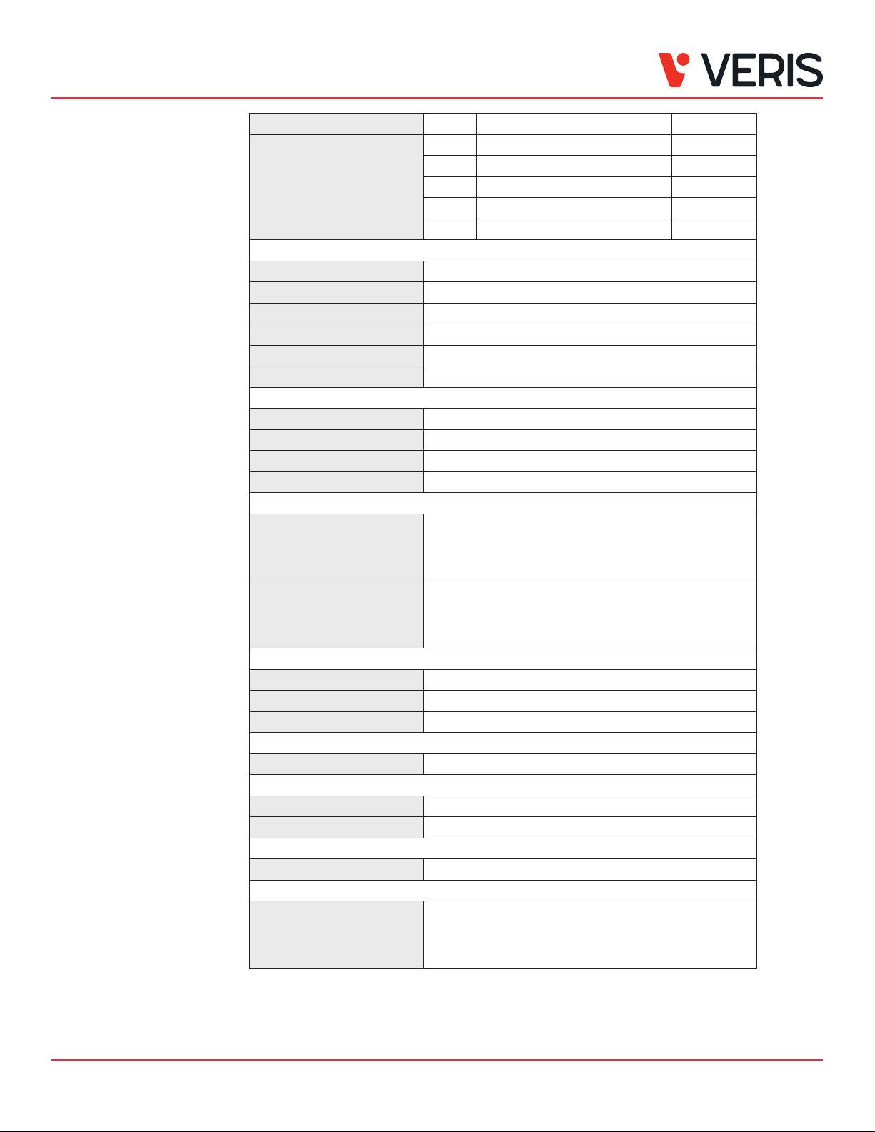
CW2 Protocol Series Installation Guide
Specications (cont.) Level Ventilation Recommendation TVOC (ppb)
AQI Table* >61% Greatly increased >610
20 to 61% Signicantly increased 200 to 610
10 to 20% Slightly increased 100 to 200
5 to 10% Average 50 to 100
0 to 5% Target value 0 to 50
RH TRANSMITTER OPTION
HS Sensor Thin-lm capacitive, replaceable
Accuracy ±2% from 10 to 80% RH @ 25°C (77 °F)
Hysteresis 1.5% typical
Stability ±1% @ 20°C (68 °F) annually for 2 years
Output Range 0 to 100% RH
Temperature Coecient ±0.1% RH/°C above or below 25 °C (77 °F) typical
TEMPERATURE TRANSMITTER
Sensor Type Solid state, integrated circuit
Accuracy ±0.2 °C (±0.4 °F) typical
Resolution 0.1 °C (0.1 °F)
Range 0 to 50 °C (32 to 122 °F)
DISPLAY MODELS
Touchscreen 61 mm (2.4 in), color, backlit, capacitive, 240x300 px
Setpoint: Temperature, humidity or fan speed selectable
Timeout override: Display timeout
Lockout override: Touchscreen/button lockout
LCD 52mm (2.05 in), segmented with 3 buttons
Setpoint: Temperature, humidity or fan speed selectable
Timeout override: Display timeout
Lockout override: Touchscreen/button lockout
SETPOINTS
Temperature Setpoint Scale: 0 to 50 °C (32 to 122 °F) or 10 to 35 °C (50 to 95 °F) max., adjustable span
Humidity Setpoint Scale: 0 to 100% RH
Fan Speed Setpoint O, Low, Medium, High
OVERRIDE
Override Button Display models feature a momentary override button
WIRING TERMINALS
Terminal Blocks Screw terminals, 18-24 AWG
Screw Terminal Torque 0.2 N-m (2.0 in-lbF) max.
WARRANTY
Limited Warranty 5 years
COMPLIANCE INFORMATION
Agency Approvals UL 916, European conformance CE: EN61000-6-2,
EN61000-6-3, EN61000 Series - industrial immunity,
EN 61326-1
FCC Part 15 Class B, REACH, RoHS, RCM (Australia), ICES-003 (Canada)
* Air Quality Index for VOC aligns with TVOC levels for IAQ as specied by the WHO (World Health Organization).


