Veris MSCD2000D User manual

ZL0030-0C PAGE 1 ©2012 Veris Industries USA 800.354.8556 or +1.503.598.4564 / suppor[email protected] 02121
Alta Labs, Enercept, Enspector, Hawkeye, Trustat, Veris, and the Veris ‘V’ logo are trademarks or registered trademarks of Veris Industries, L.L.C. in the USA and/or other countries.
TM
OCCUPANCY SENSORS INSTALLATION GUIDE
Ceiling Mounted Occupancy Sensors
Installer’s Specifications
Input Voltage 24 VDC
Current Consumption @ 24 VDC:
PIR 21 mA nominal
Ultrasonic 34 mA nominal
Dual 37 mA nominal
Isolated Relay Contact rating: 1A @ 24 VDC resistive
Operating Temperature Range 0° to 50°C (32°to 122°F)
Operating Humidity Range Max. 90% RH non-condensing
Agency Approvals UL and cUL listed; FCC part 15 for home and oce use (Class B)
MSC SerieS MSC SerieS
NOTICE
• This product is not intended for life or safety applications.
• Do not install this product in hazardous or classified locations.
• Read and understand the instructions before installing
this product.
• Turn off all power supplying equipment before working on it.
• The installer is responsible for conformance to all applicable codes.
PRODUCT IDENTIFICATION
MSCD2000D MSCP1000
MSCU2000
Sensing Technology
U = Ultrasonic
D = Dual (PIR + Ultrasonic)
P= Passive Infrared (PIR)
MSC
Coverage
1000 = 1000 Sq. Ft. (Passive Infared only)
2000 = 2000 Sq. Ft. (Ultrasonic or Dual technology only)
COVERAGE PATTERNS
For a 9 ft. ceiling
Minor Motion
Major Motion
25 ft
(7.7m)
32 ft
(9.8m)
48 ft
(14.7m)
30 ft
(9.2m)
24 ft
(7.4m)
42 ft
(12.8m)
Minor Motion
Major Motion
Ultrasonic Major Motion
Ultrasonic Minor Motion
PIR Major Motion
PIR Minor Motion
PIR Ultrasonic
Dual Technology
OPERATION
MSC ceiling-mounted occupancy sensors are ideal for use in business and oce
environments to accurately detect occupancy and automatically control lighting. The
ceiling-mount design allows the greatest possible motion sensitivity. An adjustment
panel is on the front of the sensor provides easy access to controls after the sensor is
installed.
COVERAGE FEATURES
Model MSCP1000 MSCU2000 MSCD2000
Technology PIR Ultrasonic Dual
Coverage area 1000 sq. ft. 2000 sq. ft. 2000 sq. ft.
Field of view 360°
Ambient light level sensing 0.5 to 250 foot candles
Adjustable time delay 15 sec. to 30 min.
Adjustable sensitivity 600 to 1000 sq. ft.
(60% to 100% of
max. coverage
200 to 2000 sq. ft.
(10% to 100% of
max. coverage)
200 to 2000 sq. ft.
(10% to 100% of
max. coverage)
Isolated relay Form C contacts for Class 2 signaling
LED motion indicators 1 (red) 1 (red) 2 (red/green)

ZL0030-0C PAGE 2 ©2012 Veris Industries USA 800.354.8556 or +1.503.598.4564 / suppor[email protected] 02121
Alta Labs, Enercept, Enspector, Hawkeye, Trustat, Veris, and the Veris ‘V’ logo are trademarks or registered trademarks of Veris Industries, L.L.C. in the USA and/or other countries.
TM
MSC SERIES INSTALLATION GUIDE
INSTALLATION
Choose a location at least ve feet from air ow sources (HVAC vents, fans, etc.). Three
mounting options are available.
Mounting with Supplied Mounting Post
Washer
Ceiling tile
Lock Nut
Mounting post
1. Turn o the circuit breaker supplying power to the sensor’s power pack.
2. Drill a 7/8” diameter hole at the mounting location. Note: For acoustical tile, use
the threaded mounting post to drill the mounting hole. Press the cutter end of the
post rmly against the tile and twist the post into the tile.
3. Feed sensor wire through the mounting post, then twist and lock the mounting
post to the back of the sensor.
4. Insert the mounting post into the hole drilled in step 2. Secure the sensor
assembly away from the top of the ceiling tile using the supplied washer and lock
nut.
5. Wire the sensor (see Wiring section). Follow applicable national and local electrical
codes.
Mounting to a Junction Box
Junction Box
Mounting Adapter Plate
Rotate Clockwise
Keyhole Pin
#8 x 32 screw
1. Turn o the circuit breaker supplying power to the sensor’s power pack.
2. Attach the adapter plate to a standard 4-in. ceiling junction box using the two #8 x
32 screws supplied.
3. Wire the sensor (see Wiring section). Follow applicable national and local electrical
codes.
4. Attach the sensor to the adapter plate by inserting the pins on the adapter plate
into the keyholes on the back of the sensor. Rotate the sensor clockwise until it
locks in place.
Flush Mounting
Mounting Adapter Plate
Rotate Clockwise
Ceiling
Mounting Screw
Keyhole Pin
1. Turn o the circuit breaker supplying power to the sensor’s power pack.
2. Drill a hole large enough to accomodate wiring at the mounting location.
3. Attach the adapter plate to the ceiling using a secure method, such as with screws
and wall anchors (not provided).
4. Wire the sensor (see Wiring section). Follow applicable national and local electrical
codes.
5. Attach the sensor to the adapter plate by inserting the pins on the adapter plate
into the keyholes on the back of the sensor. Rotate the sensor until it locks in
place.
WIRING
Contact rating:
1A @ 24Vdc Resistive
Hot
Neutral
Black
White
Red
Black
Blue
Red
Black
Blue
Red
Black
Blue
Red
Orange (N.O.)
Yellow(Common)
Green (N.C.)
Power Pack
AA47
Load
Class 1
Class 2
Additional
Sensor(s)
(optional)
DIMENSIONS
4.6”
(117mm)
MSCU: 1.4”(36mm)
MSCD/MSCP: 1.8”(46mm)

ZL0030-0C PAGE 3 ©2012 Veris Industries USA 800.354.8556 or +1.503.598.4564 / suppor[email protected] 02121
Alta Labs, Enercept, Enspector, Hawkeye, Trustat, Veris, and the Veris ‘V’ logo are trademarks or registered trademarks of Veris Industries, L.L.C. in the USA and/or other countries.
TM
MSC SERIES INSTALLATION GUIDE
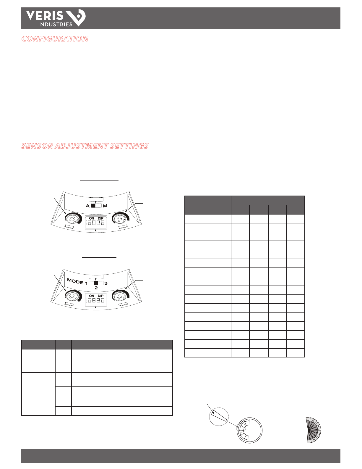
SENSOR ADJUSTMENT SETTINGS
The adjustment panel is located on the front of the sensor housing. Gently pry o the
cover with a small athead screwdriver.
PIR and Ultrasonic
1 432
Photocell Dial
Mode Switch
DIP Switches
SensitivityDial
Dual Technology
1 432
Photocell Dial
Mode Switch
DIP Switches
Sensitivity Dial
Mode Switch: Determines when lights are turned on or remain on.
Sensor Mode Description
PIR and
Ultrasonic
A Automatic mode. Normal, default setting. Lights turn on or
remain on only when the sensor detects motion.
M Manual override ON mode. Lights are always on.
Dual Technology
1 Instant ON setting. Either PIR or ultrasonic detection turns
the lights on or causes the lights to remain on.
2 Normal, default setting. Only PIR detection turns the lights
on. Either PIR or ultrasonic detection causes the lights to
remain on.
3 Override ON setting. Lights are always on.
Sensitivity Dial: Determines the amount of movement required to trigger the
sensor and the distance from which movement is detected. Turn the dial to the
desired setting (MSCP1000: 60% to 100% of max.; MSCU2000, MSCD2000: 10% to
100% of max.). The default sensitivity setting is 100%.
Note: Consider the characteristics of the room when adjusting the sensitivity of
the Ultrasonic and Dual Technology sensors. Hard surfaces (concrete, tile, glass)
are reective and create a higher sensitivity for ultrasonic detection. Soft surfaces
(carpet, drapes, acoustical tile) absorb some of the ultrasonic energy and reduce the
unit’s sensitivity. Building additions, such as cubicles and walls, may also require a
higher sensitivity setting.
Photocell Dial: Sets the level above which ambient light will not trigger the sensor.
Set the ambient light level from 0.5 to 250 foot-candles. Turn the dial to the desired
setting (minimum setting is fully countercockwise; maximum is fully clockwise). The
default photocell setting is 250 foot-candles. This setting also disables the photocell
(i.e., ambient light will not inhibit sensor operation).
Time Delay Switches: A set of four DIP switches determines how long lights will
stay on after motion is no longer detected. Settings range from 15 seconds to 30
minutes. The default time delay setting is 18 minutes. Possible DIP switch settings
are shown in the table below.
DIP Switch Number
Time Delay 1 2 3 4
15 sec. (test setting) • • • •
2 min. • • • —
4 min. • • —•
6 min. • • — —
8 min. •—• •
10 min. •—•—
12 min. •— — •
14 min. •— — —
16 min. — • • •
18 min. (default setting) — • • —
20 min. — •—•
22 min. — •— —
24 min. — — • •
26 min. — — •—
28 min. — — — •
30 min. — — — —
— = Off
•= On
To reduce unwanted detection, such as people moving in adjacent areas, partially
mask the lens of the PIR or Dual sensor with the supplied white masking strips.
Masking Strip
Sensor with Masking Field of View from the Top
CONFIGURATION
1. Turn on the circuit breaker and any wall switches that supply power to the sensor.
2. When rst installed, allow the sensor to warm up for a few minutes before it is
fully operational. When the sensor detects motion, the LED on the housing ashes
for approximately 0.5 seconds, and the lights turn on or remain on.
3. Set the Time Delay to the test setting of 15 seconds.
4. Vacate the room until the lights turn o.
5. Re-enter the room. Lights should turn on immediately. If not, verify correct sensor
wiring.
6. Adjust settings as desired.
This manual suits for next models
2
Other Veris Accessories manuals

Veris
Veris HWL Series Operating and maintenance instructions

Veris
Veris TW Series User manual

Veris
Veris CWE2 Series User manual

Veris
Veris CWV2 User manual

Veris
Veris CW2 Series User manual

Veris
Veris HW2T Series User manual

Veris
Veris HD series User manual

Veris
Veris HW2 Series User manual

Veris
Veris HAWKEYE 708 User manual

Veris
Veris CW2LA2A User manual