VERITAS Access 3340 Manual

Replacing the Storage Shelf rail kit
Document number: 325
Version: 1.1 (05/02/2022)
Purpose
This document describes the process for replacing the 5U84 Storage Shelf rails.
Affected appliance models
• 3340 Appliance
• 3350 Appliance
• 5340/5340 HA Appliance
• 5350/5350 HA Appliance
Electrical Safety
The static discharged by human bodies can damage static-sensitive components on the boards.
When installing and maintaining the equipment, observe appropriate electrostatic safety precautions
to prevent personnel injuries or device damage.
When operating a device in an electrostatic sensitive area, you must take electrostatic-discharge
(ESD)-preventive measures. These include wearing ESD-preventive gloves, an ESD-preventive wrist
strap, and ESD-preventive clothes to avoid personnel injury or device damage.
To prevent damage to the device, pay attention to the following during operations:
• Do not touch devices with bare hands because ESD from the human body may damage the
electrostatically sensitive elements on a board.
• When dealing with the server or any of the internal components, wear an ESD-preventive wrist
strap, ESD-preventive gloves, and ESD-preventive suit.
1
Veritas Appliance
Hardware Service Procedure

High availability (HA) appliance compute node and storage shelf
service considerations
Attention: When you service an HA or a multi-node appliance that requires the attached storage
shelves to be turned off, you must turn off the secondary compute node first before you turn off the
primary compute node.
When you turn on the storage shelves and compute nodes after completing the service, turn on the
primary compute node first before you turn on the secondary compute node.
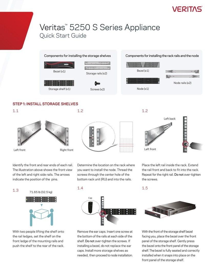
About replacing the Veritas 5U84 Storage Shelf rails
This document describes how to replace the rails for a Veritas 5U84 Storage Shelf. The rail kit
replacement requires that the storage shelf be removed from the rack.
Before you can remove the storage shelf, all programs that are running on the appliance must be
stopped. The appliance must then be shut down and then turned off.
You must remove all the hard disk drives and blanks from the storage shelf and place them on an
ESD-protective surface. Because of the extreme weight of a fully populated storage shelf, shelf
distortion may occur if the drives are left in place while the shelf is removed from the rack. Enlist two
or more people to remove the storage shelf from the rack or use a mechanical lift.
Requirements
Verify you have the following items:
• Replacement 5U84 storage shelf rail kit
• Screwdriver with a Torx T20 bit
• Removable labels with which to label components and disk drive slot locations
• Marker to write on the removable labels
• ESD-compliant wrist strap
• ESD-compliant surface
Removable components
The following components must be removed from the affected storage shelf before removing it from
the rack.
• Bezels
2
HSP 325: 5U84 Storage Shelf Rail Kit Replacement

• Disk drives in their DDIC carriers, including blanks
Note: To help facilitate access to the storage shelf, remove the door from the rack.
Prerequisites to beginning the storage shelf rail kit replacement
The compute nodes and the storage shelves need to be powered off before the starting the storage
shelf rail kit replacement.
Do the following:
•IMPORTANT: Storage shelf disk drives are installed in Disk Drive In Carrier (DDIC) mounts.
Remove all Disk Drive In Carriers with drives and blanks from the storage shelf before you begin
the storage shelf rail kit replacement process. You must label each Disk Drive In Carrier with
the exact slot location from which the Disk Drive In Carrier was removed. Each Disk Drive
3
HSP 325: 5U84 Storage Shelf Rail Kit Replacement

In Carrier must be returned to exactly the same disk drive drawer and disk drive slot once
the storage shelf is returned to the rack.
Note: Use removable labels to label the DDICs that you remove from the storage shelf disk drive
drawers.
• Remove and label all cables that are connected to the rear panel of the Storage Shelf. Label the
cables with the port from which you removed them.
Shutting down the appliance compute node and the 5U84 Storage
Shelf
Before you perform the chassis replacement service on a 5U84 Storage Shelf, all running programs
on the appliance compute node must be stopped. After all appliance programs are stopped, the
compute node and all storage shelves must be turned off.
Then the Primary shelf and any Expansion shelves must be manually turned off.
To turn off the storage shelves
1When all the compute node LEDs are off, unplug the power cords.
2Locate the on/off switches on the two power supplies on the rear of the Primary Shelf.
3Press the switch to off.
4
HSP 325: 5U84 Storage Shelf Rail Kit Replacement

4Turn off any Expansion shelves in the same manner as you turned off the Primary Shelf.
5Loosen the plastic ties from the power cords near the connections on the shelf.
6Unplug the power cords.
Removing a 5U84 Storage Shelf bezel
Use this section to remove a storage shelf bezel.
Note: There are two bezels on the 5U84 Storage Shelves. Each bezel is removed the same way.
To remove a single 5U84 Storage Shelf bezel
1Using a screw driver with a Torx T20 bit, locate and remove the four 2mm hex-head screws on
the left and right-hand sides of the bezel.
2Pull the bezel away from the front of the storage shelf drawer.
5
HSP 325: 5U84 Storage Shelf Rail Kit Replacement

Note: Set the bezels and the screws aside in a secure location to be reinstalled on the 5U84
Storage Shelf.
3Repeat the steps above to remove the other bezel.
Removing the disk drives in the 5U84 Storage Shelf
Use the following procedures to remove and label the storage shelf disk drives.
Note: Storage shelf disk drives are installed in Disk Drive in Carriers (DDIC) modules, which are
installed in numbered slots within the storage shelf disk drive drawers.
To remove the DDIC modules in the 5U84 Storage Shelf
1Put on an ESD-compliant wrist strap or take other ESD-protective measures.
2Disengage the anti-tamper locks that are located at the front of each storage shelf by using a
screwdriver with a Torx T20 bit.
3Use the screwdriver to rotate both anti-tamper locks until the arrows point towards the unlocked
padlock icons.
6
HSP 325: 5U84 Storage Shelf Rail Kit Replacement

4On the front panel of the bottom disk drive drawer, push the drawer latches inward and hold them
in. While holding them in, pull the disk drive drawer all the way out until it locks open.
Each 5U84 Storage Shelf can contain up to 84 disk drives in two drawers, which are accessible
from the front of the storage shelf. Each DDIC module within a drawer must be accurately
labeled with the slot number from which it is removed. The DDIC modules are then
re-installed in the storage shelf disk drives drawers in the exact same slots.
Use removable labels to label the DDIC modules.
If the storage shelf is half-populated with disk drives, remove the DDIC module blanks as well.
After removing each DDIC module, place the DDIC modules on an anti-static surface or place
them in anti-static bags.
7
HSP 325: 5U84 Storage Shelf Rail Kit Replacement
5Label the DDIC module with the slot numbers in which they are installed in the drive drawers.
Use the following diagram to determine the slot numbers.
6On each DDIC module, push the drive carrier latch in the direction of the arrow.
The Disk Drive In Carrier module unlocks and springs upward from the disk drive drawer.
7Pull the DDIC module upward and out of the disk drive drawer.
8Place each DDIC module in an anti-static bag or on an ESD-protective surface.
9After removing all of the DDIC modules and any blanks, close the disk drive drawer.
10 To close the drawer, press and hold the blue latches in on each side of the drawer while you push
the disk drive drawer closed..
8
HSP 325: 5U84 Storage Shelf Rail Kit Replacement
The disk drive drawer clicks when it is fully closed.
11 Use the screwdriver to rotate both anti-tamper locks until the arrows point towards the locked
padlock icons.
12 Repeat this procedure to remove the DDIC modules and blanks in the top disk drive drawer.
13 When both disk drive drawers are empty and closed, lock the disk drive drawers using the screw
driver with the Torx T20 bit.
9
HSP 325: 5U84 Storage Shelf Rail Kit Replacement
Removing all cables from the Storage Shelf
If you have not done so, remove and label all data cables from the rear of the storage shelf. Include
the port location or locations from which you remove the cables.
Do one of the following:
(5340 Appliance) To remove fiber data cables from the Fibre Channel RAID controller from a
5340 Appliance 5U84 Primary Storage Shelf:
• Remove and label all fiber cables that are connected to the SFP connectors at the rear of the
storage shelf. Label the cable with the SFP port locations on each fiber cable you remove.
You can leave the cables connected to the compute node or compute nodes, if the system is an
HA system.
Note: The color of the fiber cables may be light blue or orange.
(3340/3350/5350 Appliance) To remove the SAS3 data cables from the SAS3 Expansion ports
of the SAS3 RAID controllers in a 3340/3350/5350 Appliance 5U84 Primary Storage Shelf:
• Label and remove the SAS3 data cables that are connected to the SAS3 Expansion ports on
each of the 5U84 Primary Storage Shelf's SAS3 RAID controllers.
Warning: Note how the SAS3 cables are installed in the port before you remove it. The blue tab
should be oriented on either the top or bottom of the cable depending on the I/O module port from
which it is removed. Ensure that you orient the cables in the same manner when you reconnect
them to the I/O modules in the Primary Storage Shelf.
You can leave the cables connected to the compute nodes.
10
HSP 325: 5U84 Storage Shelf Rail Kit Replacement

(5U84 Expansion Storage Shelf) To remove SAS3 data cables from a 5U84 Expansion Storage
Shelf:
1Remove the SAS3 data cables from the Expansion Storage Shelf.
2Label the cables with the name of the ports from which you remove the cables.
Warning: Note how the SAS3 cables are installed in the port before you remove it. The blue
tab should be oriented on either the top or bottom of the cable depending on the I/O module port
from which it is removed. Ensure that you orient the cables in the same manner when you
reconnect them to the I/O modules in the Expansion Storage Shelf.
Re-installing the cables with the wrong orientation results in an inoperable storage shelf.
3Gently pull the SAS3 cable's blue tab outward to remove it from the SAS3 ports.
4Remove the power cord strain relief bale on power supply power cords.
11
HSP 325: 5U84 Storage Shelf Rail Kit Replacement

5Disconnect the power cables from both power supplies.
Removing the rail fastening screws
Use the following procedure to remove the rail fastening screws that secure the 5U84 Storage Shelf
to the rack.
To remove the rail fastening screws
1Remove the front and rear rail fastening screws from the front and rear of the rack rails.
Four clamping screws are located at the front of the 5U84 Storage Shelf rails, with two screws
on each side.
12
HSP 325: 5U84 Storage Shelf Rail Kit Replacement

2Remove the two clamping screws at the rear of the rails, with one screw on each side.
3Remove the two rear enclosure fastening screws at the rear of the rail, with one screw on each
side.
13
HSP 325: 5U84 Storage Shelf Rail Kit Replacement
Removing the 5U84 Storage Shelf from the rack
Use the following procedure to remove the 5U84 Storage Shelf from the rack.
Warning: An unpopulated 5U84 Storage Shelf can weigh up to 61.65kg (135.72lbs). Do not try to lift
it by yourself. Use two people or a mechanical lift to remove the shelf from the rack.
To remove the empty 5U84 Storage Shelf from the rack
1Using two people, slide the 5U84 Storage Shelf out from the rack.
Note: Veritas recommends using removal straps such as shown in the following image to help
move the empty storage shelf chassis from the rack.
Warning: The back end of the storage shelf is heavier than the front end.
14
HSP 325: 5U84 Storage Shelf Rail Kit Replacement

2Place the 5U84 Storage Shelf in an out-of-the-way location.
Removing 5U84 Storage Shelf rails from the rack
Use the following procedure to remove the 5U84 Storage Shelf rails from the rack.
To remove the 5U84 Storage Shelf rails from the rack
1Mark the location of the rails in the rack, if required, so the replacement rails can be installed in
the same location.
2Loosen the four middle locking screws on the inside of both the left and right-hand rails. These
screws are only accessible from the inside of the rails.
3Collapse and remove the faulty storage shelf rails from the rack. Tapping the front pins of the
rails may be needed to free the rails from the rack.
15
HSP 325: 5U84 Storage Shelf Rail Kit Replacement

4With the rails removed, inspect the rack for any damage before installing the replacement rails.
Installing a 5U84 storage shelf replacement rails
Use the following procedure to install the 5U84 Storage Shelf replacement rails in the rack.
To install the storage shelf rails
Veritas recommends that two people install the rails. One person works at the back of the rack and
one person is at the front of the rack.
A magnetic Philips-head screwdriver is required to install screws into the storage shelf rails.
1The storage shelf rails are extended to full length in the shipping container. It is easier to install
the rails when they are at their shortest length.
2Use the four adjuster screws on the inside of the rail to increase or decrease the rail length.
16
HSP 325: 5U84 Storage Shelf Rail Kit Replacement

3Identify the left and the right rails which are labeled LH (left-hand) or RH (right-hand) on the front
inside of the rail.
Note the ledge at the bottom of each rail. The storage shelf sits on the ledges which must be
positioned on the inside of the rack. The ledges must not be located between the rail and the rack
wall.
4Locate the pins on the front and the rear of the rails.
5Start with the left rail. Place the rail pins inside the front of the rack.
17
HSP 325: 5U84 Storage Shelf Rail Kit Replacement

6Extend the rail assembly to enable the rear rail pins to engage.
7Verify that the pins are fully seated in the holes in the rack posts.
8Secure the four adjuster screws as needed. Do not over-torque.
9Repeat the process for the right rail.
10 Verify that the left rails and the right rails use the same rack holes and are parallel.
11 Identify the three different types of screws.
18
HSP 325: 5U84 Storage Shelf Rail Kit Replacement

Descriptions of the screws are provided in the following table.
Rail location(s)Rack location(s)DescriptionNumber
Front: Top and bottom holes.
Rear: N/A
Front: Center holes in first
and fifth rack units (RUs).
Rear: N/A
Long fastening screw with two
washers - for use after shelf is
installed in rails.
Install the washer with the gap first.
1
Front: Center hole.
Rear: Top and bottom holes.
Front: Center hole of third
rack unit (RU).
Rear: Center holes in first
and fifth rack units (RUs).
Medium-sized clamping screw2
Front: N/A
Rear: Connects from chassis
lock tab to hole in triangular
end of rail.
Front: N/A
Rear: N/A
Small rear fastening screw3
12 Install the medium-sized clamping screws from the outside of the rack posts so that they engage
the rails and the rack.
The front of the rail requires one clamping screw in the center hole of the center RU.
The rear of the rail requires two clamping screws. Insert these screws in the middle hole in the
first and the fifth RU.
19
HSP 325: 5U84 Storage Shelf Rail Kit Replacement

Installing the rail fastening screws
Use the following procedure to install the rail fastening screws that secure the 5U84 Storage Shelf to
the rack.
To install the rail fastening screws
1Install four enclosure fastening screws in the front 5U84 Storage Shelf rails. There are two screws
on each side of the rack.
2Install the two clamping screws at the rear of the rails, with one screw on each side.
20
HSP 325: 5U84 Storage Shelf Rail Kit Replacement
Other manuals for Access 3340
8
This manual suits for next models
5
Table of contents
Other VERITAS Network Hardware manuals
Popular Network Hardware manuals by other brands

Nokia
Nokia IP60 - Security Appliance Quick setup guide

Xentino
Xentino A405N Quick installation guide

Cobalt Digital Inc
Cobalt Digital Inc BlueBox BBG-SDI-TO-IP-10GE-2022 quick start guide

ADS Technologies
ADS Technologies API-555 Software configuration guide

Huawei
Huawei RTN510 Configuration guide

Vivotek
Vivotek ND8301 Quick installation guide