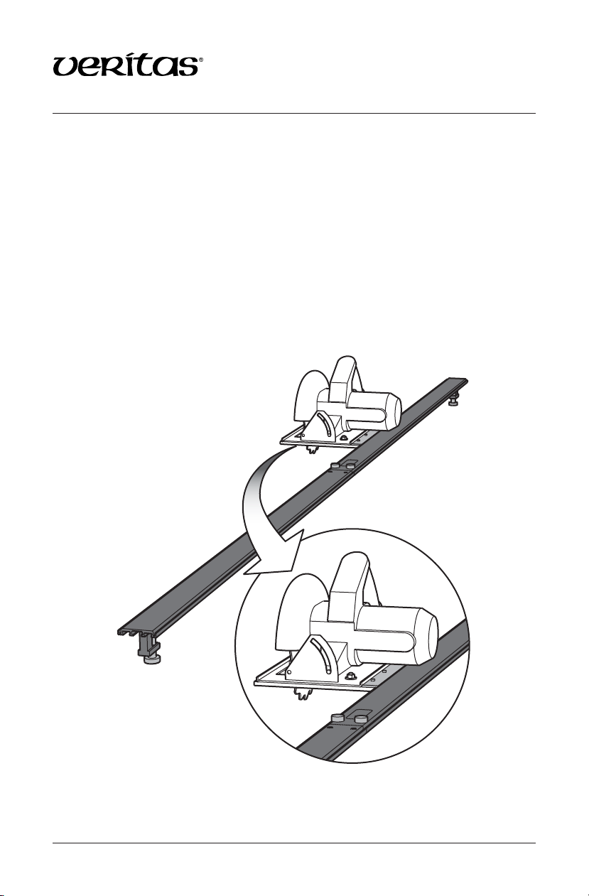
VERITAS 05J50.01 User manual

1
Power Tool Guide 05J50.01
The Veritas®Power Tool Guide is a collapsible straightedge that can be clamped to
any material under 1"thick. The 52"tool guide (05J50.03) can be clamped across
sheet material up to 52". The 8'Power Tool Guide (05J50.01), or the 48"tool guide
extension (05J50.04) added to the 52"tool guide, can be clamped across sheet
material up to 100". The advantage this guide has over other 8'guides is that it may
be dismantled quickly and easily for cutting smaller sheet material as well as for
easier storage or transport. The guide includes a pair of 1"capacity clamps that can
be positioned anywhere along its length. For clamping material thicker than plywood
sheets, a pair of 2"capacity clamps (05J50.09) is available separately. An optional 12"
traveller (05J50.02) used in conjunction with a user-made base plate ensures that your
power tool will effortlessly follow the intended line with greater safety. The utility of
the traveller is further enhanced with the optional position stop (05J50.10) that clamps
onto either guide rail.
Figure 1: Veritas Power Tool Guide.

2
Washer
broadens
as screw is
tightened.
Figure 2: Adjusting the clamp
brakes.
Figure 3: Setting the location of
the guide with a circular saw.
Cut Line
Safety Rules
These safety instructions are meant to complement those that came with your power
tool. We suggest that you reread those, in addition to these listed here before you begin
to use this product. To use this product safely, always follow both sets of safety and
general instructions.
1. Wear proper eye protection.
2. Wear proper hearing protection.
3. Remove adjusting keys before use.
4. Do not use this tool if it has been damaged in any way.
5. Clamp the workpiece firmly against the table or bench before cutting.
6. When mounting a circular saw to the traveller, make sure that the blade guard can
close properly.
7. Other than drilling mounting holes through the base plate, do not modify any
power tool in any way for use with this guide.
Set-Up
Each clamp includes a rubber washer that acts as
a brake, allowing you to place the clamps at any
location along the guide’s length, where they
will remain unless intentionally repositioned.
The rubber washers, when compressed by the
included screws, become broader, preventing
sliding. Adjust the screws such that the clamps
cannot slide down the track under their own
weight, but may be moved easily by hand. Two
spare rubber washers have been included should
they ever require replacement.
Main Guide
The main guide is 52"long and comes with the two clamps. This length allows the
guide to comfortably straddle the short (4') side of standard-sized sheet material. Mark
the cut line on the top of the sheet. Note that this does not have to be a continuous line;
it need only be marked at the near and far end.
Slide the clamps into the central T-slot, one at each
end of the beam and oriented so the open sides of
the clamp frames face each other. Place the guide
on top of the sheet, positioned so that it straddles
the sheet and is adjacent to the marks (normally
with the guide to the left of the marks), with the
clamps overhanging each end. With your power
tool unplugged and its base plate in contact with
the near edge of the guide, adjust the guide so the
tool will cut at the desired location, as illustrated
in Figure 3. Slide the clamp until it contacts the
edge of the sheet and tighten the clamp knob. Do
the same at the far end.

3
For circular saws or jigsaws, you can run the power tool in either direction along the
guide. For routers, because of the clockwise rotation of the bit, you should only run
the tool around the guide in a counterclockwise direction as shown in Figure 4. The
router will have a tendency to pull away from the guide should it be fed in the opposite
(clockwise) direction.
Tip: Recording the base plate-to-
blade (or base plate-to-bit) offset
distances of your tools will speed up the guide
alignment procedure. This will eliminate
having to awkwardly hold the power tool
against the guide while aligning the cutter
with the pencil mark on the workpiece. A
handy pictorial record of these offsets can
be affixed to your guide as shown in Figure 5.
Diagrams for circular saws, jigsaws and
routers are included on the last page of
this manual.
Tool Guide Extension
The optional tool guide extension increases
the capacity of the main guide by 4 feet,
giving a capacity of slightly more than 8 feet.
The tool guide extension is easily connected
to the main guide using the included links
and brass knobs.
Slide the links into the matching slots in the
main guide and thread both brass knobs into
the holes in the main guide. With the ends of
the guide contacting one another, firmly hand
tighten both knobs.
To break the guide down into two sections
again, you need only loosen the knobs until
the guide can be pulled apart.
...
Figure 4: Direction to run a router.
Router Label
5 1/2
Figure 5: Example of personal
power tool offset distances.
Brass Knob
Link
Main Guide
Extension Guide
Figure 6: Assembling the tool guide
extension.

4
Caution: When using the tool guide with the extension, avoid lifting the guide
from one end, as this can cause the links to break. Instead, lift the guide from the
center and place it onto your bench or workpiece.
Traveller
The traveller can greatly increase the speed, accuracy and safety of cuts made with
any power tool. The 12"traveller comes with four 1/4-20 threaded holes spaced at
3"intervals.
To use the traveller you will need to make a board onto which the traveller and the
power tool are mounted. Cut a 1/4"thick sheet of plywood or hardboard, 12"long. Its
width should be about 1"larger than the base of your power tool.
Place the traveller on top of one of the 12"
edges of the board as shown in Figure 7,
and gently hand spin a 13/64”drill bit in each of
the four holes to transfer the hole locations into
the board.
Alternatively, mark four hole locations 3"
apart, 1/2"in from the edge of the board as
shown in Figure 7.
Drill 1/4"clearance holes through the board
at the four locations and countersink the
underside so the heads of the screws do
not protrude.
Place the power tool on the board, flush with the outer edge, and mark where the
mounting holes are located and where the cutter protrudes. For circular saws, the
traveller should be on the left side of the saw. This will ensure that the weight of the
saw will be over the portion of the workpiece that does not get cut off. For routers and
jigsaws, any orientation will work.
Drill and countersink the mounting holes and make the cut in the board for the saw
blade or cutter to pass through. If you are creating a traveller for a router, and you are
familiar with plunge cutting techniques, the cut in the board may be made this way.
For a circular saw, the slot for the blade should be large enough to allow the blade
guard to operate unimpeded.
Note: Some base plates might not contain mounting holes, in which case you will have
no choice but to drill your own.
13/64"
Drill
Figure 7: Marking the hole
centers.
3"
3"
3"
1/2"

5
Affix the power tool to the board. You may need some extra hardware for this,
particular to your power tool.
To use a tool with the traveller, insert the outermost leg of the traveller extrusion into the
mating slot on the clamped guide, as shown on the front cover. Remember to account for
the base plate-to-blade (or base plate-to-bit) offset distance. Here too, the offset distance
diagrams may be helpful. Start your power tool and make the cut.
Included with your traveller is a 12"length of low-friction UHMW tape. You can
use this to line the bottom of the 1/4"board such that it slides more smoothly along
the workpiece. You may also use this to line the hook of the traveller such that it
slides more smoothly along the guide.
When using the traveller in conjunction
with a circular saw, the UHMW tape is most
effective when lining the bottom of the 1/4"
thick board. The tape should be placed on
the underside of the board between the
traveller and saw blade such that it is as far
away from the traveller as possible. The end
of the tape should be wrapped around the
leading edge of the board. Placement of the
tape is illustrated in Figure 8.
When routing, the UHMW tape is most
effective when lining the traveller hook.
Used in this way, the tape eliminates all play
between the guide and traveller and results
in very smooth operation.
To line the hook with the UHMW tape:
1. Remove the tape backing and stick it
to the inner hook of the traveller as
illustrated in Figure 9. Be sure that it is
well adhered.
2. Fold the remaining tape over the hook
and push the hook into the mating slot
in the guide. Slide the traveller back and
forth to ensure that the tape is firmly
bonded.
3. Trim off the excess.
If you find that the traveller occasionally
catches on the transition between the two
rails, sand or file the tips of all four traveller
hooks, as shown in Figure 10.
Traveller
Supplied Screws UHMW Tape
Figure 8: Mounting the traveller to a
circular saw.
12
3
Figure 9: Lining the traveller hook
with UHMW tape.
Sanded Tips
Figure 10: Modifying the traveller
hooks.

6
Position Stops
The position stops are best used
in conjunction with the traveller
to create stopped dadoes or slots.
Simply place your tool over the
starting or ending point, hook a
position stop onto a rail, slide it
over until it touches the traveller
and lock it using the brass knob.
Repeat at the opposite end of
the cut.
Power Tool Offset
Diagrams (Back Cover)
The diagrams on the back cover may be photocopied and stuck onto your guide or
power tool such that the important dimensions are always at hand. Use the series of
diagrams on the left if you are using your power tools without the traveller, or the
series on the right if you are using the traveller.
Accessories
05J50.01 100"Power Tool Guide
05J50.02 12"Traveller
05J50.03 52"Tool Guide
05J50.04 48"Tool Guide Extension
05J50.09 Pair of 2"Tool Guide Clamps
05J50.10 Tool Guide Position Stop
25U04.01 UHMW Tape, 1"× 18'
Position Stop
Position
Stop
Figure 11: Using position stops.

Veritas Tools Inc. Ottawa ON K2H 1C2 Canada veritastools.com
© Veritas Tools Inc. 2018 130 INS-153_G
Power tool offset diagrams, without traveller.
Power tool offset diagrams, with traveller.
Router
Jigsaw
Circular Saw
Router
Jigsaw
Circular Saw
Table of contents
Other VERITAS Power Tools Accessories manuals
Popular Power Tools Accessories manuals by other brands

RHEINZINK
RHEINZINK CLIPFIX 2.0 Operation, Installation, Maintenance, Spare Parts

Desoutter
Desoutter DR750-P series manual

CMT ORANGE TOOLS
CMT ORANGE TOOLS 694.021 General rules for the utilization

Forstreich Maschinenbau
Forstreich Maschinenbau TR24-AQ operating instructions

Fortum Proffesional
Fortum Proffesional 4770654 user manual

Matatakitoyo Torque Tools
Matatakitoyo Torque Tools MT2-4000N Operation manual