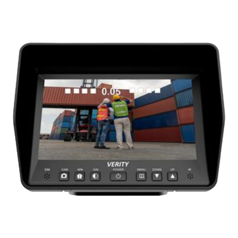
Verity Audio SM05E User manual

5 INCH DIGITAL
MONITOR SYSTEM
Part # SM05E
A division of
Component Solution Services, LLC.
56600 Twin Branch Dr.,
Mishawaka, IN 46545
www.verityrvs.com
Please read this manual completely before operating the SYSTEM
© 2016 Verity Rear Vision Systems
Just View It!®

SYSTEM FEATURES
MONITOR SPECIFICATIONS
Screen size: 5-inch digital screen (16:9)
Long Life High Resolution: 640 x 480 Pixel
(RGB)
System: NTSC
Contrast: 450:1 Brightness: 450cd/m2
Power supply: DC 12V~32V with reverse
polarity protection
Operation temperatures: -30~70C Storage
temperature: -40~80C
3 AV inputs with color coded trigger wires, auto
blue screen if no signal on activated channel
Features: sunshade, auto light sensor dimming
for LCD screen, high quality processor, in-line
fuse
Easy to use OSD menu function via buttons &
remote: reversing image delay time 0~15s,
guidelines.
1 / 3” COLOR SENSOR SPECIFICATIONS
CCD Camera, 2.9mm lens
Waterproof IP 68
6 IR Night vision
System: NTSC
Pixel: 628 X 582 RGB
View Arrange: 120°
TV line: 420

SYSTEM COMPONENTS
I/F Remote
65 foot
Camera Cable
13-pin to Monitor Cable
Manual
5-Inch HD Digital
Panel
C001E Camera

SYSTEM COMPONENTS
This monitor can be mounted on the dash and can be
mounted on both horizontal and vertical surfaces.
Make sure the view is suitable to the driver to observe
the images. Take care not to block any necessary
viewing area when mounting. Before mounting the
system, permanently hook up all connections to
ensure proper operation.
Mounting Monitor
1. After determining the monitor location, position
the monitor support bracket, mark the bolt hole
location, and then drill the holes. Be careful not to
drill into any other surface that may be hidden.
2. Attach monitor bracket. Mount the monitor to
the support bracket with supplied 4 angle adjustment
screws.
3. Connect one end of the power cable (wire) to the
proper connections. Connect the other end of the
power cable (plug) to the monitor; connect the monitor
and the camera with the 13-pin system connecting
cable.
Camera Connection
Thru-wall Gasket to Seal
Thru Vehicle Exterior
Secondary Waterproof Sleeve
Slides Over Aviation Connection
Waterproof Aviation
Connectors

MONITOR / UNVERSAL REMOTE OPERATIONS
POWER: Manual turns on monitor. Monitor will also power up
on command if a trigger wire is connected
AV:Switches between cameras
- : decreases a selected menu item
MENU: Activates operational menu (press repeatedly to move
down the options)
+ : increases selected menu item
MENU
SCROLL UP
POWER
SWITCH
CAMERA
INCREASE
DECREASE
SCROLL DOWN

CONNECTION OPERATIONS
13-Pin female
Verity Rear Vision Systems Wire Connection Key
4-pin camera connectors & trigger wires
Camera 1 rear (Brown trigger wire)
Camera 2 (Green trigger wire)
Camera 3 (Blue trigger wire)
Red wire to key-on hot (+) 10-32v. DC (fused)
Black wire to GND. (-)
Brown wire to positive Back-up light
BE SURE TO ALIGN 13 PIN CONNECTION If force
is applied to this connection when not aligned, it may
damage plug pins and void the warranty.
Female on Both
Ends
CAM 1
CAM 2
13-Pin male

MENU OPERATIONS
Press Menu: Press the (+) key to advance to the next
menu screens. Menu Screens are PICTURE, VOLUME,
OPTION, SYSTEM.
Screen 1: Depress menu repeatly to scroll down
options.
Use the (-) and (+) buttons on monitor to increase or
decrease values. Brightness, Contrast, and Color,
displayed on screen. Brightness, Contrast, and Color
have a value of 1-100 that come factory-set at 50, the mid-
range. Reset will restore the factory settings.
2 Menu Screen: VOLUME (Due to no audio on camera
this funtion has been disengaged.)
BRIGHT 50
CONTRAST 50
COLOR 50
RESET
PICTURE
PICTURE

3 PICTURE: Picture refers to picture delay. This
determines how long a camera stays on past the trigger
wire being deactivated (powered). This allows for using
the turn signal flasher wire as a trigger.
4 SYSTEM: LANGAUGE The default language is
English. There are 7 options: English, Chinese, French,
Deutsch, Italian, Spanish, and Portuguese. Source
selects the default camera. Guide lines will turn off/on
guide lines for a channel with a trigger wire connected.
5 PRESET: Sleep delays the camera function. Should
always stay set to ZERO. AV1, AV2, AV3 allows for
turning off unused channels.
CAMERA1 00S
CAMERA2 00S
CAMERA3 00S
LANG ENGLISH
SOURCE AV2
GUIDE LINES OFF
PICTURE
PICTURE
SYSTEMS:
PICTURE
SLEEP 0
AV1 ON
AV2 ON
AV3 ON
PRESET:
PICTURE

Verity Rear Vision Systems
A division of
COMPONENT SOLUTION SERVICES (CSS)
LIMITED ONE (1) YEAR WARRANTY
1. CSS products’ warranties are not transferable. The warranties
apply to the retail consumer for one (1) year and covers against
defects in material and workmanship.
2. Defective components will be replaced or repaired, based on a
CSS evaluation of the component. In-bound shipping charges, based
on the CSS rate allocated in the RMA (returned merchandise
agreement), will be covered once the component has been deemed
defective at the CSS warranty facility. The pre-assigned in-bound
freight will be supplied upon return of product. All repaired/replaced
warranty parts shall be for the remaining duration of the original
warranty time period.
3. CSS takes pride in our products and will aid in the processing of
your components:
a) All warranty claimants must have consulted our technical support
department for trouble shooting and the acquiring of an RMA.
807-6002.
b) When the warranty claim is made, the consumer must establish the
warranty start dates by presenting documentation regarding the date
of retail purchase (e.g., bill of sale). c) Service performed by non-
authorized service personnel may void all warranty claims.
d) CSS will make no payments for system removal / system re-
installing, mileage allowance, or transportation expenses.
The limited warranty does not cover damage resulting from misuse,
accident, modification or alteration to hardware or software,
tampering, unsuitable physical or operating environment beyond
product specifications, improper maintenance, or failure caused by a
product for which CSS is not responsible. There is no warranty for
any product with removed or altered identification labels. CSS DOES
NOT PROVIDE ANY OTHER WARRANTIES OF ANY KIND,
INCLUDING, BUT NOT LIMITED TO, THE IMPLIED WARRANTIES
OR CONDITIONS OF MERCHANTABILITY AND FITNESS FOR A
PARTICULAR PURPOSE. SOME JURISDICTIONS DO NOT ALLOW
THE LIMITATION OF IMPLIED WARRANTIES, SO THIS
LIMITATION MAY NOT APPLY TO YOU.
4. This warranty gives you specific legal rights, and you may also
have other rights that vary from state to state.
Table of contents
Other Verity Audio Automobile Accessories manuals