Verlinde EUROBLOC Variator VTN User manual

This document and the information contained herein, is the exclusive property of Verlinde S.A. and represents a non-public, confidential and proprietary trade secret that
may not be reproduced, disclosed to third parties, altered or otherwise employed in any manner whatsoever without the express written consent of Verlinde S.A. Copyright
© (2010) Verlinde S.A. All rights reserved.
07/2013
SUPDOC_SM_TMN0300100-0 PS20441 5.7.2013
Original instructions
EUROBLOC
®
SERVICE MANUAL FOR FREQUENCY
CONTROL SYSTEM
Variator VTN
English SUPDOC_SM_TMN030-0.ORD 5.7.2013
- - - -
159457 07.2013

GUIDE TECHNIQUE
VERLINDE se réserve le droit de modifier sans préavis les caractéristiques de
son matériel
VERLINDE reserves the right to alter or amend the above information without
notice
ADVERT TMK.DOC page1
Any modification of the acceleration or deceleration ramp which
would be too low (>2s) can damage the inverter.
Too low frequency (>10Hz) can also damage it.
Before any change, we recommend you to check the feasibility
with the factory.

EUROBLOC
®
SERVICE MANUAL FOR FREQUENCY CONTROL
SYSTEM
2/66
This document and the information contained herein, is the exclusive property of Verlinde S.A. and represents a non-public, confidential and proprietary trade secret that
may not be reproduced, disclosed to third parties, altered or otherwise employed in any manner whatsoever without the express written consent of Verlinde S.A. Copyright
© (2010) Verlinde S.A. All rights reserved.
07/2013
Table of contents
1GENERAL INTRODUCTION................................................................................................................ 4
1.1Foreword: About this manual........................................................................................................................4
1.2Symbols Used in this Manual........................................................................................................................4
1.3Safety Alert Symbols and Signal Words .......................................................................................................4
1.4Questions and Comments ............................................................................................................................5
1.5Manual Use...................................................................................................................................................5
1.6Terminology ..................................................................................................................................................6
1.7Directives and standards ..............................................................................................................................7
1.7.1CE/CSA/UL/CCC ......................................................................................................................................7
1.7.2EMC ..........................................................................................................................................................7
2SAFETY FIRST!................................................................................................................................... 9
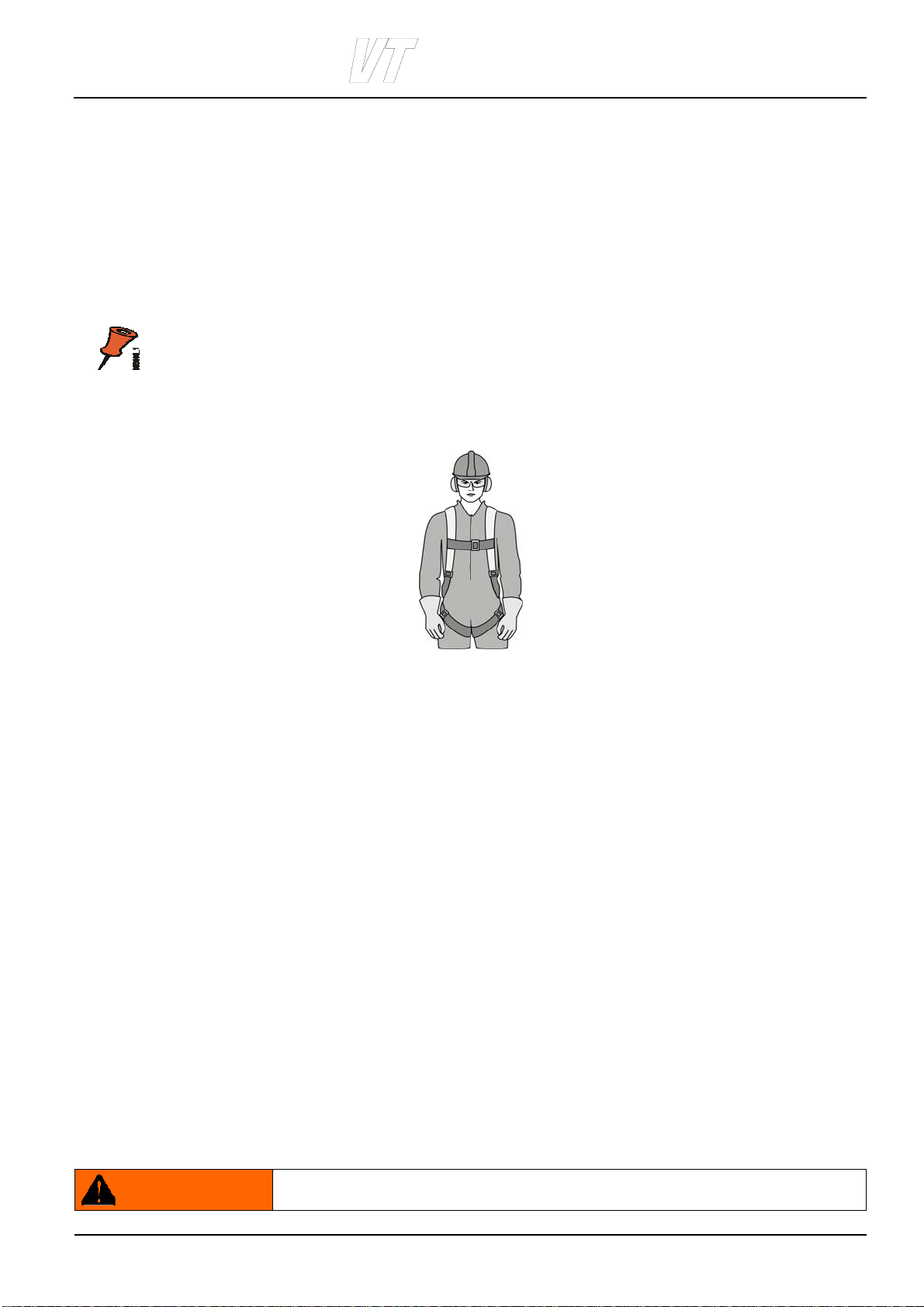
2.1Personal protective equipment (PPE)...........................................................................................................9
2.1.1Fall Protection ...........................................................................................................................................9
2.2Fire Safety.....................................................................................................................................................9
2.3Main isolation switch ...................................................................................................................................10
2.4Safety during maintenance .........................................................................................................................10
3IDENTIFICATION............................................................................................................................... 12
3.1Manufacturer...............................................................................................................................................12
3.1.1Main sticker .............................................................................................................................................12
3.2Factory code example (Factory: TMN) .......................................................................................................14
3.3Verlinde code example (Verlinde: Variator VTN, Factory: TMN)................................................................15
4CONSTRUCTION .............................................................................................................................. 16
4.1Intended use of the frequency converter ....................................................................................................16
4.2Main components........................................................................................................................................16
4.2.1Control panel...........................................................................................................................................17
4.2.2Terminal for Connection tool for TM .......................................................................................................17
4.2.3Terminals ................................................................................................................................................17
4.2.4Braking resistor .......................................................................................................................................19
4.2.5EMC Filter ...............................................................................................................................................19
5PREPREPARING THE PRODUCT FOR USE................................................................................... 21
5.1Transport and storage.................................................................................................................................21
5.2Safety precautions before installation.........................................................................................................21
5.3Mounting and installation ............................................................................................................................22
5.3.1Dimensions .............................................................................................................................................22
5.3.2Mounting .................................................................................................................................................22
5.3.3Grounding ...............................................................................................................................................23
5.3.4Model 003 with two motors .....................................................................................................................24
5.3.5Motor cable length ..................................................................................................................................24
6USER INTERFACE............................................................................................................................ 25
6.1Control panel...............................................................................................................................................25
6.2Display options............................................................................................................................................25
6.2.1Drive status .............................................................................................................................................25
6.2.2Control selection .....................................................................................................................................26
6.2.3Main menu ..............................................................................................................................................26
6.3Navigating in the menu ...............................................................................................................................27
6.3.1Using buttons ..........................................................................................................................................27
6.3.2Monitoring menu .....................................................................................................................................27
6.3.3Parameter menu .....................................................................................................................................28
6.3.4Fault history menu ..................................................................................................................................29

EUROBLOC
®
SERVICE MANUAL FOR FREQUENCY CONTROL
SYSTEM
3/66
This document and the information contained herein, is the exclusive property of Verlinde S.A. and represents a non-public, confidential and proprietary trade secret that
may not be reproduced, disclosed to third parties, altered or otherwise employed in any manner whatsoever without the express written consent of Verlinde S.A. Copyright
© (2010) Verlinde S.A. All rights reserved.
07/2013
7PARAMETERS...................................................................................................................................31
7.1General Description ....................................................................................................................................32
7.2Monitoring parameters................................................................................................................................33
7.3Parameter descriptions...............................................................................................................................34
7.3.1General parameters................................................................................................................................34
7.3.2Motor parameters....................................................................................................................................34
7.3.3Motor control parameters........................................................................................................................35
7.3.4Brake control parameters .......................................................................................................................36
7.3.5I/0 parameters.........................................................................................................................................37
7.3.6Other parameters....................................................................................................................................38
7.3.7Current control parameters.....................................................................................................................38
7.3.8System monitoring values.......................................................................................................................39
7.3.9System parameters.................................................................................................................................40
8MOTOR PARAMETER ADJUSTMENT..............................................................................................41
8.1Compact brake U/f -curve tuning values ....................................................................................................41
9FUNCTIONS.......................................................................................................................................42
9.1Auto-tuning..................................................................................................................................................42
9.2Flux braking ................................................................................................................................................43
10COMMISSIONING .........................................................................................................................44
10.1Visual checks ..............................................................................................................................................44
10.2Checks before the first run..........................................................................................................................45
10.2.1Power-up Procedure...........................................................................................................................45
10.3Test run for traveling movement without load.............................................................................................47
10.4Test run with load........................................................................................................................................48
10.5After the test run .........................................................................................................................................49
11OPERATING INSTRUCTIONS......................................................................................................50
11.1Control methods..........................................................................................................................................50
11.1.1EP (Electronic Potentiometer) control methods..................................................................................50
11.1.2Multistep control methods...................................................................................................................52
11.2Slowdown-limit ............................................................................................................................................57
11.3Stop-limit .....................................................................................................................................................57
12MAINTENANCE.............................................................................................................................58
13TROUBLESHOOTING...................................................................................................................59
13.1Problems and solutions ..............................................................................................................................59
13.2Exceptional situations .................................................................................................................................59
13.2.1Determining movement direction ........................................................................................................59
13.3Warning and Fault codes............................................................................................................................60
14TAKING PRODUCT OUT OF OPERATION ..................................................................................63
14.1Disposal of waste materials ........................................................................................................................63
15TECHNICAL DATA ........................................................................................................................64
16APPENDIX, ELECTRICAL CONNECTIONS .................................................................................65
17APPENDIX, CABLE CONNECTIONS ...........................................................................................66
17.1.1Conductor diameter and stripping lengths..........................................................................................66
17.1.2Recommended tightening torques......................................................................................................66

EUROBLOC
®
SERVICE MANUAL FOR FREQUENCY CONTROL
SYSTEM
4/66
This document and the information contained herein, is the exclusive property of Verlinde S.A. and represents a non-public, confidential and proprietary trade secret that
may not be reproduced, disclosed to third parties, altered or otherwise employed in any manner whatsoever without the express written consent of Verlinde S.A. Copyright
© (2010) Verlinde S.A. All rights reserved.
07/2013
1 GENERAL INTRODUCTION
1.1 Foreword: About this manual
This manual offers guidance to enable safe and efficient service.
Taking the time to read this manual will help you to prevent damage to the product, and, most importantly,
personnel situated close to it. The product is designed to be safe when used correctly. However, there are many
potential hazards associated with incorrect operation and these can be avoided when you know how to recognize
and anticipate them.
This manual is not intended as a substitute for proper training but provides recommendations and methods for safe
and efficient service.
1.2 Symbols Used in this Manual
Readers should familiarize themselves with the following symbols which are used in this manual.
Indicates that the product is slowing down or is moving at its slowest speed.
Indicates that the product is accelerating or moving at its highest speed.
NOTE: Indicates items which require special attention by the reader. There is no obvious risk
of injury associated with notes.
1.3 Safety Alert Symbols and Signal Words
The following symbols are used in this manual to indicate potential safety hazards.
Obey all safety messages that follow this symbol to avoid possible injury or
death.
CAUTION Indicates a potentially hazardous situation, which if not avoided, MAY result in
minor or moderate injury. It may also be used to alert against unsafe practices.
WARNING Indicates a potentially hazardous situation, which if not avoided, COULD result
in death or serious injury.
DANGER INDICATES AN IMMINENTLY HAZARDOUS SITUATION WHICH, IF NOT
AVOIDED, WILL RESULT IN DEATH OR SERIOUS INJURY.
NOTICE Addresses situations not related to personal injury, such as likely or possible damage
to equipment.

EUROBLOC
®
SERVICE MANUAL FOR FREQUENCY CONTROL
SYSTEM
5/66
This document and the information contained herein, is the exclusive property of Verlinde S.A. and represents a non-public, confidential and proprietary trade secret that
may not be reproduced, disclosed to third parties, altered or otherwise employed in any manner whatsoever without the express written consent of Verlinde S.A. Copyright
© (2010) Verlinde S.A. All rights reserved.
07/2013
Shall Indicates that a rule is mandatory and must be followed.
Should Indicates that a rule is a recommendation, the advisability of which depends on the facts in each situation.
1.4 Questions and Comments
Any questions or comments relating to the content of this manual and/or the operation, maintenance and/or service
of manufacturer products should be directed to: www.verlinde.com
1.5 Manual Use
Every person exposed to the manufacturer’s equipment must, prior to SERVICING AND/OR MAINTAINING SUCH
PRODUCTS, read and understand the contents of this manual and strictly adhere AND CONFORM THEIR
CONDUCT WITH AND TO THE INFORMATION, RECOMMENDATIONS AND warnings provided herein.
Note: Keep these instructions in a safe, accessible location for future reference by personnel operating the
equipment or exposed to the equipment’s operation.
Read and understand the contents of this manual prior to operating, servicing,
and or/maintaining the equipment. Failure to do so can result in serious injury
or death.
Manufacturer shall not be liable for and owner and READER shall release, and hold manufacturer, harmless from
any and all claims, demands, AND damages, regardless of their nature or type losses and expenses , whether
known or unknown, present or future, any and all liability, of and from any and all manner of actions, cause[s] of
actions, all suits in law, in equity, or under statute, State or Federal, of whatever kind or nature, third party actions,
including suits for contribution and/or indemnity on account of or in any way arising out of acts or omissions of the
Owner or READER and relating in any way to this MANUAL or THE PRODUCTS referenced herein, including, but
not limited to the Owner’s or READER’S use thereof or any other cause identified herein or that may be reasonably
inferred HEREFROM.

EUROBLOC
®
SERVICE MANUAL FOR FREQUENCY CONTROL
SYSTEM
6/66
This document and the information contained herein, is the exclusive property of Verlinde S.A. and represents a non-public, confidential and proprietary trade secret that
may not be reproduced, disclosed to third parties, altered or otherwise employed in any manner whatsoever without the express written consent of Verlinde S.A. Copyright
© (2010) Verlinde S.A. All rights reserved.
07/2013
1.6 Terminology
The following terms and definitions may have been used in this manual:
Authorized personnel Persons who are authorized by the owner and who have the necessary training to carry out operation or
service actions.
Braking resistor Model 006 includes an internal braking resistor for resistor braking.
Bridge The bridge (main girder) moves along the runway.
CE marking The product’s CE-marking indicates that the product complies with the appropriate CE regulations.
Check A visual and functional assessment (not a test) of the product without dismantling.
Compact brake Motor with internal brake.
Controller The pendant or other type of controller is used by the operator to give commands to the crane.
Current rating The nominal current of the frequency converter
EMC Filter The frequency converter has an internal EMC filter in the power supply
Flux braking The flux braking is a braking method in which the braking is dissipated as thermal energy in a motor. Model
003 is using flux braking as a braking method.
Hoist Drive mechanism for lifting and lowering the load.
Main girder The main girder (bridge) is connected to the bridge end carriages.
Main isolation switch The main isolation switch is the power switch which the operator should normally use to turn off the power.
Power supply Power is supplied to the components via the power supply.
Qualified personnel One with necessary qualification based on theoretical and practical knowledge of hoists or/and cranes. The
person must be in a position to assess the safety of the installation in conjunction with the application. Persons
with the authority to undertake certain maintenance work on products of manufacturers include manufacturers’
service engineers and trained fitters with corresponding certification.
Resistor braking The resistor braking is a braking method in which the braking is dissipated as thermal energy in a resistor.
Model 006 is using resistor braking as a braking method.
Slowdown limit Slowdown limit reduces the speed of the crane or trolley at the end of the runway.
Stop limit Stop limit stops the crane or trolley before the end of the runway.
Trolley (hoisting unit) The trolley (hoisting unit) moves along the main girder.
QR Code™ A two dimensional bar code that can include, for example, a product’s serial number in an optically readable
form.
Note: The term “QR Code” is a registered trademark of Denso Wave Incorporated in Japan and other
countries.

EUROBLOC
®
SERVICE MANUAL FOR FREQUENCY CONTROL
SYSTEM
7/66
This document and the information contained herein, is the exclusive property of Verlinde S.A. and represents a non-public, confidential and proprietary trade secret that
may not be reproduced, disclosed to third parties, altered or otherwise employed in any manner whatsoever without the express written consent of Verlinde S.A. Copyright
© (2010) Verlinde S.A. All rights reserved.
07/2013
1.7 Directives and standards
1.7.1 CE/CSA/UL/CCC
This product complies with one or more of the following requirements and directives described in this section. For
more detailed information about which requirements the product meets, see the main sticker attached to the
device.
CE The CE marking certifies that a product has met EU health, safety, and environmental requirements, which ensure consumer
safety.
CSA The CSA marking means that a product has been tested and meets applicable standards for safety and/or performance,
including the applicable standards written or administered by the American National Standards Institute (ANSI), Underwriters
Laboratories (UL), Canadian Standards Association (CSA), National Sanitation Foundation (NSF), and others.
UL The UL marking means that Underwriters Laboratories (UL) has tested representative samples of the product and
determined that they meet UL's requirements. These requirements are based primarily on UL's published and nationally
recognized Standards for Safety.
CCC The China Compulsory Certificate mark, commonly known as the CCC Mark, is a compulsory safety mark for a variety of
products sold on the Chinese market. The CCC mark is required for both domestically manufactured products and products
imported into China.
RoHS The RoHS marking means that a product complies with the directive for the restriction of the use of certain hazardous
substances in electrical and electronic equipment.
WEEE The WEEE indicates that the product should be disposed of according to the WEEE directive regulations.
The frequency converters carry the CE label as a proof of compliance with the Low Voltage Directive (LVD) and the
Electro Magnetic Compatibility (EMC).
1.7.2 EMC
The abbreviation "EMC" stands for Electromagnetic Compatibility. According to the European EMC directive, "the
apparatus shall be so constructed that:
yThe electromagnetic disturbance it generates does not exceed a level allowing other apparatus to operate as
intended
yThe apparatus has an adequate level of intrinsic immunity of electromagnetic disturbance to enable it to
operate as intended".
Declaration of conformity With the declaration of conformity the manufacturer informs that a device is manufactured to fulfil
required EMC standards.
Environments Immunity and emission requirements are divided in two levels in the product standard according to
the environments.
First environment is an environment that includes
domestic premises and other establishments
directly connected to a low-voltage power supply
network.

EUROBLOC
®
SERVICE MANUAL FOR FREQUENCY CONTROL
SYSTEM
8/66
This document and the information contained herein, is the exclusive property of Verlinde S.A. and represents a non-public, confidential and proprietary trade secret that
may not be reproduced, disclosed to third parties, altered or otherwise employed in any manner whatsoever without the express written consent of Verlinde S.A. Copyright
© (2010) Verlinde S.A. All rights reserved.
07/2013
Second environment is an environment that
includes all the establishments other than those
directly connected a low-voltage power supply
network.
EMC levels
There are three EMC levels: S, N and 0.
yS-level: No manufacturer’s EMC solution is adopted and products will be used in other market areas than
European Union (EU) when local power supply system is the grounded network.
yN-level: Manufacturer’s EMC solution is adopted to fit for Second Environment and products will be used in EU
when local power supply system is the grounded network.
y0-level: No manufacturer’s EMC solution is adopted, products can be used in either EU or other market areas
when local power supply system is the non grounded network.
Fulfilled EMC-standards
yImmunity: All products fulfil the immunity requirements defined in the EN61000-6-2 (2005) and the EN 61800-3
Amendment 11 (2004) for the second environment.
yEmissions: N level products fulfil the emission requirements (lower than specification) of the EN 61800-3 A11
(2004) for the second environment. 0 level products fulfil the emission requirements (they might exceed the
limit of N level products) of the EN 61800-3 A11 (2004) for the second environment.
Note: The involved products are designed for Second Environment (Industrial Environment) only. The disturbances emitting
from the basic products are not filtered to the required level of residential, commercial and light industrial (e.g. offices, gasoline
station, retailer shops etc.) environment (First Environment). In this sense, these products should not be used in First
environments. If you still want to use them in First environments, additional requirements are needed, please contact product
supplier.
Note: EMC filters in N level products might cause disturbances on residual current device (RCD).
Note: If the mains network is non-grounded (IT-network), the frequency converter’s EMC level shall be changed to 0 by
removing the filter capacitor disconnection screw.

EUROBLOC
®
SERVICE MANUAL FOR FREQUENCY CONTROL
SYSTEM
9/66
This document and the information contained herein, is the exclusive property of Verlinde S.A. and represents a non-public, confidential and proprietary trade secret that
may not be reproduced, disclosed to third parties, altered or otherwise employed in any manner whatsoever without the express written consent of Verlinde S.A. Copyright
© (2010) Verlinde S.A. All rights reserved.
07/2013
2 SAFETY FIRST!
Safety requirements must be understood and followed.
2.1 Personal protective equipment (PPE)
For safety, the service personnel or others in close proximity to the product may be required to wear Personal
Protective Equipment (PPE). Various types of PPE are available and must be selected according to the
requirements of the working environment.
Note: Follow the local regulations and requirements of the working environment.
2.1.1 Fall Protection
While personnel are performing inspection or maintenance work at heights, they must follow fall protection
procedures as required by local regulations. Fall prevention practices and fall protection equipment aim to protect
personnel working on or around the equipment from exposure to falls.
If the equipment does not have a service platform or handrail, personnel must use a properly fitted safety harness
that is attached to the dedicated fixing points on the building or equipment in order to prevent falls.
If the product does not have dedicated fixing points for fall protection, it is the owner’s responsibility to make sure
that there are suitable fixing points in the building structure.
If ladders must be used, personnel must practice setting and securing the ladders before using them for actual
work.
A typical fall protection program may include:
yDocumented and established site policies and procedures.
yConducting site assessments for fall hazards.
ySelection of the proper fall protection system and equipment.
yTraining on fall protection procedures and the proper use of fall protection systems.
yInspection and proper maintenance of fall protection equipment.
yMeasures to prevent falling objects.
yRescue Plans.
If necessary, contact your supplier or service organization for assistance with designing your fall protection
program.
2.2 Fire Safety
In the event of a fire, only attempt to fight it if you can do so without putting yourself in danger. Turn the power off if
it is possible to do so. Evacuate the area. Notify other people about the potential danger, and call for help.
WARNING Never use a powder type fire extinguisher on high voltage.

EUROBLOC
®
SERVICE MANUAL FOR FREQUENCY CONTROL
SYSTEM
10/66
This document and the information contained herein, is the exclusive property of Verlinde S.A. and represents a non-public, confidential and proprietary trade secret that
may not be reproduced, disclosed to third parties, altered or otherwise employed in any manner whatsoever without the express written consent of Verlinde S.A. Copyright
© (2010) Verlinde S.A. All rights reserved.
07/2013
2.3 Main isolation switch
CAUTION Service personnel shall be aware of main isolation switch functionality.
Eventhough one switch is turned off, there may still be voltage in some parts
of the product. This may result in exposure to electric shocks.
2.4 Safety during maintenance
Before and during product maintenance, the following precautions should be taken by maintenance personnel:
1 Choose a safe working location
The product should be moved to a location where it will cause the least disturbance and where it
can be accessed easily.
2 Prevent unauthorized access to the site
Prevent unauthorized persons and bystanders from walking on or below the work site. For
example, you can lock doors, install barriers and display notices.
Ensure that the secured area is spacious enough to prevent injuries which could occur as a result
of falling components or tools.
3 Inform that equipment will be undergoing maintenance
Before starting maintenance, people must be properly informed that the equipment is being
removed from operation.
4 Ensure that there is no load on the lifting device
Before starting maintenance there should be no load on the hook or lifting device.
Park the hook on the ground if there is any chance that the hoisting brake will be opened during
maintenance. A raised empty hook will fall to the ground if the hoisting brake is opened.
5 Turn all controllers and main switches off
All controllers and main isolation switches must be placed in the off position before starting
maintenance.
6 Lockout – Tagout
The product power source must be locked out and tagged out when necessary, in accordance with
local regulations. See chapter “Lockout – Tagout Procedure”

EUROBLOC
®
SERVICE MANUAL FOR FREQUENCY CONTROL
SYSTEM
11/66
This document and the information contained herein, is the exclusive property of Verlinde S.A. and represents a non-public, confidential and proprietary trade secret that
may not be reproduced, disclosed to third parties, altered or otherwise employed in any manner whatsoever without the express written consent of Verlinde S.A. Copyright
© (2010) Verlinde S.A. All rights reserved.
07/2013
7 Verify that power is completely disconnected
Measure between the phases and between each phase to ground to ensure that power is
completely disconnected from the product.
8 Use hand lines for lifting and lowering tools
Hand lines, securely attached to the building structure, should be used for lifting or lowering
materials and tools. Use proper safety equipment to prevent objects from falling when working in
high places.
9 Safety devices must be restored to operational status
Ensure that any safety devices which have been bypassed for testing purposes have been
restored to full operational status before allowing the product to be used for normal operation.
10 Minimize the risks of moving machinery
Secure the area so that personnel are not at risk from the movements of machines, automatic
doors or adjacent cranes at the installation site.
Ensure that machinery and equipment cannot start up accidentally and cannot move during
installation and servicing.
Be prepared in case equipment moves in the wrong direction during testing.
11 Perform regular inspections and preventive maintenance
To ensure ongoing safe and efficient operation of the product, carry out regular inspections and
preventive maintenance in compliance with the instructions. Keep a record of all inspections and
servicing. If in doubt, contact the supplier of the product.

EUROBLOC
®
SERVICE MANUAL FOR FREQUENCY CONTROL
SYSTEM
12/66
This document and the information contained herein, is the exclusive property of Verlinde S.A. and represents a non-public, confidential and proprietary trade secret that
may not be reproduced, disclosed to third parties, altered or otherwise employed in any manner whatsoever without the express written consent of Verlinde S.A. Copyright
© (2010) Verlinde S.A. All rights reserved.
07/2013
3 IDENTIFICATION
3.1 Manufacturer
Manufacturer:
V
erlinde S.A.
2, Boulevard de l'Industrie
BP 20059
28509 VERNOUILLET CEDEX
FRANCE
Address:
Note: For further information about the product, operational training or servicing, please contact the
manufacturer or manufacturer’s representative.
3.1.1 Main sticker
The main sticker shows, for example, the model and serial number of the frequency converter, as well as the rated
voltage.
1 Product model number Indicates the exact model of the product.
2 Identification number A unique string that identifies the unit.
3 Input Indicates the acceptable mains voltage range, current and frequency that the product can be
connected to.
4 Output Indicates the voltage range, current and frequency range the product is able to provide at a
specified output capacity.
5 Control Indicates the acceptable voltage range and frequency of control signals that the product can
be connected to.
6 Serial number The serial number of the unit in an alphanumerical format.
7 IP classification Indicates the ingress protection classification of the product.
8 EMC level modified Indicates whether the EMC level has been changed from the default level. By default, the
EMC level is set as N. See chapter “EMC” for more information of EMC levels.
9 Option board Indicates whether the product is fitted with an optional board providing additional features.
Option boards can be used only with a frequency converter featuring a display. Not in use in
this frequency converter.

EUROBLOC
®
SERVICE MANUAL FOR FREQUENCY CONTROL
SYSTEM
13/66
This document and the information contained herein, is the exclusive property of Verlinde S.A. and represents a non-public, confidential and proprietary trade secret that
may not be reproduced, disclosed to third parties, altered or otherwise employed in any manner whatsoever without the express written consent of Verlinde S.A. Copyright
© (2010) Verlinde S.A. All rights reserved.
07/2013
10 Approvals and standards Indicates the directives and approvals the product complies to. See the section “Directives
and standards” for more information.
11 Batch identification number Indicates the batch from which the unit originates. The first four digits indicate the year and
week of manufacture, respectively. The last digit (1 through 5) indicate the weekday, 1 being
Monday, 2 Tuesday, number 5 indicating Friday.
12 Code Identification and feature information provided by the manufacturer.
13 QR Code™ A two dimensional bar code in an optically readable form.
Note: The term “QR Code” is a registered trademark of Denso Wave Incorporated in Japan
and other countries.

EUROBLOC
®
SERVICE MANUAL FOR FREQUENCY CONTROL
SYSTEM
14/66
This document and the information contained herein, is the exclusive property of Verlinde S.A. and represents a non-public, confidential and proprietary trade secret that
may not be reproduced, disclosed to third parties, altered or otherwise employed in any manner whatsoever without the express written consent of Verlinde S.A. Copyright
© (2010) Verlinde S.A. All rights reserved.
07/2013
3.2 Factory code example (Factory: TMN)
TM N 003 E 0 10 0 W M M
(TR01)(BT01) (TR01)(BT01) (ELE84)(ELE85) (ELE84)(ELE85) (ELE02)
1,2 3 4-6 7 8 9,10 11 12 13 14
Pos. Code Feature
code Feature Available properties
1,2 TM (TR01)
(BT01) Device name TR/BT01 value TR01 Type of trolley travel control
BT01 Type of bridge travel control
TM Traveling model TMN
3 N (TR01)
(BT01) Interface model Model type
N Display model
4-6 003 (ELE84)
(ELE85) Power rating class 003, 006 ELE84 Trolley travel inverter power rating
ELE85 Bridge travel inverter power rating
Values are composed of two features,
Power rating class and Supply voltage.
e.g. 006E = ELE84/ELE85 value
7 E (ELE84)
(ELE85) Supply voltage E
J
380 – 480 VAC, 50/60 Hz
208 – 240 VAC, 50/60 Hz
8 0 (ELE02) Control voltage 0 48 – 230 VAC, 50/60 Hz ELE02 Control voltage for digital input
9,10 10 Revision code The latest revision may differ.
11 0 Braking resistor type
0
B
No resistor (only 003)
Braking resistor (only 006)
12 W Mounting W Wall mounting
13 M EMC level and grounding M Modifiable
14 M Option board M Modifiable

EUROBLOC
®
SERVICE MANUAL FOR FREQUENCY CONTROL
SYSTEM
15/66
This document and the information contained herein, is the exclusive property of Verlinde S.A. and represents a non-public, confidential and proprietary trade secret that
may not be reproduced, disclosed to third parties, altered or otherwise employed in any manner whatsoever without the express written consent of Verlinde S.A. Copyright
© (2010) Verlinde S.A. All rights reserved.
07/2013
3.3 Verlinde code example (Verlinde: Variator VTN, Factory: TMN)
Variator VTN 003 E 0 10 0 W M M
(TR01)(BT01) (ELE84)(ELE85) (ELE84)(ELE85) (ELE02)
1-12 13-15 16 17 18,19 20 21 22 23
Pos. Code Feature
code Feature Available properties
1-12 Variator VTN (TR01)
(BT01) Device name TR/BT01 value TR01 Type of trolley travel control
BT01 Type of bridge travel control
Variator VTN Traveling model TMN
13-15 003 (ELE84)
(ELE85) Power rating class 003, 006 ELE84 Trolley travel inverter power rating
ELE85 Bridge travel inverter power rating
Values are composed of two features,
Power rating class and Supply voltage.
e.g. 006E = ELE84/ELE85 value
16 E (ELE84)
(ELE85) Supply voltage E
J
380 – 480 VAC, 50/60 Hz
208 – 240 VAC, 50/60 Hz
17 0 (ELE02) Control voltage 0 48 – 230 VAC, 50/60 Hz ELE02 Control voltage for digital input
18,19 10 Revision code The latest revision may differ.
20 0 Braking resistor
type
0
B
No resistor (only 003)
Braking resistor (only 006)
21 W Mounting W Wall mounting
22 M EMC level and
grounding M Modifiable
23 M Option board M Modifiable

EUROBLOC
®
SERVICE MANUAL FOR FREQUENCY CONTROL
SYSTEM
16/66
This document and the information contained herein, is the exclusive property of Verlinde S.A. and represents a non-public, confidential and proprietary trade secret that
may not be reproduced, disclosed to third parties, altered or otherwise employed in any manner whatsoever without the express written consent of Verlinde S.A. Copyright
© (2010) Verlinde S.A. All rights reserved.
07/2013
4 CONSTRUCTION
4.1 Intended use of the frequency converter
This manual covers the installation and use of frequency converter model with display.
These frequency converters are designed for industrial crane usage to control the speed of trolley and bridge
movements.
Note: The frequency converter shall be used only in crane applications.
Note: Only the product’s manufacturer shall perform any voltage withstand tests.
Any alterations and/or modifications to the product not authorized by the manufacturer are strictly
prohibited. Opening the product’s cover voids its warranty.
4.2 Main components
The 003 model The 006 model
Pos. Part Description
1 Display LCD Display
2 Navigation and
confirmation buttons
Buttons with four arrow navigation buttons and buttons for back/reset and confirmation, used in navigating
in the menu structure and in adjusting parameter values.
3 Terminal for MCA cable MCA cable is used with Connection tool for TM.
4 Main sticker Identification data
5 EMC fIlter screw EMC level of the frequency converter can be modified by removing the EMC filter screw
6 Power supply terminals 3-phase power supply and motor supply terminals
7 Digital input terminals 6 digital input terminals (API2 control board)
8 Braking resistor Internal braking resistor (in model 006)

EUROBLOC
®
SERVICE MANUAL FOR FREQUENCY CONTROL
SYSTEM
17/66
This document and the information contained herein, is the exclusive property of Verlinde S.A. and represents a non-public, confidential and proprietary trade secret that
may not be reproduced, disclosed to third parties, altered or otherwise employed in any manner whatsoever without the express written consent of Verlinde S.A. Copyright
© (2010) Verlinde S.A. All rights reserved.
07/2013
4.2.1 Control panel
The control panel contains:
yLCD display with backlight.
yDisplay options (1-3) indicating drive status, control selection and current menu.
yButtons (4-5) with four arrow navigation buttons and buttons for back/reset and confirmation, used in navigating
in the menu structure and in adjusting parameter values.
1 – Drive status
2 – Control indication
3 – Main menu
4 – Back/Reset button
5 – Navigation and confirmation (OK) buttons
See chapter “User interface” for more detailed information of display options and navigating in the menu.
4.2.2 Terminal for Connection tool for TM
Micro Communication Adapter (MCA) can be plugged into this terminal. MCA is used when establishing connection
to frequency converter with laptop and USB through RS-485 cable.
4.2.3 Terminals
WARNING To avoid an electrical shock, the mains supply shall be disconnected. Before
working on the frequency converter’s terminals, wait at least 5 minutes after
the cooling fan has stopped and indicators have switched off.
The frequency converter power module has terminals for 3-phase power supply and 3-phase motor supply.
Frequency converters of the higher current rating also have terminals for an external braking resistor.
The connection terminals of the 003 model The connection terminals of the 006 model

EUROBLOC
®
SERVICE MANUAL FOR FREQUENCY CONTROL
SYSTEM
18/66
This document and the information contained herein, is the exclusive property of Verlinde S.A. and represents a non-public, confidential and proprietary trade secret that
may not be reproduced, disclosed to third parties, altered or otherwise employed in any manner whatsoever without the express written consent of Verlinde S.A. Copyright
© (2010) Verlinde S.A. All rights reserved.
07/2013
All models have 6 digital inputs. In addition, there is one relay connection which can be used to, for example,
control a brake.
The control voltage for digital inputs can be 42 – 240VAC. All digital inputs must be connected to same control
voltage transformer.
The transformer shall have galvanically separated windings and the neutral phase of the secondary circuit must be
connected to protective earth.
The frequency converter has protection against earth faults in the motor or in the motor cables. Since the frequency
converter has a plastic cover, it does not ground via the DIN rail.
Digital inputs DI1 and DI2 are always direction commands, which functions can not be changed. The functions of
inputs DI3 – DI6 vary depending on parameter settings.
There are also encoder inputs, analog inputs, strain gauge sensor inputs and CAN bus inputs including
corresponding power supplies. All terminals are listed in the table below.
The digital input terminals on all models
Terminal / Name Function Cable size
mm2 AWG
Power
module
L1
3-phase input
1.5 – 4.0 16 – 12
L2
L3
U / T1
Motor output
V / T2
W / T3
R+ R- External braking resistor (no in model 003)
PE Protective earth
Control
board
1 DI1 Drive command forward
1.0 – 2.5
20 – 10
2 DI2 Drive command reverse
3
4
5
DI3
DI4
DI5 Function depends on parameter settings
6 DI6 Motor temperature protection / External stop
7 COM Common DI1-DI6
8 ROA1 out Normally open relay output
9 ROA1 in

EUROBLOC
®
SERVICE MANUAL FOR FREQUENCY CONTROL
SYSTEM
19/66
This document and the information contained herein, is the exclusive property of Verlinde S.A. and represents a non-public, confidential and proprietary trade secret that
may not be reproduced, disclosed to third parties, altered or otherwise employed in any manner whatsoever without the express written consent of Verlinde S.A. Copyright
© (2010) Verlinde S.A. All rights reserved.
07/2013
DANGER
THE MOTOR TERMINALS (U, V, W / T1, T2, T3) AND BRAKING RESISTOR
TERMINALS (R+ AND R- WHEN APPLICABLE) ARE LIVE WHEN THE
FREQUENCY CONVERTER IS CONNECTED TO A MAINS SUPPLY, EVEN WHEN
THE MOTOR IS NOT RUNNING. THE CONTROL BOARD’S RELAY OUTPUT
TERMINALS (WHEN APPLICABLE) MAY HAVE A DANGEROUS CONTROL
VOLTAGE, EVEN WHEN THE FREQUENCY CONVERTER IS DISCONNECTED
FROM THE MAINS SUPPLY. THESE CONDITIONS MAKE A RISK OF
ELECTRICAL SHOCK POSSIBLE.
WARNING The RCD current from the frequency converter can exceed 3.5mA AC.
According to standard EN61800-5-1, a reinforced protective ground connection
shall be ensured to reduce the risk of an electrical shock.
4.2.4 Braking resistor
For resistor braking model 006 includes an internal braking resistor. Resistance of the internal braking resistor is
120 ohm (45W). The resistor braking is a braking method in which the braking energy is dissipated as thermal
energy in a resistor.
It is also possible to use external braking resistor with the model 006. External braking resistor used is
DMHR01F90 with resistance 90 ohm (550 W) or RK02-1200W1150 with resistance 115 ohm (1.2 kW).
Resistor type Power class Resistance (ohm) Used with TMN
Internal plate resistor 45W 120 006
DMHR01F90 550 W 90 006
RK02-1200W1150 1.2 kW 115 006
Note: Model 003 does not have an external braking resistor.
4.2.5 EMC Filter
The frequency converter has an internal EMC filter in the power supply. By default, the EMC level of the frequency
converter is set to N by the manufacturer.
If the mains network is non-grounded (IT-network), the frequency converter’s EMC level shall be changed to 0 by
removing the filter capacitor disconnection screw.
NOTICE The frequency converter will be irreparably damaged if it is connected to an IT
network before the filter capacitor disconnection screw is removed.
Table of contents
Popular Control System manuals by other brands

Intelitek
Intelitek Dual Axis Vise Accessory installation guide

eqss
eqss OverWatch 6253 installation manual

Crestron
Crestron TPCS-4SM Configuration guide

Siemens
Siemens SINUMERIK 840D sl Upgrade instructions

WattMaster
WattMaster Water Source Heat Pump Installation & operation manual

Elsner
Elsner WS1 Color manual