Verlinde CHD User manual

VERLINDE reserves the right to alter or amend the above information without notice.
02/2010
CHD
CHD CHD
CHD -
--
-
CHDD
CHDDCHDD
CHDD
-
-
-
English
-
-
-
DOCKHVBLA4-0.ORD
-

-
--
-
2
VERLINDE reserves the right to alter or amend the above information without notice. 02/2010
DOCKHVBLA40100-0 PS09078 11.2.2010
This document is a copy.
Read the instructions supplied with the product before installation and commissioning.
Keep the instructions in a safe place for future reference.
Table of content
CHD - CHDD ....................................................................................................................... 1
1 Manual trolleys .......................................................................................................... 3
1.1 Guarantee ...........................................................................................................................3
1.2 What not to do.....................................................................................................................4
1.3 What to do ...........................................................................................................................4
1.4 General ................................................................................................................................5
1.4.1 Acceptance of the material........................................................................................5
1.4.2 Installation......................................................................................................................5
1.5 Presentation .........................................................................................................................7
1.5.1 Brief description of manual gantry crab .....................................................................7
1.5.2 Characteristics – Dimensions ........................................................................................7
1.6 Setting of the axle "no rock"..............................................................................................11
1.7 Adjustment of the flanges.................................................................................................12
1.8 Assembly on the track.......................................................................................................13

-
--
-
3
VERLINDE reserves the right to alter or amend the above information without notice. 02/2010
1
11
1Manual trolleys
Manual trolleysManual trolleys
Manual trolleys
1.1
1.11.1
1.1
Guarantee
GuaranteeGuarantee
Guarantee
WARNING
The company reserves the right to modify or improve the material described below
and, in this case, to supply it different to the illustrations or specifications in this
manual.
Our equipment is guaranteed for a period of 1 year from the date of delivery for
manually-operated equipment.
If delivery is delayed for a reason beyond the control of the seller, the difference in date
cannot be in excess of 3 months.
If the utilization (installation) of the equipment is delayed, the extension of the guarantee
is limited to 3 months, non-cumulative, to be requested with written agreement.
The seller undertakes to remedy any operating vice resulting from a fault in the design, or
implementation, or the components or the materials themselves.
The guarantee does not cover wear and tear*, nor accidents resulting from a lack of
regular and periodical upkeep, it does not cover deterioration due to a lack of
surveillance, incorrect manipulations or poor operation of the equipment, in particular
overloading, pulling sideways.
The guarantee does not apply each time dismantling, modification or changing of parts is
carried out without our agreement or by a non-authorized agent.
The guarantee only applies to original spare parts from the constructor including lifting
chains.
During the guarantee period, the seller must, free of charge, replace or repair parts
recognized as defective after examination by his qualified and authorized engineering
department.
The guarantee excludes all other payment or compensation. Under the guarantee, the
repairs are in principle carried out into the workshops of the seller or his agent authorized
by the constructor. When work is carried out on the material outside these workshops, the
manpower costs related to the dismantling or reassembly of these parts are borne by the
seller when these operations are carried out solely by his staff or an agent authorized by
the constructor. The replaced parts become the property of the seller and must be
returned to him at his charge.
For components of special relative importance and not manufactured by the seller
himself, and which carry the trademark of specialized constructors, the guarantee, which
can vary depending on the constructor, is that which is issued by the latter.
* The guarantee does not apply to wearing parts defined by the constructor, see the
following list:
•Travelling chain,

-
--
-
4
VERLINDE reserves the right to alter or amend the above information without notice. 02/2010
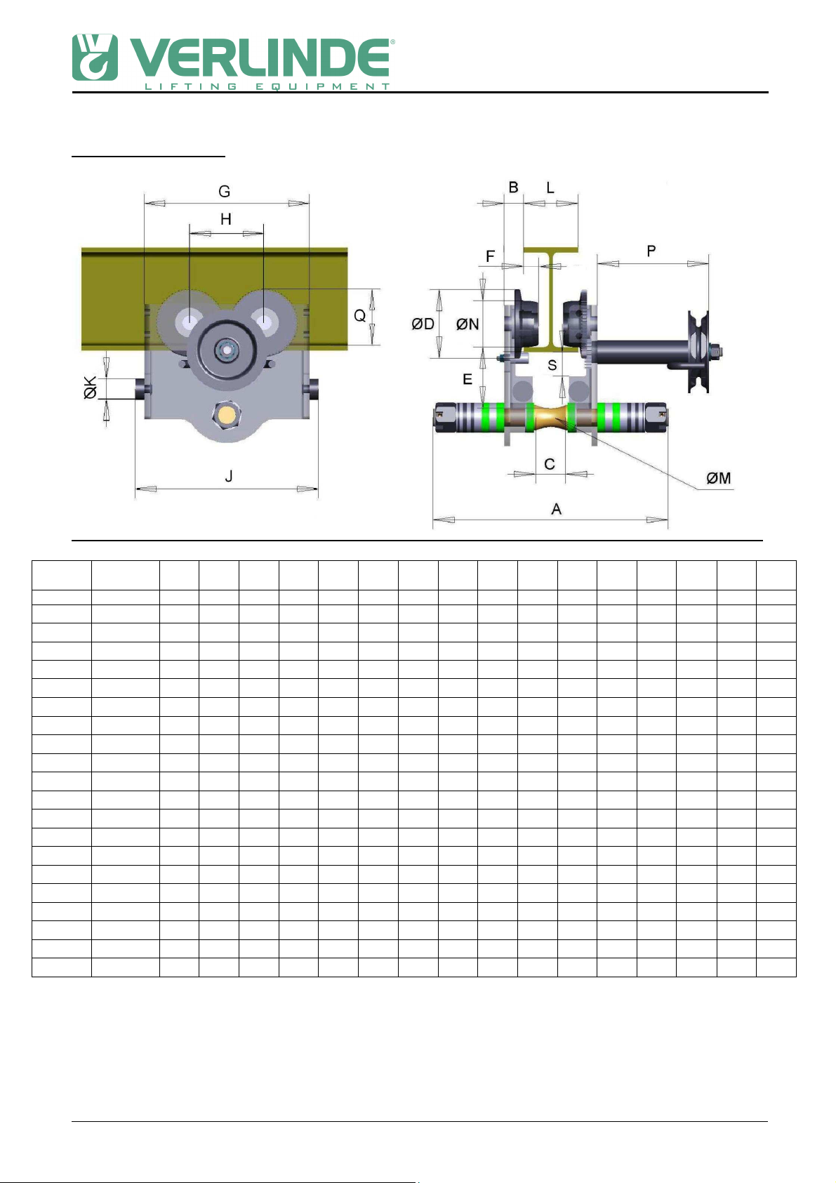
•Travelling hand wheel,
•Coupling part or traversing parts,
•Travelling wheels,
1.2
1.21.2
1.2
What not to do
What not to doWhat not to do
What not to do
Do not set down the machine without having an adapted support, to avoid damaging the
sensitive sides.
Do not let the machine drop.
Never modify the machine unless the constructor has studied and authorized the
modification.
Never modify the values and adjustments of the safety components, outside the limits
provided for in the manual, or without the approval of the constructor.
Never try to repair or intervene on the machine (welding...) without the authorization of the
constructor or a trained maintenance agent.
Do not let an unqualified person use the machine.
Never lift more than the maximum working load indicated on the machine. Shocks or
accidental collision of the load with objects can cause excess loads.
Never remove the hook safety catches.
Never use the machine to extract, loosen, or pull sideways.
Never use the machine to transport people.
Do not touch the moving components.
Do not operate the machine if your physical condition does not allow it.
Never use the machine when in bad repair (wear, deformation...).
Never use suspect spare parts or parts whose origin is not known.
Never swing the load intentionally.
Do not subject the machine to brutal shocks.
Do not use the mechanical stops as a repetitive means of stopping.
Never distract the operator while the machine is being operated.
Never leave a suspended load hanging, if it is not necessary
Do not use the machine for a purpose or in an area for which it is not intended.
Do not expose the machine to an aggressive atmosphere (temperature, acidity..).
Do not use the safety components as operation components.
Do not use the controls needlessly (avoid inching - stop-start operation of the buttons). This
can cause overheating and even damage to the machine.
Never pull the load slantwise. Make sure that the machine is vertical to the load before lifting
it.
Never transport a load with people nearby. Do not pass the machine, with or without a load,
above a person.
1.3
1.31.3
1.3
What to do
What to doWhat to do
What to do
Handle the machine by its structure, or by the devices provided for this purpose, or in its
original packing.
Store the machine in its normal operating position (without load) away from aggressive
atmospheres (dust, humidity...).
Make sure that the machine is always clean and protected from corrosion (lubrication...).
The machine should be installed by a technician with the necessary competence.
Make sure that the machine attaching structure is rigid.
Make sure that the safety rules are followed (harness, clearance of work areas, posting up of
instructions to be followed in the area...).
Use the trolley between –10°C and + 50°C.

-
--
-
5
VERLINDE reserves the right to alter or amend the above information without notice. 02/2010
Comply with the distance between the trolley and the raceway.
Connect the feed cable directly to the supply terminal board in the electric box.
Set up an inspection program and record all of the maintenance operation for the
machines, in particular: the brake, limit switches, fastening beam...
Replace any element that is worn or may be defective.
The machine should be maintained regularly, following the instructions in this manual.
Check the operation and adjustment of the safety components (brake, travel limit...) in
conformity with the user manual.
Regularly check the machine.
If a deformation or unusual wear is noted, the parts must be changed.
Check that the assembly elements are correctly tightened.
Check that the strands of the steel cable supporting the control box fulfill their functions
correctly.
The components should only be replaced by original parts that are compatible with the
type of machine.
Before operation, check that the load is correctly fastened and installed. Make sure that the
load is correctly balanced before moving it. Pay attention to the center of gravity of the
load to be moved.
When moving the load, make sure that it is sufficiently raised and distant from the
surrounding machines and other objects so as to avoid all obstacles during operation, ask
for some help if the volume of the load prevent from seeing above it.
Use the standards of ergonomics to use the trolley.
If manually moving the machine, push the load.
The prevention instructions to be carried out during the different operations should be well
known.
Use the material under normal working conditions (ambient temperature, atmosphere...).
Material used outdoors should be protected as well as possible against bad weather
conditions.
Notify the necessary people after a dangerous operation or if the machine seems
problematic (abnormal noise, abnormal behaviour...).
1.4
1.41.4
1.4
General
GeneralGeneral
General
1.4.1 Acceptance of the material
Carry out a visual inspection of the packing to ensure
that it is intact.
If it is not, issue the appropriate notifications.
Check that the trolley corresponds to your order.
1.4.2 Installation
The service life of a trolley depends on the way in which it is installed.
It is essential that the instructions in this manual are followed carefully for the installation, use,
and maintenance of your machine.
Any use contrary to our instructions may be dangerous. In this case, the manufacturer will not
accept any liability.
Do not use the machine without having read and understood the whole of the instruction
manual.

-
--
-
6
VERLINDE reserves the right to alter or amend the above information without notice. 02/2010
Always keep the manual close to the machine, available to the operator and to the person
responsible for maintenance.
Make sure that the safety rules are followed (harness, clearance of work area, posting of
instructions to be followed in the work area, etc.).
The trolley can be adapted to all runaway profiles. Couple or hook on the hoist after installation
of the trolley.
CAUTION ! Check the width of the runaway rail and adapt the spacing
of the flanges of the trolley as indicated in the tables
Make sure:
•That the profile is secured.
•That the profile is suitable to the loads to be supported.
•That the dimensions are compatible with the trolley which is to be installed.
•that the maximal deflection of the profile do not exceed 1/500 of the span under the
dead loads and the SWL.
•that the longitudinal slope of the track do not exceed 0.3 %.
Carry out:
1 – Disassembly of the trolley
•Remove the side plate on the counterweight side
•Position the trolley on the beam
•Refit the side plate.
•Check that all the nuts are correctly tightened.
2 – Without disassembly of the trolley
•Install the trolley on the profile, by the end
•Fit the travel limit stops (not provided) at the end of the runway.
•Check that all the nuts are correctly tightened.

-
--
-
7
VERLINDE reserves the right to alter or amend the above information without notice. 02/2010
On the curved profiles, the driving wheels should for
preference be positioned on the outside of the curve.
These points have to be checked a repair, a maintenance operation or a long stop.
Curve radius : 250 kg / 500 kg = 1 meter
1000 kg = 1,5 meter
2000 kg / 3000 kg = 2 meters
5000 kg = 3 meters
Note : Coupling part center must be located in the center of the beam.
1.5
1.51.5
1.5
Presentation
PresentationPresentation
Presentation
The manual gantry crabs make it possible to suspend any type of lifting equipment provided
with a hook, lifting loads of 250 to 10,000 kg.
1.5.1 Brief description of manual gantry crab
The crab is comprised of :
•2 flanges, in sheet steel,
•4 rollers mounted on ball bearings with detachable axles and rolling rims profiled to roll
on any type of iron monorail,
•1 cross-bar for hook or coupling, in steel, ensure the bracing of the assembly.
1.5.2 Characteristics – Dimensions
VERY IMPORTANT!
See side plate setting table

-
--
-
8
VERLINDE reserves the right to alter or amend the above information without notice. 02/2010
Push travel trolley
Capacity Beam width A B C ØD E F G H J ØK ØM ØN
( Kg ) ( mm ) mm mm mm mm mm mm mm mm mm mm mm mm
250 50 - 202 284 16 32 74 60 13 170 80 194 18 15 50
500 50 - 200 303 19 32 79 62 19 185 85 210 24 20 55
188 - 310 411 19 32 79 62 19 185 85 210 24 20 55
1000 65 - 202 326 22 39 92 82 22 225 101 249 28 22 62
188 - 310 425 22 39 92 82 22 225 101 249 28 22 62
2000 88 - 202 340 26 42 104 98 24 272 124 296 36 28 76
188 - 310 448 26 42 104 98 24 272 124 296 36 28 76
3000 100 - 202 356 28 49 131 146 27 322 145 346 44 28 96
188 - 310 464 28 49 131 146 27 322 145 346 44 28 96
5000 114 - 202 375 34 60 144 161 36 362 158 386 48 35 108
188 - 310 484 34 60 144 161 36 362 158 386 48 35 108
6300 124 - 202 394 43 68 170 175 39 411 185 436 50 43 130
188 - 310 502 43 68 170 175 39 411 185 436 50 43 130
7500 124 - 202 394 43 68 170 175 39 411 185 436 50 43 130
188 - 310 502 43 68 170 175 39 411 185 436 50 43 130
10000 124 - 202 400 46 70 176 187 40 442 200 466 50 45 134
188 - 310 506 46 70 176 187 40 442 200 466 50 45 134
12500 124 - 202 408 48 70 176 185 41 442 200 466 50 50 134
188 - 310 514 48 70 176 185 41 442 200 466 50 50 134
16000 136 - 202 472 75 92 226 283 54 555 272 579 50 64 168
188 - 310 578 75 92 226 283 54 555 272 579 50 64 168
20000 136 - 202 472 75 88 226 277 54 555 272 579 50 68 175
188 - 310 578 75 88 226 277 54 555 272 579 50 68 175

-
--
-
9
VERLINDE reserves the right to alter or amend the above information without notice. 02/2010
Chain travel trolley
Capacity Beam
width A B C ØD E F G H J ØK ØM ØN P Q S U
(Kg) (mm) mm mm mm mm mm mm mm mm mm mm mm mm mm mm mm mm
1000 65 - 202 326 22 39 92 82 22 225 101 249 28 22 62 146 76 40 160
188 - 310 425 22 39 92 82 22 225 101 249 28 22 62 146 76 40 160
2000 88 - 202 340 26 42 104 98 24 272 124 296 36 28 76 146 92 38 157
188 - 310 448 26 42 104 98 24 272 124 296 36 28 76 146 92 38 157
3000 100 - 202 310 28 49 131 146 27 322 145 346 44 28 96 37.5 114 38 58
188 - 310 418 28 49 131 146 27 322 145 346 44 28 96 37.5 114 38 58
5000 114 - 202 326 34 60 144 161 36 362 158 386 48 35 108 37.5 126 47 60
188 - 310 434 34 60 144 161 36 362 158 386 48 35 108 37.5 126 47 60
6300 124 - 202 344 43 68 170 175 39 411 185 436 50 43 130 80 154 46 68
188 - 310 452 43 68 170 175 39 411 185 436 50 43 130 80 154 46 68
7500 124 - 202 344 43 68 170 175 39 411 185 436 50 43 130 80 154 46 68
188 - 310 452 43 68 170 175 39 411 185 436 50 43 130 80 154 46 68
10000 124 - 202 350 46 70 176 187 40 442 200 466 50 45 134 80 154 46 68
188 - 310 458 46 70 176 187 40 442 200 466 50 45 134 80 154 46 68
12500 124 - 202 358 48 70 176 185 41 442 200 466 50 50 134 59 154 45 65
188 - 310 466 48 70 176 185 41 442 200 466 50 50 134 59 154 45 65
16000 136 - 202 416 75 92 226 283 54 555 272 579 50 64 168 73 197 78 78
188 - 310 522 75 92 226 283 54 555 272 579 50 64 168 73 197 78 78
20000 136 - 202 416 75 88 226 277 54 555 272 579 50 68 175 73 120 60 78
188 - 310 522 75 88 226 277 54 555 272 579 50 68 175 73 120 60 78

-
--
-
10
VERLINDE reserves the right to alter or amend the above information without notice. 02/2010
Hand chain length to unwind in order to move the load or the trolley over a distance of 1m:
Capacity
(kg) chain length
(m) Capacity
(kg) chain length
(m)
1000 3,4 7500 5
1500 3,4 10000 5
2000 3,4 12500 5
3000 4,5 16000 9,5
5000 4,5 20000 9,1
6300 5
Capacity wheel diameter handling chain
(Kg) (mm) mm x mm x mm
1000 115 5 x 23.7 x 18
115 5 x 23.7 x 18
2000 115 5 x 23.7 x 18
115 5 x 23.7 x 18
3000 160 5 x 23.7 x 18
160 5 x 23.7 x 18
5000 160 5 x 23.7 x 18
160 5 x 23.7 x 18
6300 160 5 x 23.7 x 18
160 5 x 23.7 x 18
7500 160 5 x 23.7 x 18
160 5 x 23.7 x 18
10000 160 5 x 23.7 x 18
160 5 x 23.7 x 18
12500 160 5 x 23.7 x 18
160 5 x 23.7 x 18
16000 160 5 x 23.7 x 18
160 5 x 23.7 x 18
20000 160 5 x 23.7 x 18
160 5 x 23.7 x 18

-
--
-
11
VERLINDE reserves the right to alter or amend the above information without notice. 02/2010
1.6
1.61.6
1.6
Settin of the axle "no rock"
Settin of the axle "no rock"Settin of the axle "no rock"
Settin of the axle "no rock"
Chain travel trolley 1000 kg (beam : 65 à 310), 2000 kg (beam : 88 à 310).
This adjustment has to be done when the trolley is put in its place.
The dimension "H" between the lower face of the beam and the upper line of the axle is 1
mm. This value can be adjusted to get the best operation.

-
--
-
12
VERLINDE reserves the right to alter or amend the above information without notice. 02/2010
1.7
1.71.7
1.7
Adjustment of the flan es
Adjustment of the flan esAdjustment of the flan es
Adjustment of the flan es
Trolley adjustment
Sleeves
(1)
Washers
(2)
Nut
(5)
Pin (6)
Flanges
(4)
Suspension axle (3)

-
--
-
13
VERLINDE reserves the right to alter or amend the above information without notice. 02/2010
The trolley can be adjusted according to the different track widths.
Procedure:
-Check width B of the track
-The distance B’ between the wheel flanges can be adjusted using the spacers (1) and
washers (2). Make sure that the suspension pin (3) is centered on the track. Depending
on the tolerances of the washers and spacers, the stacking can be different on the left
side and on the right side.
-In any case, provide at least one washer outside the flange (4), under the nut (5)!
-After adjustment, tighten the nuts (5) and reinsert the pins (6).
Caution:
When adjusting dimension B’ between the rollers, add the track width:
For trolleys up to 2000kg: up to 3mm C
For trolleys in excess of 3000kg: from 3 to 5mm C
The above values are for guidance only. The clearance depends on the tolerance and the
quality of the track.
1.8
1.81.8
1.8
Assembly on the track
Assembly on the trackAssembly on the track
Assembly on the track
At this stage the distance between the wheel flanges is set.
The trolley can be introduced through either end of the hoist track.
If this is not possible – e.g. if the mechanical stops or limit switches are already in place – the
trolley can also be installed through the lower flanges. In this case remove the nuts on one
side of the trolley and move the flanges apart. Reassemble all the components and make
sure that dimension C is correct.

-
--
-
14
VERLINDE reserves the right to alter or amend the above information without notice. 02/2010
Caution:
Make sure that the suspension pin (3) is centred on the track
This manual suits for next models
1
Table of contents
Other Verlinde Industrial Equipment manuals