3
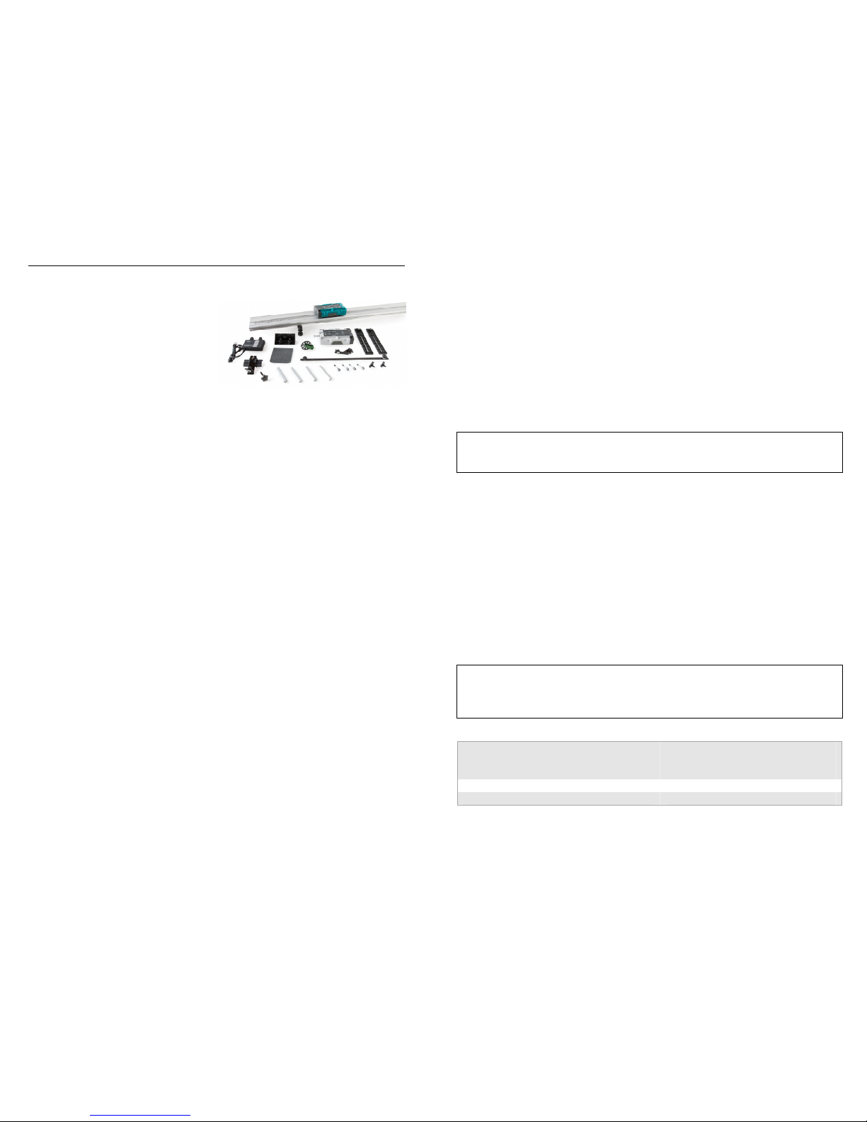
Calibration of the Motion Encoder System
Calibration of the Motion Encoder System is not necessary nor is it possible. The
printed bars on the track determine the scale, and the cart encoder counts the passage
of the bars. Available units are meters and feet, selectable in the software.
In contrast, it is possible and desirable to zero the encoder. Unlike an ultrasonic
motion detector, there is no way for the system to have an unchanging reference
position; it can only count bars from the point at which the cart is placed on the
track. As a result, you may want to move the cart to the receiver end of the track and
zero the reading in the software.
The positive direction can be reversed so that readings increase as the cart moves
toward the receiver. A reversed coordinate system is helpful when using two Motion
Encoder Systems to monitor the motion of two encoder carts, so that the positive
direction is the same in both cases.
Because the encoder strip must be continuous, the Motion Encoder System cannot be
used with a Track-to-Track Coupler.
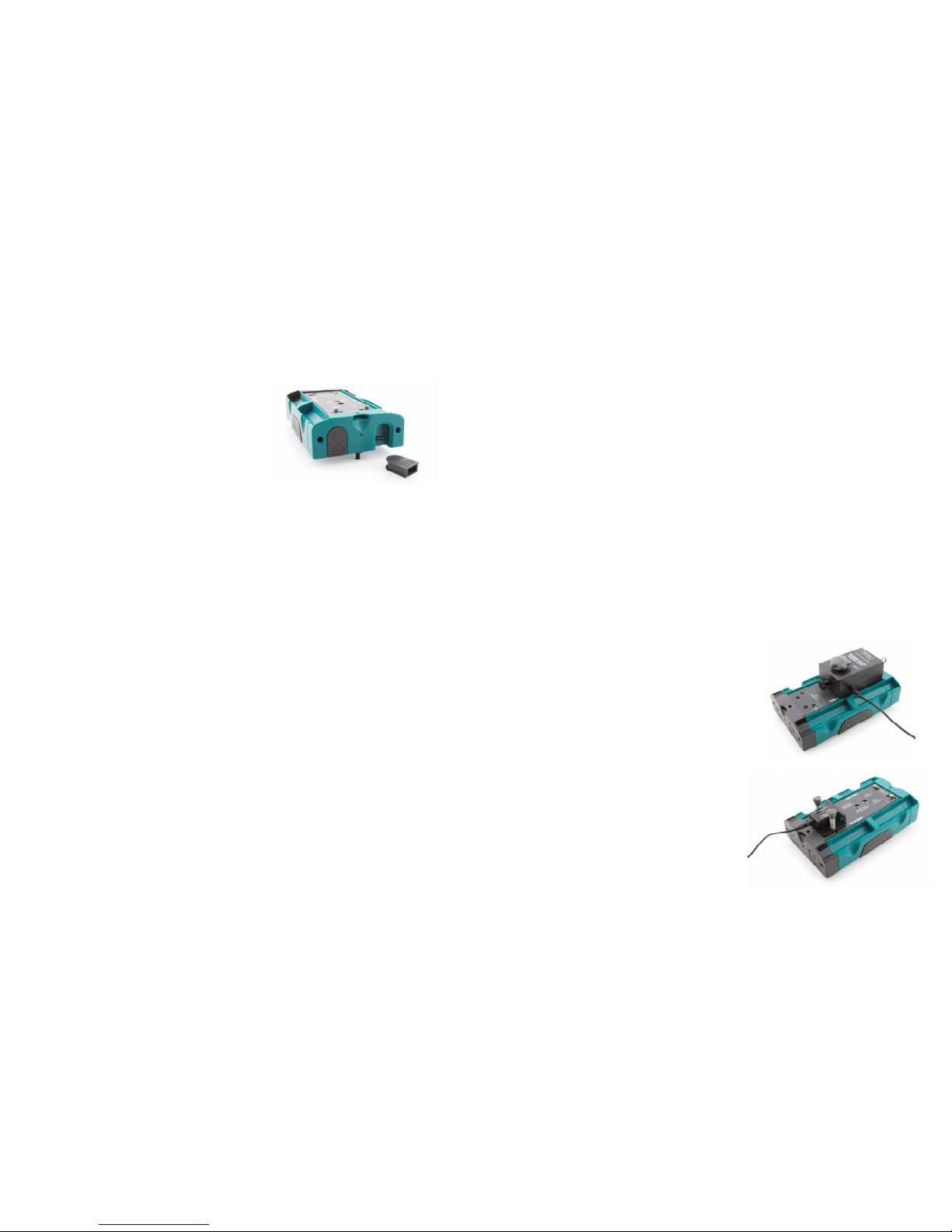
Power
The Motion Encoder Cart requires two AAA batteries. Either NiMH rechargeable
batteries or alkaline disposable batteries can be used. Turn on the cart by pressing the
clear power button on the cart endcap. It will glow blue when power is on. Press
again to turn off. The cart will turn itself off after 20 minutes of inactivity. Any
motion on the track will cause the timer to reset. The receiver is powered by the
data-collection interface.
Battery life depends on use and the range setting. Low battery level may cause
erratic detection of the cart motion, including incorrect velocity signs. Replace the
batteries if this is seen.
Range Setting of the Motion Encoder Cart
The IR transmitter on the cart has two power levels available. The default 1 m
setting conserves battery power. If the cart is used on a 2.2 m track, set the cart to the
higher 2 m power level. If the high-power setting is not used on a 2.2 m track, the
receiver will not reliably sense the position of the cart at the far end of the track. The
switch is located inside the battery compartment.
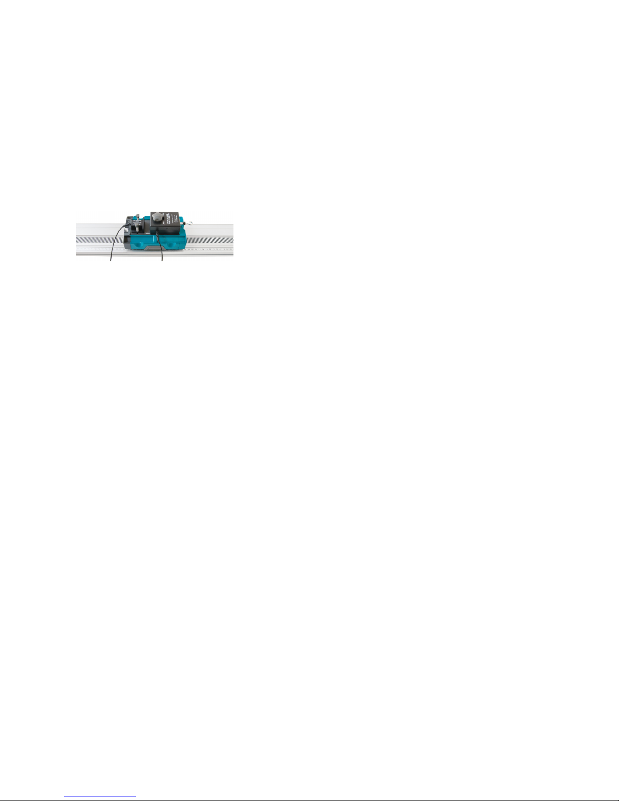
Use of Two Vernier Motion Encoder Systems on the Same Track
Some experiments require measuring the motion of two carts. This can be done by
purchasing the Motion Encoder Cart and Receiver (order code DTS-MEC) to add a
second encoder cart, receiver, and strip to your Vernier Motion Encoder System. A
Motion Encoder Receiver is placed at either end of the track, and two Motion
Encoder Carts are used on the track, each with its transmitter facing the unobstructed
receiver. A second encoder strip must be applied to the track, resulting in one on
either side of the center slot.
Consider reversing the direction of one receiver so that the same direction is positive
for each system. Put the carts together, and zero both systems. This will put the carts
4
on the same coordinate system; if they move together in contact, their position
readings will be the same.
Use of Multiple Vernier Motion Encoder Systems
in the Same Room
Because of the narrow IR beam used for signaling between the cart and receiver,
interference should be rare. However, if one apparatus is apparently interfering with
another, the problem can be resolved by repositioning one of the tracks.
All Motion Encoder Carts are interchangeable; that is, there is no matching of cart to
receiver.
Data-Collection Notes for the Motion Encoder System
The optical motion encoder can only make relative position measurements, so the
zero point is initially determined by the location on the track that the cart is first
placed when the power is on. If you want zero to be near the receiver, initially
place the cart next to the receiver. This behavior is very different from the
ultrasonic Motion Detector, which by default uses a fixed origin near the detector.
The motion encoder is nearly immune to interference, but it cannot work if the IR
beam between the cart and receiver is blocked. Keep your hand away from this
region.
Since the zero position (origin) of the encoder depends on where the cart is placed
initially, it is often useful to zero the encoder in the software. Place the cart in the
position that you want to declare as zero. On LabQuest, tap the Meter Screen to
access the zero command. In Logger Pro, use the toolbar button.
It can also be useful to reverse the direction of the coordinate system, so that
values increase as the cart moves toward the receiver. Do this from the Meter
Screen on LabQuest, or by using the Sensor menu in the Set Up Sensors dialog
box for your interface in Logger Pro.
High data-collection rates are not useful for the motion encoder. Rates above
30 Hz will produce noisy velocity and acceleration graphs because of few counts
during each time period.
Just like the ultrasonic Motion Detector, it can be useful to adjust the number of
points used to calculate derivatives for velocity and acceleration graphs. Higher
values create quieter graphs, while lower values result in more temporal detail.
Adjust this value in LabQuest preferences or in Settings For… from the File menu
in Logger Pro.
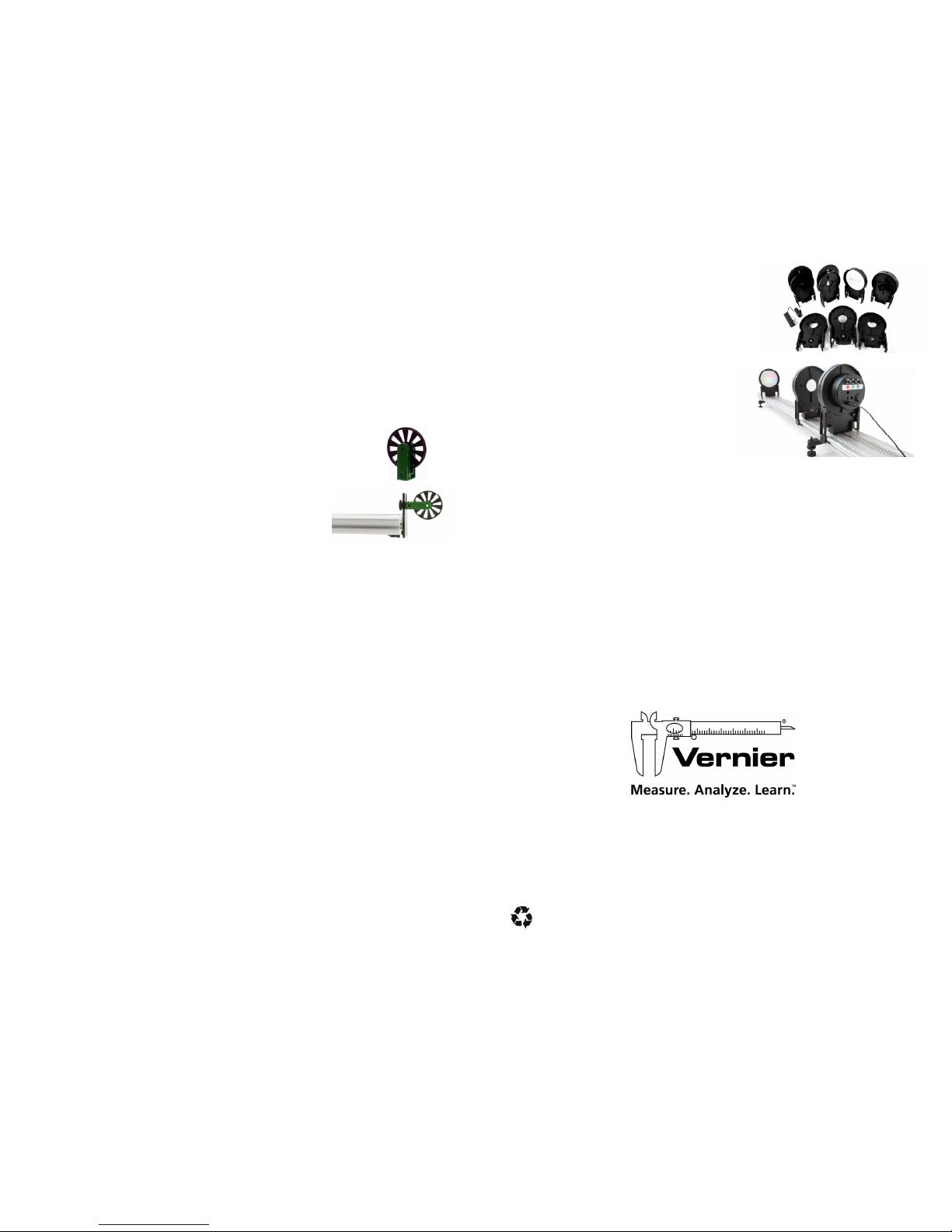
Photogate Bracket
Photogate Brackets are attached to the side of the track.
With the nut loosely on the T-handled bolt, slide the nut
into the side channel of the track. Attach the photogate
using the supplied wing bolt in the long slot. Adjust the
gate height so the beam intercepts the desired portion of
the target.