Verona VCLFSGG 365 D Series User manual

DOUBLEOVENDUALFUELRANGE
Models: VCLFSGE 365 D..
INSTALLATION INSTRUCTIONS
IMPORTANT - PLEASE READ AND FOLLOW
• Beforebeginning,pleasereadtheseinstructionscompletelyandcarefully.
• Donotremovepermanentlyaffixedlabels,warnings,orplatesfromtheproduct.Thismay
voidthewarranty.
• Pleaseobservealllocalandnationalcodesandordinances.
• Pleaseensurethatthisproductisproperlygrounded.
• The installer should leave these instructions with the consumer who should retain
for local inspector’s use and for future reference.
Installationmustconformwithlocalcodesorintheabsenceofcodes,theNationalFuelGas
CodeANSI Z223.1/NFPA 54 - Iatest edition. Electrical installation must be in accordance
with the National Electrical Code, ANSI/NFPA70 - latest edition and/or local codes. IN
CANADA: Installation must be in accordance with the current CAN/CGA-B149.1 National
GasInstallationCodeorCAN/CGA-B149.2,PropaneInstallationCodeand/orlocalcodes.
ElectricalinstallationmustbeinaccordancewiththecurrentCSAC22.1CanadianElectrical
CodesPart1and/orlocalcodes.
INSTALLATIONINMANUFACTURED(MOBILE)HOME:Theinstallationmustconformwith
theManufacturedHomeConstructionandSafetyStandard,Title24CFR,Part3280[formerly
theFederal Standardfor MobileHomeConstruction andSafety,Title24,HUD(Part280)]
or,whensuchstandardisnotapplicable,theStandardforManufacturedHomeInstallations,
ANSI/NCSBCSA225.1,orwithlocalcodeswhereapplicable.
INSTALLATIONINRECREATIONALPARKTRAILERS:Theinstallationmustconformwith
stateor othercodesor,inthe absenceofsuch codes,withthe StandardforRecreational
ParkTrailers,ANSIA119.5.
Installation of any gas-fired equipment should be made by a Iicensed plumber.A manual
shut-off valve must be installed in an accessible location in the gas line external to the
applianceforthepurposeofturningonorshuttingoffgastotheappliance(InMassachusetts
suchshutoffdevicesshouldbeapprovedbythe BoardofStateExaminersofPlumbers&
GasFitters).
Ifanexternalelectricalsourceisutilized,theappliance,wheninstalled,mustbeelectrically
groundedinaccordancewithlocalcodesor,intheabsenceoflocalcodes,withthenational
ElectricalCode,ANSI/NFPA70.
R
FOR INSTALLER ONLY
THIS RANGE IS FOR RESIDENTIAL USE ONLY
Some models are supplied with a protective lm on steel and aluminium
parts. This lm must be removed before installing/using the appliance.

2
WARNING !
To reduce the risk of tipping the appliance,
the appliance must be secured by properly
installed anti-tip device packed with the
appliance.
• ALL RANGES CAN TIP
• INJURY TO PERSONS COULD RESULT
• INSTALL ANTI-TIP DEVICE PACKED
WITH RANGE
• SEE INSTALLATION INSTRUCTIONS
–Do not store or use gasoline or other ammable vapors and
liquids in the vicinity of this or any other appliance.
–NEVER use this appliance as a space heater to heat or
warm the room. Doing so may result in carbon monoxide
poisoning and overheating of the appliance.
–WHAT TO DO IF YOU SMELL GAS:
• Do not try to light any appliance.
• Do not touch any electrical switch.
• Do not use any phone in your building.
• lmmediately call your gas supplier from a neighbor’s
phone. Follow the gas supplier’s instructions.
• lf you cannot reach your gas supplier, call the re
department.
–Installation and service must be performed by a qualied
installer, service agency, or the gas supplier.
If the information in this manual is not followed exactly,
a re or explosion may result causing property damage,
personal injury, or death.
WARNING !

3
This appliance is designed and manufactured solely for the cooking of domestic (household)
foodandinnotsuitableforanynonedomesticapplicationandthereforeshouldnotbeusedina
commercialenvironmement.
Theappliancewarrantywillbevoidiftheapplianceisusedwithinanonedomesticenvironmement
i.e.asemicommercial,commercialorcommunalenvironment.
CONVERSIONLABEL
DATAPLATE
TheGovernorofCaliforniaisrequiredtopublishalistofsubstancesknowntothestateofCalifornia
to cause cancer or reproductive harm and requires businesses to warn customers of potential
exposurestosuchsubstances.
WARNING!: Gasappliancescontainorproducesubstanceswhichcancausedeathorseriousillness
andwhichareknowntotheStateofCaliforniatocausecancer,birthdefectsorotherreproductive
harm.Toreducetheriskfromsubstancesinfuelorfromfuelcombustion,makesurethisappliance
isinstalled,operated,andmaintainedaccordingtothemanufacturer’sinstructions.

4
Screwdriver 2 - Wrench
T-handle
wrench
Tape
measurePencil
Adjustable
pliers
Adjustable
wrench
Suitable protective
gloves Drill
Hammer
INSTALLATION INSTRUCTIONS
WARNING!
THIS APPLIANCE MUST BE INSTALLED BY A QUALIFIED INSTALLER.
Installation must conform with local codes.
Improper installation, adjustment, alteration, services, or maintenance can cause injury or property damage. Consult a
qualied installer, service agente or the gas supplier.
TOOLS NEEDED FOR INSTALLATION (NOT SUPPLIED WITH THE APPLIANCE)
IMPORTANT: The use of suitable protective clothing/gloves is
recommended when handling, installing of this appliance.

5
GENERAL INFORMATION
1. Installationmustconformwithlocalcodesor,intheabsence
of local codes, with the National Fuel Gas Code, ANSI
Z223.1/NFPA54-LatestEdition,CAN/CGA-B149.1orCAN/
CGA-B149.2.
2. Installationinmanufactured(mobile)home:installationmust
conform with the Manufactured Home Construction and
Safety Standard, Title 24 CFR, Part 3280 [formerly the
Federal Standard for Mobile Home Construction and
Safety, Title 24, HUD (Part 280)] or, when such standard
is not applicable, the Standard for Manufactured Home
Installations, ANSI/NCSBCS A225.1, or with local codes
whereapplicable.
3. Installation in Recreational Park Trailers: installation must
conformwithstateorothercodesor,intheabsenceofsuch
codes, with the Standard for Recreational Park Trailers,
ANSI A119.5.
4. To eliminate risk of burns or re by reaching over heated
surfaceunits,cabinetstoragelocatedabovethesurfaceunits
shouldbeavoided.
5. Air curtain or other overhead range hoods, which operate
byblowinga downward air ow ontoarange, shall not be
used in conjunction with gas ranges other than when the
hoodandrangehavebeendesigned,testedandlistedbyan
independenttestlaboratoryforuseincombination.
6. WARNING!!
This appliance shall not be used for space heating. This
information is based on safety considerations.
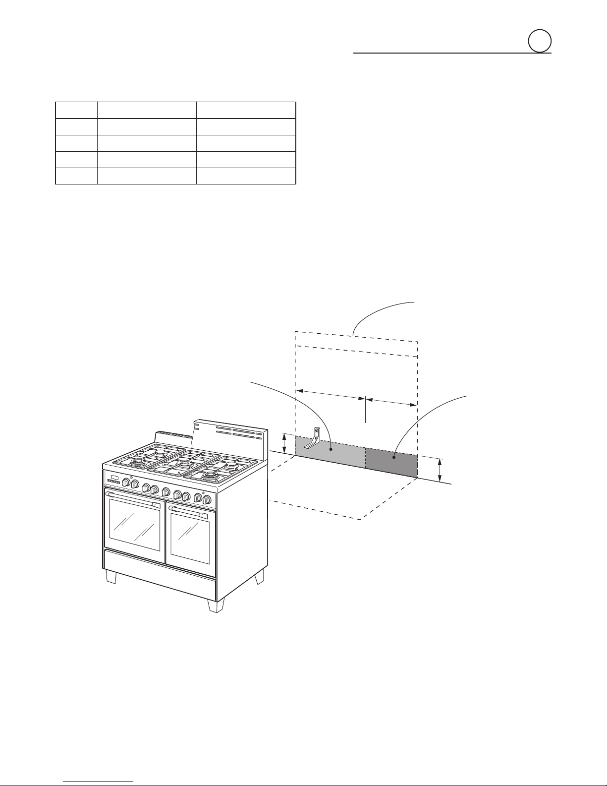
7. AlIopeningsinthewallbehindtheapplianceandintheoor
undertheapplianceshallbesealed.
8. Keep appliance area clear and free from combustible
materials,gasoline,andotherammablevapors.
9. Donotobstructtheowofcombustionandventilationair.
10. Disconnect the electrical supply to the appliance before
servicing.
11. Whenremovingapplianceforcleaningand/orservice;
A. Shutoffgasatmainsupply.
B. DisconnectACpowersupply.
C. Disconnectgaslinetotheinletpipe.
D. Carefullyremovetherangebypullingoutward.
CAUTION:Rangeisheavy;usecareinhandling.
12. Electrical Requirement
Electrical installation should comply with national and local
codes.
13. Air Supply and Ventilation
Theinstallermustreferstolocal/nationalcodes.
14. Gas Manifold Pressure
Naturalgas-4.0”W.C.P.
LP/Propane-11.0”W.C.P.
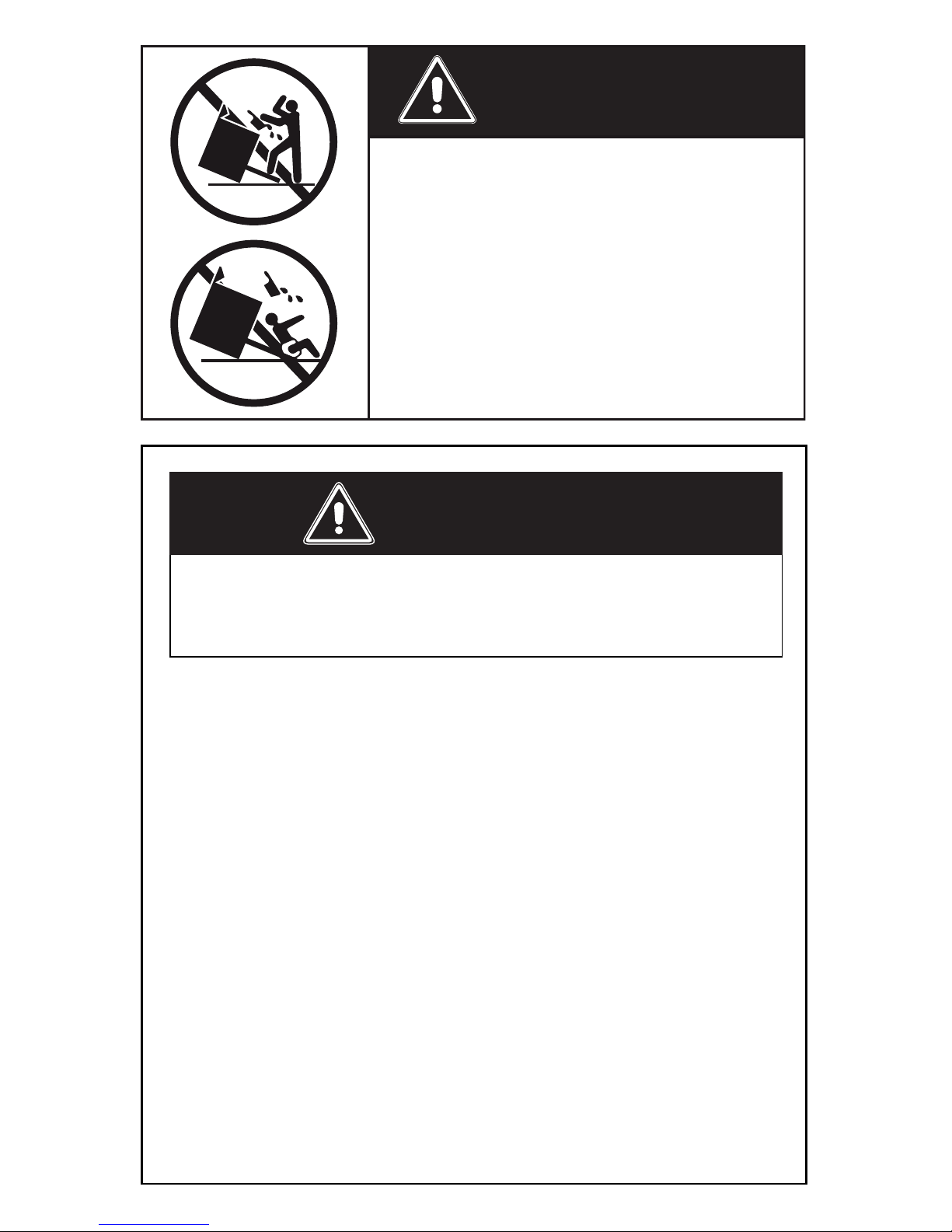
15. Themisuseofovendoor(e.g.stepping,sitting,orleaningon
them)canresultinpotentialhazardsand/orinjuries.
WARNING!!
ELECTRICAL GROUNDING INSTRUCTIONS
The range must be electrically grounded in accordance with
local codes or, in the absence of local codes, with the National
Electrical Code, ANSI/NFPA No. 70-latest edition, in Canada
Canadian Electrical Code.
Installation should be made by a Iicensed electrician.
FOR PERSONAL SAFETY, THIS APPLIANCE MUST BE
PROPERLY GROUNDED.
Ifanexternalelectricalsourceisutilized,theinstallationmustbe
electrically grounded in accordance with local codes or, in the
absenceoflocal codes, with the national Electrical Code,ANSI/
NFPA70.
REPLACEMENT PARTS
Only authorized replacement parts may be used in performing
serviceontherange.Replacementpartsareavailablefromfactory
authorizedpartsdistributors.Contactthenearestpartsdistributor
inyourarea.
16. Wheninstallingorremovingtherangeforservice,arollinglift
jackshouldbeused.Donotpushagainstanyoftheedgesof
therangeinanattempttoslideitintooroutoftheinstallation.
Pushingorpullingarange(ratherthanusingaliftjack)also
increases the possibility of bending the leg spindles or the
internalcouplingconnectors.

6
PROXIMITY TO SIDE CABINETS
1. Thisrangemaybeinstalleddirectlyadjacenttoexisting36"
(914mm)highbasecabinets.
Rangedimensions:
• width:35”7/8(911mm)
• depth:23”31/32(609mm)
• height (without backguard / island trim): MIN 35” 7/16
(900-mm)MAX35”5/8(905mm)
• backguard(height):8”(203mm)
• islandtrim(height):3”(76-mm)
Gaslineopening:
From5”1/8(130mm)to5”5/16(135mm)[dependingonfeet
regulation]fromthefloor;12”1/4(311mm)fromtheleftside
tocentreofrange.
Groundedoutlet:
Groundedoutletshouldbelocated23”5/8(600mm)fromthe
rightsidetocentreofrangeandfrom5”1/8(130mm)to5”
5/16(135mm)[dependingonfeetregulation]fromthefloor.
23" 31/32
(609 mm)
(911 mm)
35"
7/8
8"
(203 mm)
MIN 35" 7/16 (900 mm)
MAX 35" 5/8 (905 mm)
23"
31/32
(609 mm)
(911 mm)
35" 7/8
3"
(76 mm)
MIN 35" 7/16 (900 mm)
MAX 35" 5/8 (905 mm)
Fig.1.1a Fig.1.1b
2.TherangeCANNOTbeinstalleddirectlyadjacenttosidewalls,
tall cabinets, tall appliances, or other side vertical surfaces
above36”(914mm)high.
There must be a minimum of 11” 13/16 (300 mm) side
clearance from the range to such combustible surfaces TO
THELEFTorTOTHERIGHTabovethe36”(914mm)high
countertop.
IMPORTANT: One side (left or right) above the 36” (914
mm) high countertop must always be kept clear.
Installationwithislandtrim:Theremustbeaminimumof12”
(305mm)clearancefromthebackoftheislandtrimtosuch
combustiblesurfaceonthebackoftherangeabovethe36”
(914mm)highcountertop.
3.Themaximumuppercabinetdepthrecommendedis13”(330
mm).Wallcabinetabovetherangemustbeaminimumof30”
(762mm) above the countertop fora width ofminimum 35”
7/8(911mm):ithasto becentredwiththerange.Sidewall
cabinetsabovetherangemustbeaminimumof18”(457mm)
abovethecountertop.
Backguard
Islandtrim
installation
1

7
A
B
D
C
GAS AND ELECTRIC CONNECTION
Dottedlineshowingtheposition
oftherangewheninstalled
*:Dependingonfeetregulation
AreaforGASconnection AreaforELECTRICAL
connection
Fig.1.2
Rif. inch mm
A5”1/8÷5”5/16(*) 130÷135(*)
B23”5/8 600
C5”1/8÷5”5/16(*) 130÷135(*)
D12”1/4 311
1

8
(457 mm)
18" min.
30" min.
(762 mm)
(914 mm)
36"
0"
(0 mm)
0"
(0 mm)
20" min. (500 mm)
11"
13/16
min. (300 mm)
13" max. (330 mm)
(457 mm)
18" min.
30" min.
(762 mm)
(914 mm)
36"
0"
0"
(0 mm)
(0 mm)
20" min. (500 mm)
11"
13/16
min. (300 mm)
13" max. (330 mm)
OVEN VENT
OVEN VENT
Fig.1.3b
Fig.1.3a
PROXIMITY TO SIDE CABINETS
RANGE WITH BACKGUARD
1

9
(457 mm)
18" min.
30" min.
(762 mm)
(914 mm)
36"
0"
0"
(0 mm)
(0 mm)
20" min. (500 mm)
13" max. (330 mm)
11" 13/16 min. (300 mm)
12"
min. (305 mm)
(457 mm)
18" min.
30" min.
(762 mm)
(914 mm)
36"
0"
(0 mm)
0"
(0 mm)
20" min. (500 mm)
11"
13/16
min. (300 mm)
13" max. (330 mm)
12"
min. (305 mm)
OVEN VENT
OVEN VENT
OVEN VENT
Fig.1.3d
Fig.1.3c
PROXIMITY TO SIDE
CABINETS
RANGE WITH ISLAND TRIM
1

10
FITTING THE ADJUSTABLE FEET
Theadjustablefeetmustbefittedtothebaseofthecookerbeforeuse.
Resttherearofthecookeronapieceofthepolystyrenepackagingexposingthebase
forthefittingofthefeet.
ATTENTION: Most important! Pay special attention not to damage the range
during this operation.
Fitthe4legsbyscrewingthemtightintothesupportbaseasshowninpicture1.5.
LEVELLING THE COOKER
ThecookermaybelevelledbyscrewingthelowerendsofthefeetINorOUT(fig.1.6).
Itisimportanttoobservethedirectionsoffigure1.6.
Fig.1.7a Fig.1.7b Fig.1.7c
MOVING THE COOKER
WARNING
When raising cooker to upright position always ensure two people carry out this
manoeuvre to prevent damage to the adjustable feet (fig. 1.7a).
WARNING
Be careful: do not lift the cooker by the door handle when raising to the upright
position (fig. 1.7b).
WARNING
When moving cooker to its final position DO NOT DRAG (fig. 1.7c).
Lift feet clear of floor (fig. 1.7a).
1
Fig. 1.6
Fig. 1.5
Fig. 1.4

11
A
A
B
B
Fig.1.9
ASSEMBLING THE BACKGUARD
OR THE ISLAND TRIM
It is mandatory to install the backguard or the
island trim
• Assemble the backguard or the island trim
as shown in figure 1.8 or 1.9 and fix it
by screwing the 5 screws “A” (which are
alreadyfixedonthebackofthecooktop).
• Do not remove the 3 spacers “B” already
fittedonthebackofthebackguardorisland
trim.
1
IMPORTANT: THE BACKGUARD OR ISLAND TRIM IS NOT PACKAGED
WITH THE APPLIANCE BUT IT IS SUPPLIED SEPARATELY BY THE
DISTRIBUTOR.
WITH RESPECT TO THE FIGURES BELOW, ONE ADDITIONAL BACKGUARD
(HEIGHT = 4”) OR ISLAND TRIM (HEIGHT = 2”) IS ALSO AVAILABLE FOR
RANGE DEPTH = 25” ½.
IT IS MANDATORY TO INSTALL THE BACKGUARD OR
ISLAND TRIM.
A
B
A
B
Fig.1.8

12
ANTI-TIP STABILITY DEVICE INSTALLATION INSTRUCTIONS
1. Theanti-tipbrackethastobeattachedasshownonfigurebelow,ithastobefixedon
therearwallbyno.2(two)suitablescrews(suppliedwiththeanti-tipkit).
2. Afterfixingtheanti-tipbracket,sliderangeintoplace.Besuretheanti-tipbracketis
fullyinsertedintheslotoftherangeback.
YOU MUST USE STABILITY
ANTI TIP BRACKET TO
PREVENT UNIT FROM
TIPPING.
26" 31/32 (685 mm)
from top of cooktop
with range installed
in final position
(243.5 mm)
9" 37/64
Dottedlineshowingtheposition
oftherangewheninstalled
Slotforinserting
theanti-tipbracket
ANTI-TIPSTABILITY
DEVICEFIXING
Fig.1.10
Anti-tip
stabilitydevice
1

13
Gas supply line
Shutoff valve
“open” position
To range
Fig.2.1
All gas connections must be made according to national and local codes. This gas
supply (service) line must be the same size or greater than the inlet line of the
appliance.SealantonallpipejointsmustberesistanttoteactionofLP/Propanegas.
The range is equipped for the use with NATURAL gas. It is design-certified by CSA
International for NATURAL and L.P. gases with appropriate conversion.
The model/serial rating plate, located on the inner side of the storage compartment
pivotingpanel,hasinformationonthetypeofgasthatcanbeused.Ifthisinformation
doesnotagree with thetypeof gas available, checkwiththe local gas supplier.See
page from 19 to 21 for L.P. gas conversion inctructions.
1. Manual Shut-off Valve (fig.2.1):
A manual shut-off valve must be installed in an accessible location in the gas line
external to the appliance for the purpose of turning on or shutting off gas to the
appliance (In Massachusetts such shutoff devices should be approved by the Board
of State Examiners of Plumbers & Gas Fitters). This valve should be located in the
sameroomastherangeandshouldbeinalocationthatallowseaseofopeningand
closing(ina position where itcanbereachedquicklyintheeventof an emergency).
Do not block access to the shutoff valve. The valve is for turning on or shutting off
gas to the appliance.
2. Pressure Regulator:
a) Allheavyduty,commercialtypecookingequipmentmusthaveapressureregulator
ontheincomingservicelineforsafeandefficientoperation,sinceservicepressure
may fluctuate with local demand.
Beforeinstalling theregulator mount the 1/2” NPT(conical) male connector tothe
regulator(see picture2.2a).Gasketsupplied havetobeplacedbetween 1/2”NPT
(conical) connector/extension pipe male pipe fitting (see picture 2.2b).
Theregulatorsuppliedwiththisrangemustbeinstalledbeforeanygasconnections
are made.
Use supplied pressure regulator only.
b)Assemble the extension pipe + pressure regulator group to the range manifold
interposing the gasket supplied.
Explosion Hazard
Use a new CSA or UL approved
gas supply line.
Install a shut-off valve.
Securely tighten all gas
connections.
If connected to LP, have a
qualified person make sure gas
pressure does not exceed 14”
water column.
Examples of a qualified
person include licensed
heating personnel, authorized
gas company personnel, and
authorized service personnel.
Failure to do so can result in
death, explosion, or fire.
2
gas connection

14
PRESSURE REGULATOR INSTALLATION
1 2 3
A
STEP 2
Assemble the “A” bracket to the extension pipe.
Fig.2.2a
Fig.2.2b
STEP 1
Mountthe1/2”NPT(conical)maleconnectortothepressureregulatorandtighten
by using a wrench.
Do not over tighten the connector.
Over tightening may crack regulator.
2
Arrow
LOCK

15
STEP 3
Assemblethe1/2”NPTconnector+pressureregulatorgrouptotheextensionpipe
interposingthegasketsupplied.Theregulatorcovermustbeordientedtowardthe
front side of the range.
IMPORTANT: use two spanners to tighten the connection.
Regulator
cover
Fig.2.2c
B
B
STEP 4
Insert the extension pipe + pressure regulator
group in the “B” bracket.
Fig.2.2d
2

16
C
STEP 6
Fix the “C” bracket on the back of the range
by the 2 (two) screws supplied with the kit for
gas connection.
The regulator cover must be ordiented toward
the front side of the range.
Fig.2.2f
STEP 5
Assemble the extension pipe + pressure
regulatorgrouptotherangemanifoldinterposing
the gasket supplied. The regulator cover must
beordientedtowardthefrontsideoftherange.
IMPORTANT: use two spanners to tighten
the connection.
Fig.2.2e
2

17
Connector
Pressure
regulator
1/2” G cylindrical
(ISO 228-1) female
1/2” NPT
(conical)
male
1/2” NPT
female
1/2” NPT
female
1/2” G cylindrical
(ISO 228-1) male
Extension
pipe male
pipe fitting
Gasket
Range
manifold
Manifold male
pipe fitting
1/2” G cylindrical
(ISO 228-1) male
Extension
pipe female
pipe fitting
1/2” G cylindrical
(ISO 228-1) female
Gasket
Extension
pipe
Extension
pipe female
pipe fitting
Arrow
WARNING: check the right
positioning of the gas regulator.
The arrow on the gas regulator must
be oriented toward the connector.
To mains
connection
To range
PRESSURE REGULATOR INSTALLATION
Fig.2.3
2

18
Fig.2.4
TEST POINTADAPTER
TheTest Point adapteris available from
theAfter-SalesService.
c)Any conversion required must be performed by your dealer or a qualified licensed
plumber or gas service company. Please provide the service person with this
manualbeforeworkisstartedontherange.(Gasconversionsaretheresponsibility
of the dealer or end user.)
d) This range can be used with NATURAL or LP/PROPANE gas. It is shipped from
the factory adjusted for use with NATURAL gas.
e) Manifold pressure should be checked with a manometer and by operating as
below detailed:
- Remove the injector from the front left burner and mount the proper test point
adapter which is available from theAfter-Sales Service (see side figure and the
“OPERATIONSTOBEPERFORMEDWHENSUBSTITUTINGTHEINJECTORS”
chapter).
- Turn the front left burner control knob to the maximum position ( position)
- Press the knob and keeping it pressed check the manifold pressure with a
manometer;NATURALgasrequires4.0”W.C.P.andLP/PROPANErequires11.0”
W.C.P.
- Incoming line pressure upstream from the regulator must be 1” W.C.P. higher
than the manifold pressure in order to check the regulator.
- Theregulatorusedonthisrangecanwithstandamaximuminputpressureof1/2
PSI(14.0” W.C.P).If the linepressureis in excessofthat amount, astep-down
regulator will be required.
f) The appliance, its individual shut-off valve, and pressure regulator must be
disconnected from the gas supply piping system during any pressure testing of
that system at pressures in excess of 1/2 PSI (3.5 kPa).
g) The appliance must be isolated from the gas supply piping system by closing its
individualmanualshut-offvalveduringanypressuretestingofthegassupplypiping
system at test pressure equal to or less than 1/2 PSI (3.5 kPa).
3. Flexible Connections:
If local codes permit, CSA design-certified, flexible metal appliance connector is
recommendedforconnectingthisrangetothegassupplyline.DoNotkinkordamage
the flexible connector when moving the range. The pressure regulator has 1/2” NPT
femalepipethreads.Youwillneedtodeterminethefittingsrequired,dependingonthe
size of your gas supply line, flexible metal connector and shutoff valve.
4. Rigid Pipe Connections:
Ifrigidpipe is used as a gas supply line,acombinationofpipefittingsmustbeused
to obtain an in-line connection to the range. All strains must be removed from the
supply and fuel lines so range will be level and in line.
• Usejointcompoundsandgasketsthatareresistanttoactionofnaturalorpropane
gas on all male pipe threads.
• Donotovertightengasfittingwhenattachingtopressureregulator.Overtightening
may crack regulator.
5. Leak Testing:
IMPORTANT:Leak testing of the appliance shall be conducted as follows:
• After final gas connection is made, turn on manual gas valve and test all
connections in gas supply piping and appliance for gas leaks with a soapy water
solution. During this test all appliance gas valves have to be closed.
• In order to avoid property damage or serious personal injury, never use a Iighted
match. If a leak is present, tighten joint or unscrew, apply more joint compound,
tighten again and retest connection for leak.
2

19
1
2
NATURAL GAS
REGULATION
LP/PROPANE
REGULATION
A
component
Fig.2.5
REGULATOR
COVER
Pressure
regulator
CONVERSION TO LP/PROPANE GAS (OR CONVERSION
BACK TO THE ORIGINAL GAS - NATURAL GAS)
Every range is provided with a set of injectors for the various types of gas.
Select the injectors to be replaced according to the “INJECTORSTABLE”.
The nozzle diameters, expressed in hundredths of a millimetre, are marked on the
body of each injector.
CAUTION: Save the orifices removed from the appliance for future use.
SETTING THE PRESSURE REGULATOR(fig.2.5)
The pressure regulator is accessible through the storage compartment by opening
the bottom pivoting panel; the pressure regulator is positioned on the rear left side
of the range.
To set the pressure regulator:
1.Unscrewtheregulatorcover;
2.Unscrewthe"A"component,reverseandscrewitaccordingtotheLP/PROPANE(or
NATURALGAS)regulation.
2

20
OPERATIONS TO BE
PERFORMED WHEN
SUBSTITUTING THE
INJECTORS
• Removethegratingsandtheburner
covers;
• Usingawrenchsubstitutethenozzle
injectors“J”(figs.2.6a-2.6b-2.6c)
withthosemostsuitableforthekind
ofgasforwhichitistobeused.
The burner are conceived in such a
way so as not to require the regulation
of the primary air.
Fig.2.6a Fig.2.6b
Fig.2.6c
INJECTORS TABLE
Semi-rapid
burner
Triplering
burner
DUAL
burner
BURNERS
NOMINAL POWER
BTU/hr
REDUCED POWER
BTU/hr
LP/PROPANE
11”W.C.P.
NATURAL GAS
4”W.C.P.
Øinjector
[1/100mm]
Øinjector
[1/100mm]
Semi-rapid (R) 6000 1500 72 118
Triple ring (TC) 12000 5000 102 170
Dual (D)
Inner crown
2800 forNATURALGAS(*)
3500 forLP/PROPANEGAS(*)
1000(*) 55
(no.1central)
80
(no.1central)
Outer crowns
16000 forNATURALGAS(#)
15000 forLP/PROPANEGAS(#)
6500 forNATURALGAS(#)
4500 forLP/PROPANEGAS(#)
72
(no.2outer)
130
(no.2outer)
J
Injectorforinnercrown
J
Injectorsfor
outercrowns
J
J
(*)Powercalculatedonlywithinnercrownoperating
(#)Powercalculatedwithinnerandoutercrownsoperating
2
Other manuals for VCLFSGG 365 D Series
4
Table of contents
Other Verona Oven manuals

Verona
Verona VEBIEM241SS User manual

Verona
Verona VEBIEM301SS User manual

Verona
Verona VEBIG30N Series User manual

Verona
Verona VEBIE3024SS User manual

Verona
Verona VEBIG30N Series Operation instructions

Verona
Verona VEBIG30SS Manual

Verona
Verona VCLFSGG 365 D Series Operation instructions

Verona
Verona VEBIEM241SS User manual

Verona
Verona VEBIEM3030DSS User manual

Verona
Verona VPFSGE365D Series User manual