11 LIMITED WARRANTY
Vertex Water Products (“ anufacturer”) sell its products through independent retailer dealers (“Dealer”) who re-sell
to the end-user customer. In this limited warranty, “Vertex” refers to Vertex Water Products and not to the Dealer.
WHO IS COVERED BY THIS WARRANTY
This limited warranty covers only the first purchaser of the Vertex PureWaterCooler™ from a Dealer for use by that
purchaser, and is not transferrable. “Consumer Use” means personal residential household use by a consumer or
consumers. “Commercial Use” means all other uses, including (but not limited to) use for commercial, income pro-
ducing purposes and/or when purchased by a business and/or when purchased for use in an office, business, or indus-
trial setting. “Purchaser” means the end-user customer, and not a Vertex re-seller Dealer.
PERIOD OF COVERAGE OF THIS WARRANTY
anufacturer warrants the complete water cooler (“the unit”) against defects in material and workmanship, subject to
the exclusions described below, for a period of ONE YEAR, beginning on the later of either (a) the date of purchase
or (b) the date of manufacture as identified by the Vertex unit’s serial number. anufacturer additionally warrants
the compressor for a period of THREE YEARS from the above date. The purchaser must provide the original sales
receipt as proof of the date of purchase. If the purchaser is unable to produce the original sales receipt, the Warranty
Period commencement date will be determined by anufacturer, in its sole and absolute discretion, based upon the
unit’s serial number. This warranty does not apply if the original serial number affixed by anufacturer is removed,
defaced, altered, obscured, tampered with, or obliterated. If anufacturer provides a replacement part or parts, or
repairs a part or parts, under this limited warranty, then the replacement part(s) or repaired part(s) will be covered
under this limited warranty for the time remaining under the original Warranty Period applicable to the part(s) re-
paired or replaced.
The duration of ALL OTHER WARRANTIES, INCLUDING ANY AND ALL IMPLIED WARRANTIES,
INCLUDING BUT NOT LIMITED TO MERCHANTABILITY AND FITNESS FOR A PARTICULAR PUR-
POSE, ARE RESTRICTED TO THE TWO-YEAR LIMITED WARRANTY PERIOD. Some states do not
allow limitations on how long an implied warranty lasts, so the above limitation may not apply to purchaser.
WHAT IS COVERED BY THIS WARRANTY
This limited warranty covers defects in materials or workmanship, subject to the exclusions below and for the time
period stated above. anufacturer promises to repair or to replace, at anufacturer’s sole and absolute discretion,
any part of this water cooler that proves to be inoperative due to a defect in material or workmanship under normal
use.
WHAT IS NOT COVERED BY THIS WARRANTY
This limited warranty does not extend to and expressly excludes:
• conditions, losses, malfunctions, or damages not resulting from defects in material or workmanship;
• conditions, malfunctions, losses, or damages or the inability to operate the Vertex unit resulting from
conditions beyond anufacturer’s control, including but not limited to failure of the unit or any of its
parts due to damage caused by: improper installation; accident; fire; flood; windstorm; acts of God;
rodent and/or insect infestation; vandalism; modification; alteration; combination with any other device
or machine; abuse and/or misuse of the unit; negligence by purchaser or third parties; any part of the
water system that has become fouled due to liming, dirt, unsatisfactory/unsanitary water conditions,
corrosion, or faulty plumbing; failure to install, maintain, assemble, mount or place the Vertex unit in
accordance with anufacturer’s instructions and/or local, state, or national plumbing and electrical
codes; wear and tear expected to occur in the normal course of use, including but not limited to cosmetic
rust, scratches, dents or comparable and reasonably expected losses or damages; exposure to extreme
variations in ambient environmental conditions (including but not limited to changes in heat, humidity,
moisture, or exposure to sunlight).
• labor for installation or deinstallation of the unit or any of its parts; shipping of the unit or any of its parts
to anufacturer for repair/replacement.
In addition to the above exclusions, this limited warranty does not apply if any of the following conditions
of operation are not met: System Pressure 35 - 100 psi, Temperature 40 - 100 degrees F, PH range 4 - 10, ax TDS
1500 PP ax., Turbidity <1.0NTU, Hardness <20gpg, R version: <3.5 gpg, F version, Iron
<0.1 mg/l, anganese <0.1 mg/l, Hydrogen Sulfid e <0.00 mg/l.
17
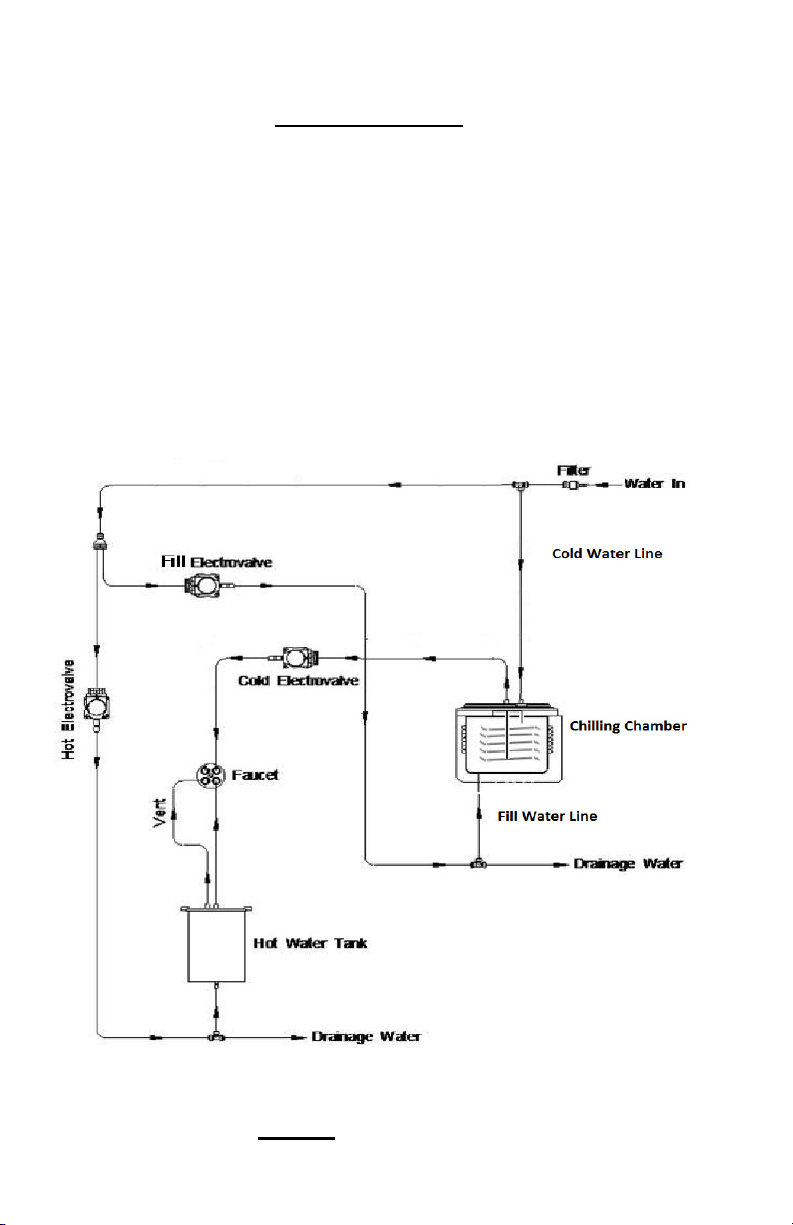
.1 Assembly
The countertop portion of the PWC-9500 assembly drawing is shown in
Figure 1. The cooler has one chilling chamber and one hot tank. This chilling
chamber holds one gallon of water and is automatically filled at start-up. This
water is cooled in the chilling chamber with refrigerant coils. The cold water
drinking line is comprised of a sealed stainless steel coil submerged inside this
chamber. There is a separate hot water tank with an internal heater coil which is
fed by water pressure directly from the line in. The hot water tank is directly be-
side the cold water tank. The compressor and expansion valve are inside the
cabinet. The controls for dispensing water are on the front panel.
.0 Description
2
Figure 1 Flow Schematic