8
MONTAŻ RĘKOJEŚCI POMOCNICZEJ
Rękojeść pomocniczazostałazaprojektowanazarówno dlaosób
prawo jak i leworęcznych. Rozpoczynającpracę zawsze należy
trzymać podkaszarkę pewnie, obiemarękami z wykorzystaniem obu
rękojeści.
•Odkręcić nakrętkę blokady rękojeści pomocniczej (13) i wyjąć
śrubę z rękojeści pomocniczej (12).
•Nasunąć obejmę rękojeści pomocniczej (12) tak, aby jej
mocowanie trafiło w gniazdaw obudowie rękojeści zasadniczej.
•Wsunąć zdemontowaną śrubę w otwór i dokręcić nakrętkę
blokady rękojeści pomocniczej (13) (rys. B).
REGULACJA RĘKOJEŚCI POMOCNICZEJ
•Poluzować nakrętkę blokady rękojeści pomocniczej (13) ustawić
rękojeść pomocniczą (12) w najbardziej dogodnym położeniu dla
wykonywanej pracy.
•Dokręcić nakrętkę blokady rękojeści pomocniczej (13) arękojeść
pomocnicza(12) zostanie zablokowanaw wybranym położeniu
(rys. B).
REGULACJA DŁUGOŚCI RURY TELESKOPOWEJ
Regulacjadługości rury teleskopowej pozwalanadopasowanie
wysokości urządzeniadlaosóbo różnym wzroście i postawie. Zakres
regulacji 90 cm ÷ 120 cm.
•Poluzować pierścień blokady rury teleskopowej (6) zgodnie z
oznaczonym kierunkiem obrotu.
•Wysunąć / wsunąć rurę teleskopową (7) napożądaną długość (rys.
C).
•Zablokować dokręcającpierścień blokady rury teleskopowej (6).
USTAWIENIE KÓŁ JEZDNYCH / WYSOKOŚCI KOSZENIA
W zależności od wysokości koszeniakołajezdne (8) podkaszarki
mogą być ustawione w pięciu różnych położeniach (oznaczone na
osłonie). Poszczególne położeniaodpowiadają wysokości koszenia
35, 47, 60, 68 i 75mm.
•Wybrać odpowiednią wysokość koszeniai odciągająckoło jezdne
(8), przekręcić w odpowiednie położenie.
•Zwolnić nacisk nakoło jezdne (8) (wspornik kołajezdnego (8)
powinien zazębić się z nacięciami w obudowie (rys. D).
Wysokość koszenia należy ustawiać tak samo dla wszystkich kół
jezdnych.
OBROTOWA RĘKOJEŚĆ ZASADNICZA
Dzięki funkcji obracaniarękojeści zasadniczej (1) względem głowicy
(11) istnieje możliwość pionowego przycinaniakrawędzi trawników
i klombów.
•Wcisnąć przycisk blokady rękojeści zasadniczej (14) i obrócić
rękojeść zasadniczą (1) o 1800do słyszalnego zatrzaśnięcia
przycisku blokady rękojeści zasadniczej (14) (rys. E).
MONTAŻ KOŁA DO KRAWĘDZI
Koło do krawędzi przeznaczone jest do pionowego przycinania
trawy nakrawędziach lubw narożach trawników.
•Zdemontować zaślepkę (10) z obudowy głowicy (11) wysuwając
jado góry (rys. F).
•Zamontować koło do krawędzi (16) wsuwającgo w prowadnice w
obudowie głowicy (11) (rys. G).
Demontaż kołado krawędzi przebiegaw odwrotnej kolejności do
jego montażu.
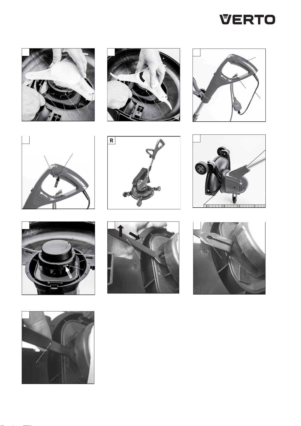
MONTAŻ SZPULI Z ŻYŁKĄ TNĄCĄ
Przed zamontowaniem szpuli z żyłką tnącą należy zamontować
suwak i sprężynę w dolnej części obudowy szpuli.
•Umieścić sprężynę (17) i suwak (18) w prowadzeniu obudowy
szpuli (19) jak przedstawiono narys. H
•Suwak (18) powinien dać się swobodnie przesunąć w prowadzeniu
i powinien powrócić do położeniapierwotnego.
•Odwinąć (po około 15cm) i przewleckońce żyłki tnącej (20) przez
otwory (b) w pokrywie szpuli (21).
•Wsunąć szpulę z żyłką tnącą (22) w pokrywę szpuli (21) (rys. I).
•Umieścić pokrywę szpuli (21) wraz ze szpulą z żyłką tnącą (22) w
obudowie szpuli (19) (rys. J) i zabezpieczyć pokręcającw prawo
(kierunek zamykaniai otwieraniapokazany napokrywie szpuli).
Demontaż szpuli z żyłką tnącą przebiegaw odwrotnej kolejności do
jej montażu.
MONTAŻ OSŁONY PRZEDNIEJ
Zamontowanie osłony przedniej pozwalanawykorzystanie
urządzeniado pracy jako kosiarka.
•Połączyć osłonę przednią (23) z osłoną tylną (9) wsuwającjej
zatrzaski w prowadzeniaosłony tylnej (9).
•Zabezpieczyć przekręcajączaczepy osłony (24) (po obu stronach)
i zapiąć klamrę (25) (rys. K).
Demontaż osłony przedniej przebiegaw odwrotnej kolejności do jej
montażu.
MONTAŻ WORKA NA TRAWĘ
•Unieść pokrywę wylotu (26) i wsunąć prowadzenie workanatrawę
(27) w prowadnice w osłonie przedniej (23) (rys. L).
•Zwolnić nacisk napokrywę wylotu (26)
Worek natrawę utrzymywany jest we właściwym położeniu za
pomocą siły sprężyny pokrywy wylotu. Demontaż workanatrawę
celem jego opróżnieniaprzebiegaw odwrotnej kolejności do jego
montażu.
MONTAŻ NOŻA TRÓJZĘBNEGO
Nie wolno pracować urządzeniem z zamontowanym nożem
trójzębnym bez założonych obu osłon.
•Montaż nożatrójzębnego jest łatwiejszy przy zdemontowanej
osłonie przedniej (23).
•Jeśli zamontowanaodkręcić pokrywę szpuli (21) i wyjąć wraz ze
szpulą z żyłką tnącą (22) (postępować w odwrotnej kolejności do
jej montażu).
•Wsunąć klucz specjalny (c) w łopatki wentylatoraznajdujące się
pod obudową szpuli (19) celem zablokowaniawrzeciona.
•Wycięcie w kluczu specjalnym (c) należy wsunąć najedną z łopatek
wentylatorai unieść konieckluczaspecjalnego (c) lekko do góry
(zagiętakońcówkakluczapowinnabyćskierowanadodołu) (rys.U).
UWAGA: Nieprawidłowe osadzenie kluczaspecjalnego (c) może
być powodem wyłamaniałopatki/łopatek wentylatora(rys. W).
Prawidłowe osadzenie kluczaprzedstawiono narys. X
•Blokująckluczem specjalnym (c) wrzeciono włożyć mocowanie
nożatrójzębnego (28) w gniazdo obudowy szpuli (19) (rys. M) i
obrócić w prawo celem jego zamocowania(rys. N).
•Sprawdzić poprawność zamocowania. Usunąć klucz specjalny (c).
•Zamontować osłonę przednią (23).
Demontaż nożatrójzębnego przebiegaw odwrotnej kolejności do
jego montażu.
ZABEZPIECZENIE PRZEWODU PRZEDŁUŻACZA
Do urządzenia wolno stosować wyłącznie przedłużacze
przewidziane do użytku na zewnątrz. Przekrój żył przedłużacza
powinien wynosić, co najmniej 1,5 mm2, którego maksymalna
długość nie powinna przekraczać 60 m.
W celu umożliwieniabezpiecznego koszenianależy przewód
przedłużaczaprzeprowadzić przez uchwyt przewodu (5) (rys. O) w
rękojeści zasadniczej zapewniający wyeliminowanie zbytecznego
naciągu przewodu przedłużaczapodczas pracy.
PRACA / USTAWIENIA
WŁĄCZANIE WYŁĄCZANIE
Napięcie sieci zasilającej musi odpowiadać wielkości napięcia
podanego na tabliczce znamionowej podkaszarki.
Włącznik podkaszarki posiada zabezpieczenie przed
przypadkowym uruchomieniem.