OVERUM CT User manual

Instruction manualInstruction manual
Conventional ploughsConventional ploughs CTCT


This instruction manual deals with Överum conventional ploughs type CT
_______________________________________________________________
Contents Page
1Description of function 2
1.1 Identification of plough 3
2General safety precautions with safety signs 4
3Technical description 5
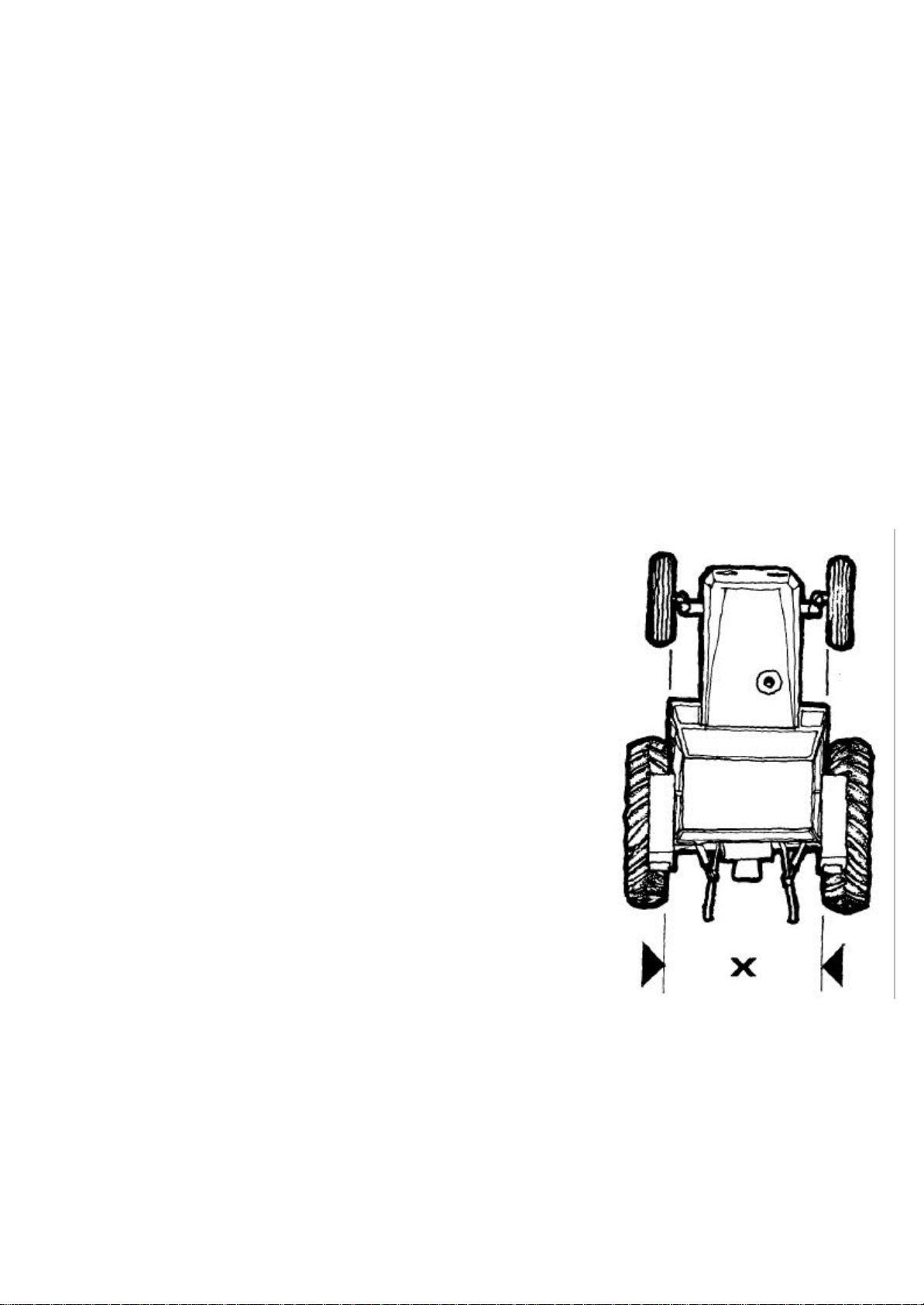
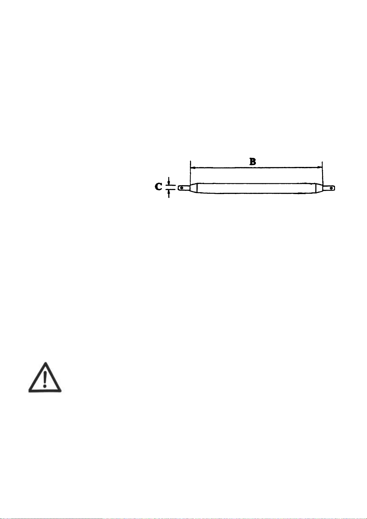
3.1 Checking the tractor prior to ploughing 5
3.2 Preparation of plough 6
3.3 Mounting the plough onto the tractor 6
3.4 Checking the plough 7
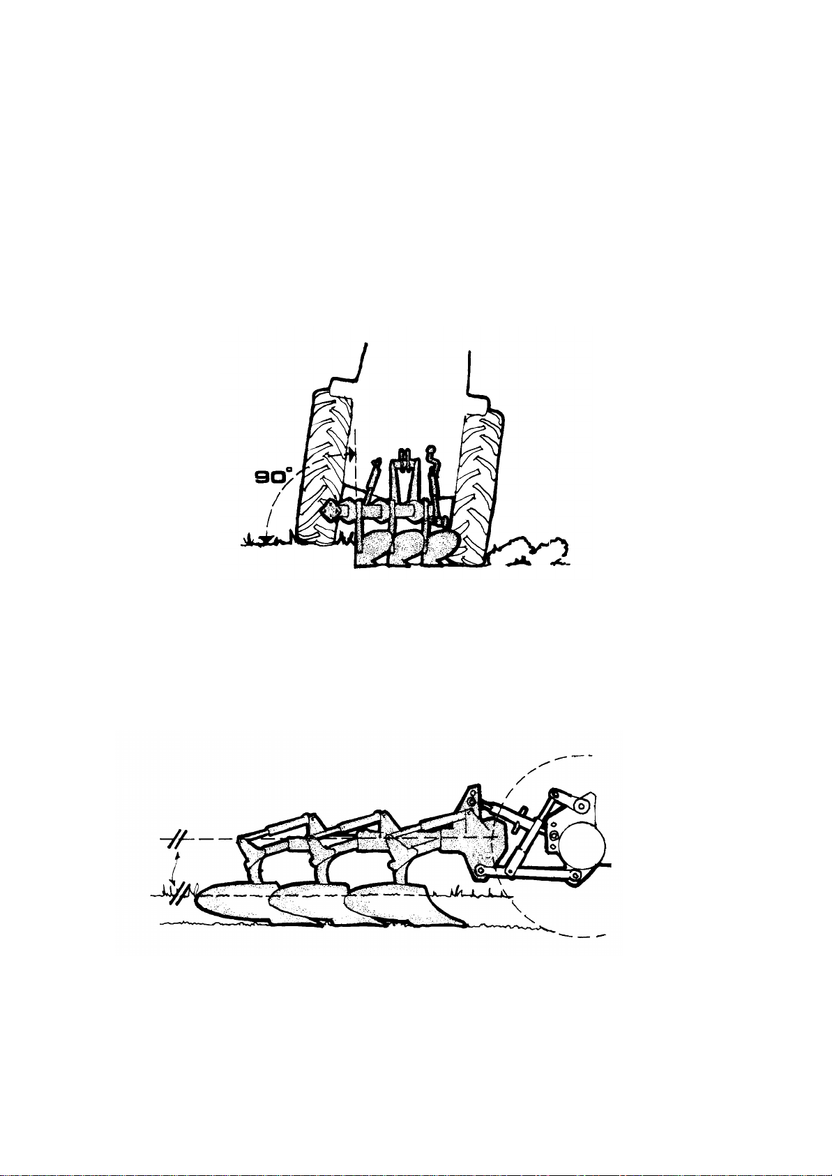
4Basic settings8
4.1 Basic settings mounted ploughs 8-9
4.2 Adjustment of skimming device 10-11
5Stone trip system 12
5.1 Shear bolt protection (F) 12
5.2 Hydraulic type (H) 12
5.3 Adjustment of operating pressure 13
5.4 Checking the accumulator 13
6Adjustment of working width 14
6.1 Adjustment of working width 14-15
7Care, maintenance and replacement of wearing parts 16
7.1 Greasing of the beam hinge points 16
7.2 Winter storage 16
7.3 Replacement of wearing parts 17
7.4 Mouldboards, Tightening torques 18
7.5 Lubrication chart 19
8Extra equipment 20
9Useful advice 21
Read these instructions carefully. If you follow the instructions given, YOU can expect good results
along with a good economic return from YOUR choice of plough.
If carefully operated, adjusted and maintained, the plough will meet all reasonable demands made on it
and will give YOU reliable service in years to come. Should YOU need further instructions, which
are not included in this manual, or require the help of experienced service personnel, we advise YOU
to contact one of our local representatives, which also will have spare parts in stock.
It has always been the ambition of Överums Bruk to constantly improve its products. Consequently,
in the interest of product improvement, no specification is final or binding and we reserve the right to
alter the design of new machine series and equipment without previous notice.
Överums Bruk AB
SE-590 96 Överum
Telephone: Int+46 493 361 00

1. DESCRIPTION OF FUNCTION
The plough is designed only for ploughing of all types of soil, and for transport between the farm and the
different fields.
The plough is to be attached to the three-point linkage at the rear of the tractor, with the hydraulic systems
connected to the appropriate hydraulic outlets.
Description of the plough
CT 4980 Mould board shin Mouldboard Share Point
Stone trip
cylinder
Cross-shaft
Disc coulter
Accumulator

Överums Bruk AB S-590 96 Överum Sweden
1.1 Plough identification
Type designations
Mounted conventional plough CT 2975 – 51080
Stone trip device H= hydraulic
F= fixed (shear bolt)
Beam height 75 = 75 cm
80 = 80 cm
Plough body spacing 9 = 90cm
Number of plough body pairs
Type
CT 4975 H
03 276893
Serial number
Complete the sign below with the TYPE DESIGNATION and the SERIAL NUMBER of Your plough.
Överums Bruk AB S-590 96 Överum Sweden

2. GENERAL SAFETY PRECAUTIONS WITH
SAFETY SIGNS
Safety signs
Carefully follow the Operating Instructions and Safety Signs, which warns for risks
when personal injuries can occur. Avoid accidents by always following the safety
precautions.
Read "Operator's Manual". Safety signs with no text are
used on these ploughs. Replace any missing safety decals
or any that have become illegible.
§Ensure that no person is on, underneath or in the
hazardious area of the plough during transport, or
ploughing.
§Never work with components in the hydraulic stone
release system unless the pressure is omitted.
§Be alert, there is always a risk for injuries when adjusting disc coulters and
skimmers.
§Operator competence. The operator must be well acquainted with the different functions of the
plough and be knowledgeable of how to operate it with safety. Consult the tractor manufacturers
manual on mounting implements and safe working methods.
§Ensure that the plough is locked with the correct locking pins onto the three-point linkage on the
tractor.
§Secure the lower link stabilizers on the tractor when the plough is transported on the road.
§The brake pedals on the tractor must be locked together when driving on the road.
§All hydraulic connections between tractor and plough must be made in accordance with the
instructions given.
§Never park the tractor with the plough in an uplifted position.
§Always use the support leg when parking the plough.
§Never attempt to clean or adjust the plough during operation.
§Never touch the gas valve on the accumulator.
§Wear suitable gloves when replacing wearing parts which can have sharp edges.
§The plough must always be attached to the three-point linkage on the tractor when altering the
working pressure in the hydraulic stone release system.
§Adapt the ploughing speed to suit the ground conditions. DRIVE CAREFULLY.
§Maximum transport speed 25 km/h.
§These rules however do not exempt the operator from the responsibility to observe relevant
statutory or other national regulations dealing with road safety or labour safety issues.

3. TECHNICAL DESCRIPTION
3.1 Checking the tractor prior to ploughing
Function of the three-point hitch
The design of the three-point linkage is based on the principle that the tractor and the plough should
operate as one unit. This function is depending of the settings for the lower links and the top link. These
components must therefore be maintained in a condition that enables them to be easily adjusted.
Hydraulics
Following external hydraulic outlets are required:
CT 1 double-acting
If the plough is equipped with hydraulic front furrow adjustment cylinder one extra double acting
hydraulic outlet is required.
Familarize yourself with the hydraulic systems of the tractor.
Wheel adjustment - Track width
For ploughing purposes, track width is always measured between
the inside walls on the tractor tyres.
The measurement between the inner walls of the front wheels must
be at least equal to the inner measurement between the rear wheels,
but may be up to 10 cm wider.
The distance between wheels must be symmetrical, relative to the
centre line of the tractor.
The following track widths are recommended: 1200 - 1500 mm
Ideal track width = 3 x the furrow width + 100-150 mm
(Example: 16" furrow width 3 x 400 + 125 = 1325 mm)
When ploughing with "wide tyres" the outside walls of the front
and the rear tyres should be parallel.
The furrow widener knives should be mounted on the last plough
body.
Tire pressures
Both tyre life and optimum traction are achieved by using the correct tyre pressure. Over-inflation
will increase wheel slip. Make sure that both rear tyres are inflated to the same pressure.
Front ballast weights
The front of the tractor should be fitted with balance weights as required to maintain optimal traction and
directional stability.

3.2 Preparation of the plough
Check that the quick-couplings on the hydraulic hoses are the same type as the quick-couplings on the
tractor. If required, fit the correct quick-couplings, to suit your tractor.
Check that the cross-shaft on the plough has the correct category to suit your tractor.
Cross shafts are available in different categories:
Cat. 2 means ø 28 mm cross-shaft pins
Cat. 3 means ø 36 mm cross-shaft pins
The length of the cross shaft is determined by the track widths of the tractor and the spacing of the lower
links on the tractor's rear axle. When the spacing is > 550 mm on the tractor's rear axle, use the 965 mm
long cross shaft.
Cat BC
2825 ø 28
2L 965 ø 28
3965 ø 36
3.3 Mounting the plough on to the tractor
Make sure that the lower links can be lowered approximately 20 cm below the cross shaft of the plough
before the plough is mounted onto the tractor.
Check that the link ball joints are of the same category as the cross shaft pins. Lock the cross-shaft into
the tractor’s lower links with sufficient locking pins.
The stabilizers for the lower links should be adjusted so that the plough can move freely in working
position but when raised the side movements should be limited.
The top link should be mounted slightly higher on the plough than on the tractor.
Consult the tractor manufacturers manual on mounting implements
and safe working methods.

3.4 Checking the plough
•Check the tightness of all bolts and nuts
•Grease all lubrication points
•Check the tyre pressure 23 x 8,5-12 240 kPa (2,4 bar)
•Check that the desired furrow width is correctly, set see page 14.
•MOULDBOARDS
For best results, the protective paint on new mouldboards should be removed before using the plough
for the first time. Use of a paint stripper is the easiest way of removing the paint. The paint can also
be removed by using a scraper or a similar tool. Under no circumstances should the paint be burned
off, since the necessary heat would ruin the temper of the steel. This also applies to any disc coulters
and skim coulters used.
•Check the disc coulter and skim coulter settings and adjust them so that the settings are identical.
•Raise the plough and fold up the support leg.
•Always remember to re-tighten all nuts and bolts after about 3 hours of use, after that
check the tightening of the bolts regulary.
Stone trip device (H-system)
Check the working pressure by reading the pressure gauge. For suitable working pressure, see page 13.

4. BASIC SETTINGS
4.1 Basic settings, mounted ploughs
The basic setting can be started when the desired ploughing depth has been reached and when the tractor
wheels are running in a furrow with the same depth.
1. Vertical adjustment
Ensure that the plough beams are at right-angle 90º to the ground. If necessary, make adjustments by
using the right-hand lower link of the tractor. The angle is best seen when standing behind the plough.
2. Horizontal and depth adjustments
Mount the top link so that it is 5-10 cm higher on the plough than on the tractor when in working position.
The top link bracket of the plough is adjustable laterally in two positions.
Ensure that the front and rear plough bodies are ploughing at the same depth, the plough frame should be
parallel with the ground. Adjust by altering the length of the top link.
The ploughing depth should be controlled by means of the tractors draught control in combination with
the depth wheel of the plough. This provides a good weight transfer in hard parts of the fields and a good
control of the working depth in lighter soils.

3. First furrow width
Ensure that the lower links are loose so the plough can move freely.
For ploughs equipped with a hydraulic control of the first furrow width, the following applies: Place
the hydraulic cylinder in a central position so that it can be adjusted in both directions. Check that the
cross-shaft has the correct angle adjustment, see page 14 (Furrow with adjustment ). The adjustment is
made with the turnbuckle.
If the width of the first furrow is not correct, loosening the four nuts A and move the cross-shaft sideways
to achieve the correct width of the first furrow.
Drive forwards a few meters and checks the result.
When the right width of the front furrow is reached,
tighten the four nuts. The first furrow can now be
made wider or narrower by means of the hydraulic
cylinder, which moves the plough laterally on the
cross-shaft. On ploughs with mechanical control of cross-
shaft, the basic adjustment of the cross-shaft is done in the
same way. Subsequently, the width of the first furrow can
be temporarily adjusted using the turnbuckle.
Lengthened turnbuckle gives wider first furrow
Shortened turnbuckle gives narrower first furrow
4.Disc coulters
The purpose of the disc coulters is to make a vertical cut, separating the furrow slices. There are two
types of disc coulters, fixed and spring loaded. When ploughing in stony or very heavy soils, the spring-
loaded type of disc coulter should be used. This is to protect the coulters and to ensure that they do not
act like a support wheel, carrying the plough, which would prevent it from maintaining a correct
ploughing depth.
Side and depth adjustment of disc coulters
The coulters should be set to produce a clean, continuous cut. Under normal conditions, the cut should
be made 10 - 20 mm outside the landside, depending on type and condition of soil. The coulters are set
individually by loosening the nut on the beam and turning the coulter shank sideways. The disc coulters
should never be set deeper in the ground than 1/3 of their diameter. Depth adjustment is carried out by
fitting the coulter arm to different positions, B.
B
Make sure that all disc coulters on the plough are set to the same depth and are on an equal
distance from the landsides.
Be alert, there is always a risk for injuries when adjusting
disc coulters and skimmers.
A

4.2 Adjustment / Setting of skimming devices
The basic purpose of the skimming devices is to cut off and turn down a corner of the surface layer with
crop residues and weeds so that these are well buried. Properly used skimming devices give the best
mechanical weed control. Four different types of skimming devices are available for this purpose.
All skimmers are equipped with shear bolt protection (Part no. 1652 03 76 00)
1. Skim coulter EG
Skim coulter EG is used to advantage when good weed control is
important and when ploughing grasslands.
It works well in firmer soils, which produces a continuous furrow slice.
The depth should not be set deeper than that a corner of the furrow slice
is cut off and turned down. (Maximum 5 cm at the point).
When disc coulters are not mounted, the point of the skim coulter
should be set to run about 10 - 20 mm outside the landside. When disc
coulters are mounted, the skim coulters should run beside the disc
coulters, with the points about 10 mm away from the disc.
2. Skim coulter F
Recommended for skimming in cultivated soil. Works well together
with fin coulter. The point of the F- skimmer should be set to cut
approximately 10 - 20 mm outside the landside. The depth should be set
so that the coulter share works in the uncultivated soil.
3. Manure skimmer EM
Recommended for deeper skimming and heavy trash. The convex
mouldboard allows the trash to go on both sides of the skim shank.
Works well without disc coulter.
The point of the manure skimmer should be set to cut approximately 10 -
20 mm outside the landside.
4. Coverboard
The coverboard does not affect the diagonal clearance of the plough. As
a result, it can be used to advantage in loose soils and where considerable
quantities of straw are present, but not in sticky soils.
The operation of the coverboard is dependent on the depth and
speed of ploughing. The front of the coverboard should always be
in contact with the mouldboard shin, whereas the outer section can
be adjusted vertically to suit the ploughing depth.
NOTE: The coverboard should only cut off a small corner of the
furrow slice.

Basic setting of skimmers
H-ploughs
The mounting position of the skimmer bracket on
the beam is the same if the plough is equipped with H
fin coulters or disc coulters.
Horizontal measurement (H) = 300 mm
Adjust (H) to the correct measurement and make sure
that the skimmer stalks are at right angle (90°) towards
the beam when the bolts are tightened. V
Depth adjustment (V) for 20 cm ploughing depth.
The distance Vis measured between the beam and
the skimmer share point and should be adjusted as
follows:
Underbeam clearance 75 cm V = 540 mm
Underbeam clearance 80 cm V = 620 mm
F-ploughs (with shear bolt)
The skimmer mounting brackets are to be mounted onto
the beam housings. There are two different mounting
brackets available in order to suit the two different under
beam clearances
75 cm and 80 cm.
Depth adjustment (V) for 20 cm ploughing depth V
The distance Vis measured between the main frame and
the skimmer share point and should be adjusted as follows:
Under beam clearance 75 cm V = 540 mm
Under beam clearance 80 cm V = 610 mm
The skimmer share points should be set to cut
approximately 10-20 mm outside the landsides.
When the skimmers are adjusted, all the skimmer share points should be in a straight line.
ATTENTION!
Be alert, there is always a risk for injuries when adjusting disc coulters and
skimmers

5. STONE TRIP SYSTEMS
5.1 Shear bolt protection type (F)
All F type ploughs are protected form damage by means of
a shear bolt in each plough leg (part no. 1659 13 99 00).
Always ensure that the correct bolt is used for replacement. Share bolt
5.2 Hydraulic, fully automatic type (H)
The tripping mechanism consists of a trip cylinder for each plough body. The cylinders are connected in
series with a gas/oil accumulator. The accumulator is of piston type, precharged with nitrogen gas (N²-
gas). The trip cylinders, pressure hoses and the accumulator are pressurized with oil = working pressure
as shown by the pressure gauge. When ploughing, the pressure of the nitrogen gas acts as a spring inside
the accumulator giving the plough bodies fully automatic and individual tripping and resetting actions.
The accumulator is pre-charged to 9 Mpa N²-gas pressure. The working pressure (oil pressure) on the
pressure gauge is set according to the different soil conditions, so that the plough bodies not is released
only for soil resistance. Use working pressure between: 10 - 14 MPa (min –max).
Accumulator
Pressure gauge
Valve
Never attempt to detach any of the hydraulic connections when the system is
pressurised!
Changing of the working pressure (mechanically)
In extremely heavy and resistant soils, where consistently
high working pressures (above 13 MPa) are required to
prevent the plough bodies from tripping due to soil
resistance, the trip resistance can be increased mechanically.
Adjustment: Connect the filling hose for the stone trip system as described in the preceding
ADJUSTMENT OF OPERATING PRESSURE, and depressurize the system.
Remove the piston rod from inner hole and relocate it in to the outer hole, this increases
the leverage, which results in a 20% increase of the resistance.
Stone trip cylinders

5.3 Adjustment of operating pressure
Connect the filling hose to a single-acting hydraulic outlet on the tractor.
Open the valve and adjust the pressure to the required value using the tractor hydraulics, close the valve
and repositioning the hose in its original position.
NOTE: The plough must be connected to the tractor when adjusting the pressure and when
depressurizing the system. Always ensure maximum cleanliness when working with the hydraulic
system.
Gauge
Valve
Filling hose
The plough must be mounted to the tractor when adjusting the operating pressure.
Never attempt to detach any of the hydraulic connections when
the system is pressurised!
5.4 Checking the accumulator
The accumulator precharge pressure should be checked at regular intervals with the help of the pressure
gauge.
Connect the filling hose as described in "ADJUSTMENT OF OPERATING PRESSURE", set the
control lever on the tractor to the open return position and open the shut-off valve slightly. The working
pressure will now drop slowly to a specific value and then fall rapidly to zero.
The pressure shown by the gauge at which the rapid drop occurs is the accumulator precharge pressure.
In a similar manner, the precharge pressure can be checked when filling. In this case, the reading will
rise rapidly from 0 to a specific value, after which it will increase slowly. The pressure gauge reading at
the end of the rapid rise in pressure is the accumulator precharge pressure.
SUMMARY: The pressure at which the gauge reading drops quickly when emptying the system
and at which the reading stops rising quickly when filling the system, is the accumulator precharge
pressure.
Should the pressure fall by more than 2 MPa (20 bar) below the precharge pressure specified on the
accumulator, contact your local Overum dealer for advice.
NEVER TAMPER WITH THE GAS FILLING VALVE!

6. ADJUSTMENT OF WORKING WIDTH
6.1 Adjustment of working width mounted CT ploughs
The ploughs are assembled as standard on 16” working width.
1. Alternating the beam housing position
Each plough body component can swivel around the front bolt in the beam housing D. By placing rear
bolt in one of the tree different positions A, B or C you will alter the working (furrow) width. The table
below shows what working (furrow) widths you can achieve for the plough. When bolts have been
mounted in the desired hole, tighten it up.
For tightening torques, see page 18.
NOTE! Remember to retighten the bolts after approx. 3 hours.
2. Adjust the cross shaft
The angle of the cross-shaft must be adjusted to correspond with the working width. This is done by using
the turnbuckle on the left-hand side. Adjust the turnbuckle position before adjustment of the turnbuckle
length, so that it is pointing straight backwards. The turn buckle can be mounted in two positions Ein
the rear frame bracket.
A B C
E
D
Furrow width
Point to point clearance H ploughs A B C
900 mm 14” 350mm 16” 400mm 18” 450mm
Turnbuckle length 480mm 450mm 420mm
Point to point clearance F ploughs A B C
900 mm 12” 300mm 14” 350mm 16” 400mm
Turnbuckle length F plough 795mm 765mm 735mm
3. Land wheel
The angle of the land wheel must be adjusted so that it runs parallel with the landside of the last plough
body. This is adjusted by altering the position of the wheel bracket, by placing rear bolt Fin one of the
three different positions, see adjusting furrow with of the beam housing above.
F
Turnbuckle length

SELECT THE CORRECT FURROW WIDTH
The working width should be in relation to the ploughing depth, i.e. max depth = 2/3 of the working
width.
This gives a sufficient weight to the furrow slices and ploughing will have a good finish.
Note!The plough is equipped as standard with shares for 16” ploughing. If ploughing is usually done with
less than a 16” furrow width, the shares should be modified or replaced with narrower shares.
If the shares are too wide, the furrow slices is cut entirely off and can be pushed sideways and remain
standing on edge.

7 CARE, MAINTENANCE and REPLACEMENT OF WEARING PARTS
To ensure the plough a long life and to avoid unnecessary wear, observe the following instructions.
7.1 Greasing of the beam hinge points
Position the plough with the bodies approx. 15 cm above the ground. Depressurize the system as
described in Adjustment of operating pressure.
The hinge points will now expose as the beams drop down. Grease all the hinge points. Also grease all
other lubricating points in the stone trip linkage while depressurized. Now pressurize the system, make
sure that the beams return to their correct positions. Charge the system up to the correct operating
pressure, close the valve and return the supply hose to its original position.
NOTE! Make sure that all beams return to their correct positions.
Lubricate the beam hinge points every 20 hours of work.
7.2 Winter storage
•Clean the plough properly
•Ensure that all wearing parts are in good condition, replace if necessary (so that the plough is
ready for the next season)
•Tighten all bolts and nuts
•Check the pre-charge pressure in the accumulator
•Lubricate all lubrication points with grease and oil
•Protect the mouldboards and all the shiny details by lubricating them with either oil, under coat
protection or acid-free grease
•The stone trip system should be stored in a pressurized condition so that all trip cylinders are
fully extended and filled with oil.
•Check the hoses on the stone trip system (H)

7.3 Replacement of wearing parts
All wearing parts should be replaced in good time in order to protect more vital parts, which will save
you money. Always use original spare parts, which will ensure that you get wearing parts with good
quality and which fits the plough. This is also a condition for validity of the warranty.
Share points
The share points are reversible and can be worn from two sides. In order to avoid excessive wear on the
point support, the point must not be worn further down than the measurement given below and it must be
turned when the material thickness is worn down to 6 mm. This in order to give the point support and a
longer life.
Shares
The share must be replaced before it has been worn down so far that the frog is damaged.
Mouldboards
When replacing mouldboards, ensure that the bolts are CROSS-TIGHTENED in order to avoid tension
being built into the mouldboard, which may cause it to crack.
Mouldboard shin
When replacing the mouldboard shin follow the above-mentioned instruction for mouldboards.
Landsides
If the landsides are severely worn, the plough will break out towards the unploughed land, which gives a
poorer turning of the furrow slice and the plough will pull heavier.
Disc coulter blades
If a good cutting function should be maintained, the coulter blade should be replaced when 1/3 of the
original diameter is worn off.
Wear suitable gloves when replacing wearing parts, which can have sharp edges.
Never work under a raised plough without securing it with a
stand or similar, to avoid accidental lowering of the plough.
Never rely solely on the tractor hydraulic system.

7.4 Parallelism and G-measurement of the mouldboards
•Check the working angle of the mouldboard. The normal position is measured on the rear plough
body between the extended inside line of the landside, horizontally out against the outermost hole in
the mouldboard, see measurement G. Adjust the mouldboard stay if necessary.
XU Mouldboard normal measurement G = 625 mm
XL Mouldboard normal measurement G = 580 mm
UC Mouldboard normal measurement G = 550 mm
XS Measurement to the outer end of the bottom slat = 635 mm
Measurement to the outer end of the top slat = 505 mm
•Measure from the now adjusted rear, mouldboard forward and adjust the mouldboard stays if necessary,
to the point to point clearance 900 or 1000 mm A= B.
Tightening the bolts
Bolts of quality 8.8, 10.9 and 12.9 are used on the ploughs. When replacing these bolts, ensure that the
same quality bolts and nuts are used. The following tightening torque should be used for the different
bolts:
Tightening torques lubricated screws Torque
Quality Size Nm kpm
8.8 M12 70 Nm 7,0 kpm
8.8 M16 169 Nm 16,9 kpm
8.8 M18 237 Nm 23,7 kpm
8.8 M20 331 Nm 33,1 kpm
8.8 M24 572 Nm 57,2 kpm
8.8 M30 1127 Nm 112,7 kpm
8.8 M30* 1195 Nm 119,5 kpm
10.9 M12 98 Nm 9,8 kpm
10.9 M16 238 Nm 23,8 kpm
10.9 M20 465 Nm 46,5 kpm
10.9 M24 804 Nm 80,4 kpm
10.9 M30 1582 Nm 158,2 kpm
12.9 M12* 124 Nm 12,4 kpm
12.9 M16 286 Nm 28,6 kpm
12.9 M20 558 Nm 55,8 kpm
12.9 M24 963 Nm 96,3 kpm
* fine threaded screws
Table of contents
Popular Farm Equipment manuals by other brands

PRONAR
PRONAR NV161/1 Operator's manual

Gaspardo
Gaspardo ALIANTE DD Use and maintenance

DuraTech Industries
DuraTech Industries HAYBUSTER 147C Operating Instructions and Parts Reference

Peco
Peco Estate 793604 Operator's manual

Headsight
Headsight CORN BISH 09022301e installation manual

HE-VA
HE-VA Disc-Roller Classic operating instructions