VES heatline 889 Manual

VES Ref. ID.889
December 2022
Original Instructions
Eagle Close, Chandlers Ford Industrial Estate, Chandlers Ford, Eastleigh, Hampshire, SO53 4NF
Tel: +44 (0) 2380 46 11 50 email: inf[email protected] web: www.ves.co.uk
Operation & Maintenance Manual
Duct Mounted Heaters
Issue G
heatline

2
This manual must be read in full before Installation, Operation and Maintenance of the units
supplied
Please ensure that this document is passed to the end user. This manual forms an integral part of
the product and should be kept for the working life of the product. Additional copies of this and
supporting documents are available by contacting VES or by visiting www.ves.co.uk and following
the 'Download O & M's' link.
The following symbols used within this document refer to potential dangers, advice for safe
operation or important points of reference
Indicates hazards associated with electric current and high voltages
Indicates hazards that require safety advice for personnel or potential unit/property damage
Indicates important information
Warning
Caution
Important
Important
Conventions
heatline Duct mounted Heaters
Contents
1
2
3
4
5
6
7
8
9
10
Page
Introducon ..................................................................................................................2
Unit Descripon...........................................................................................................3
Receipt of Goods/Handling ........................................................................................3
Product Overview .........................................................................................................4
Installaon ................................................................................................................. 4
Duct Installaon ..........................................................................................................6
Coil Installaon ...........................................................................................................8
Wiring............................................................................................................................9
Controls........................................................................................................................14
Maintenance ..............................................................................................................33
The VES HEATLINE Duct Mounted Heater Baery brings wider versality to exisng and new
venlaon installaons. Intelligent control opons for BMS or LCD room units, plus a
Thyristor (EHB op on) /Valve actuator (LPHW opon) heater make this the ideal soluon t o
accurately heat individual r ooms. HEATLINE is also both simple t o ins tall and main tain.
Duct sizes form a slow as 100 Square/Round on EHB, 200 Square/Round on LPHW. Operang
temperature -5 to 40 °C .
Introducon
For further technical details regarding dimensions and weights, contact VES Andover Ltd on
02380 46 11 50, quong the sales order (SO) number and the unit type as found on the unit
nameplate or visit w ww.ves.co.uk.
1

3
heatline Duct mounted Heaters
Unit Descripon
Typical example
2
Part Number Coding Point Descripon Point Variants
Product HLD
HLC
HLS
Square Ducng
Circular Ducng
Square Ducng Stab-in
1
Duct Size 100 to 600
100 to 600
Diameter size for circular ducng
Lengths of sides for square ducng
2
Config /Null
/W
Plantroom
Weatherproof
3
Heang 0.5 to 32
/W
KW rang
Coil
4
Thyristor Heater Supply /Null
1x1
1x3
1 Phase
3 Phase
5
Control Opons BMS
CP
V/F enabled and 0-10V he at demand
control from remote source
LCD room unit control
6
Details (as appropriate)
EHB
HLC/ 200/ 4.5KW/ 1X1/ CP
12 3 5 6
LPHW
HLD/ 450/ W/ W/ BMS
12 3 4 6
Immediately upon receipt of goods, check for possible damage in transit.
Also check to ensure that any ancillary items are included. These will normally be
supplied fied or taped to the unit (in the case of small items).
In the event of any damage having occurred or if any item found to be missing, it is
essenal to inform VES Andover Ltd. within 7 working days of delivery quong sales
order (SO) number and the unit type as found on the unit nameplate. Aer this period
we will be unable to accept any claim for damaged or missing goods.
Receipt of Goods
& Handling
3

4
heatline Duct mounted Heaters
Product Overview 4
• Suitable for circular (HLC) and square ducts (HLD) in various sizes.
• Single or three phase Thyristor or LPHW available for modulang output.
• Integrated controls for response to BMS.
• Oponal versale LCD room unit with built in sensor and mers.
• Easy installaon to exisng ductwork systems.
• Extensive built-in safety features.
• Mez flange or self sealing spigots .
• Weatherproof units fied with lid and powder coated to RAL7004.
Use with VES ecovent products, filter and fan kits . (Refer to page 6).
External control
Control opon 1 - BMS V/F enabled and 0-10 V dc control (no room unit).
• 1ph or 3ph Thyristor or low pressure how water heater opons .
• Fan control up to 4 Amps 230 V @ 50 Hz (Run on mer required).
• Main isolang switch with lockable handle.
• Independent safety circuitry.
• Factory fied safety interlock airflow pressure and thermal cutout switches.
• Volt free run and trip indic aon.
• V/F enable and 0-10 V he ang demand signal r equired to operate unit.
• Run on mer requiring heang demand signal to be removed for a minimum of 2
minutes before V/F system run signal is r emoved.
Control opon 2 - LCD Room Unit
As control opon 1 PLUS...
• LCD room unit with built-in room sensor and user temperature adjustment.
• On/Off/Auto control.
• Time clock setup and fan overrun mer adjustment.
• Fault dis play.
• Adjustable commissioning and control parameters.
• Tamperproof locking with PIN acce ss.
• Oponal duct sensor for supply air or return temperature control.
4.2 Control types
4.2.1 BMS
4.2.2 CP
The enre system must be considered for safety purposes and it is the responsibility of the
installer to ensure that all of the equipment is installed to compliance with the
manufacturer’s recommendaons, with due r egard to the current HEALTH AND SAFETY AT
WORK ACT and conforms to all relevant statutory regulaons.
Where a unit is installed so that failure of components could result in injury to personnel,
precauons should be t aken to prevent such an injur y. It is the ins taller’s responsibility to
ensure that access panels are not obstructed in any way and safe working access for
maintenance must be provided in acc ordance with the He alth and Safety, and Bui lding
Regulaons. For confirmaon of required access please see the appropriate unit outline
drawing.
Consideraon must also be given by the installer for adequate illuminaon of the unit
locaon in or der for safe maintenance. Further c onsideraon should be giv en to the unit ’s
posion and secured into place as appropriate. This is especially important with external
mounng a s the wind and elemen ts may effect overall stability.
Installaon 5
4.1 Features

5
heatline Duct mounted Heaters
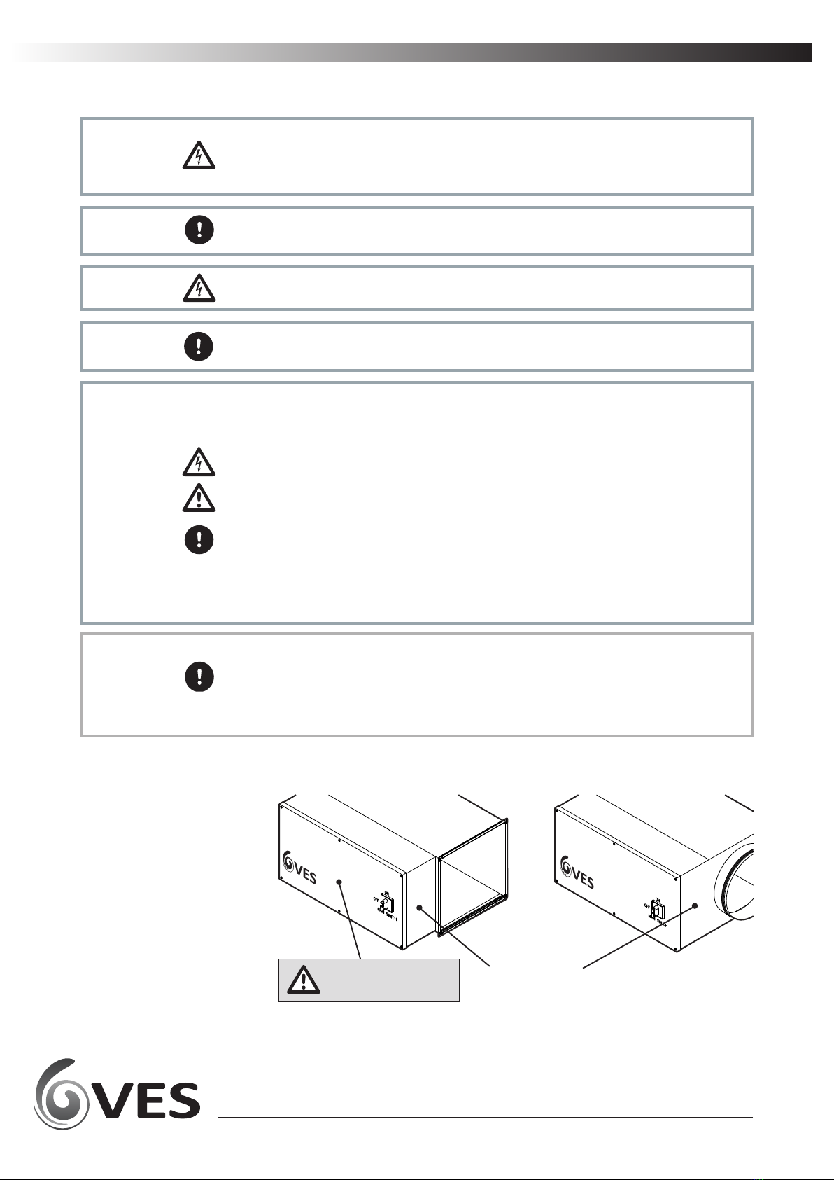
When moving the unit, handle with care and in such a manner
as to avoid damaging the external finish as this may reduce
the ability to reduce corrosion. Units are to be rigged and
lied using spreaders, taking into account the weight of the
unit, and liing gear should be arranged so as not to bear on
the casework see right.
Cauon Lids, housing and coil connecons must NOT be used as liing points.
Cauon
Where units have been supplied, without feet fied, take all necessary measures &
precauons to ensure the unit is fully supported and does not rely on adjoining ductwork
for full weight bearing.
Only experienced fitters should undertake this w ork. Take necessary safety precauons
when working in elevated posions.
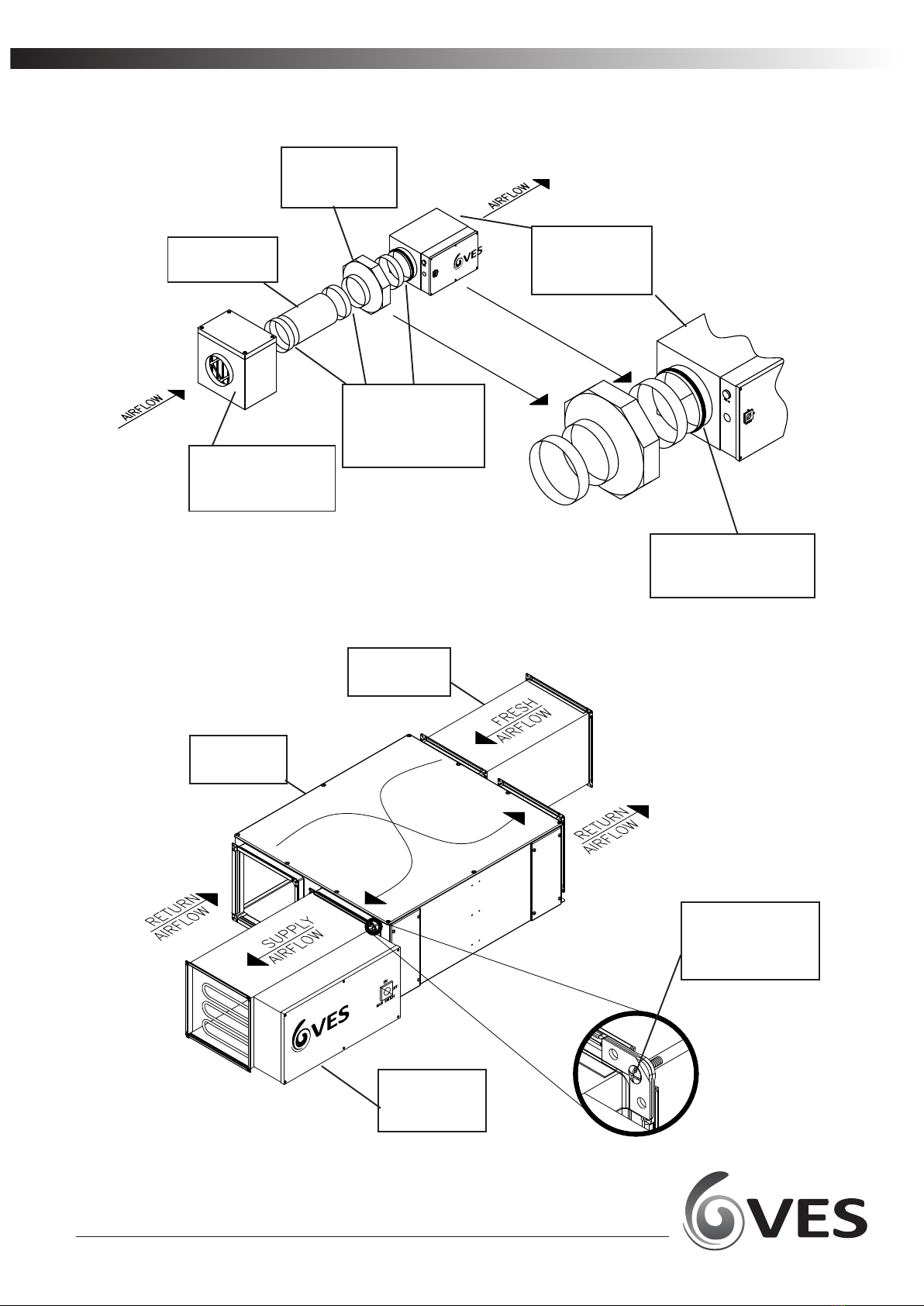
5.1 Orientaon
Installaon 5
Correct
Not suitable
Not suitable
AIRFLOW
AIRFLOW
AIRFLOW Eagle Close,
Chandlers Ford Ind. Estate,
Chandlers Ford, Eastleigh,
Hampshire, SO53 4NF
Tel: (08702) 404340
Fax: (08702) 404550
Web: www.ves.co.uk
MODEL
SUPPLY
MAX. PERMISSIBLE LOAD
VES REF.
PLANTREF.
HLC200/3KW/1X1/CP
230V 1PH 50Hz 400V 3PH 50Hz
N/AA @ 230V 26.0A @ 400V
S/O. SERIALNo. PRA4143767
INSPECTED 18/10/10 ED
Eagle Close,
Chandlers Ford Ind. Estate,
Chandlers Ford, Eastleigh,
Hampshire, SO53 4NF
Tel: (08702) 404340
Fax: (08702) 404550
Web: www.ves.co.uk
MODEL
SUPPLY
MAX. PERMISSIBLE LOAD
VES REF.
PLANTREF.
HLC200/3KW/1X1/CP
230V 1PH 50Hz 400V 3PH 50Hz
N/AA @ 230V 26.0A @ 400V
S/O. SERIALNo. PRA4143767
INSPECTED 18/10/10 ED
VESANDOVER LTD
Eagle Close,Chandlers Ford Ind. Est.,
Eastleigh,Hampshire, SO53 4NF
Tel: 08448-15-60-60
ELECTRIC HEATER
VESANDOVER LTD
Eagle Close,Chandlers Ford Ind. Est.,
Eastleigh,Hampshire, SO53 4NF
Tel: 08448-15-60-60
ELECTRIC HEATER
VESANDOVER LTD
Eagle Close,Chandlers Ford Ind. Est.,
Eastleigh,Hampshire, SO53 4NF
Tel: 08448-15-60-60
ELECTRIC HEATER
WARNING: DISCONNECT THE MAINS SUPPLY
BEFORE REMOVING THIS COVER
WARNING: DISCONNECT THE MAINS SUPPLY
BEFORE REMOVING THIS COVER
WARNING: DISCONNECT THE MAINS SUPPLY
BEFORE REMOVING THIS COVER
KW
KW
KW
X
X
X
PHASE
STEPS
PHASE
STEPS
PHASE
STEPS
SUPPLY
VOLTS
SUPPLY
VOLTS
SUPPLY
VOLTS
MIN.AIR
VOLUME
MIN.AIR
VOLUME
MIN.AIR
VOLUME
m³/SEC
m³/SEC
m³/SEC
REF.
REF.
REF.
AIRFLOW
AIRFLOW
AIRFLOW
AIRFLOW
AIRFLOW
AIRFLOW
AIRFLOW
AIRFLOW
AIRFLOW
AIRFLOW
AIRFLOW
AIRFLOW
Connued

6
heatline Duct mounted Heaters
Duct Installaon
Circular ducng
Square ducng
6Examples for illustrave purposes only
HLC****
Heatline c/w
circular spigots
RS***
Fan c/w
circular spigots
Ducng where
necessary
EBXEX****
Male & Female
couplings where
necessary
Self sealing spigot
as standard on sizes
up to Ø560 mm
CRSM****
Filter secon
c/w circular spigots
ECO***
Ecobox unit
HLD****
Heatline c/w
square spigots
Ducng where
necessary
Securing nuts &
bolts used to join
30 mm MEZ flanges
together

7
heatline Duct mounted Heaters
Duct Installaon 6
For sensive installaons, VES can offer a 4 to 20 mA control opon.
Important
Fan run on sequence determined by BMS.
Warning
To ensure safety and compliance, please refer to O&M manual for wiring, fan run-on, and
installaon instrucons.
Warning
6.1 Airflow
Cauon The heater can be used for horizontal or vercal airflow. The air should be evenly
distributed across the duct and the minimum air volume as stated on the air heater name
plate must be maintained.
6.2 Thermal
Cutout (Auto)
(EHB opon only)
Every heater is provided with a thermal cutout which will break contacts when the duct
temperature rises above 70 °C. This cutout is provided to comply with M & E specificaons
and will require removal of the terminal cover to reset.
Supply must be isolated before removing cover.
Warning
N.B. It is very important that all electrical connecons are properly made. Elements are
tested prior to dispatch and are within tolerance of ±7½ W of total load. If the elements are
found to be faulty they can be easily removed and replaced. Elements stored in damp
condions may need drying to aain correct insulaon readings - contact VES Andover Ltd. if
in doubt.
6.3 Tesng
(EHB opon only)
Connued
•Supply to Heatline should be 1ph or 3ph and a neutral - refer to name plate for
correct supply.
•The heater is fied with a manual reset high temperature cutout which has NC
(normally closed) terminals and an air flow pressure switch. This is connected in
series with the main contactor coil circuit, to remove power from the heater in the
event of over-temperature or airflow failure. Under no circumstances is this circuit to
be by passed.
•Ensure sufficient earth connecon to terminal is provided.
•The speed controller must not switch off fan independent of control system or
allow airflo w to fall below stated volume on the electric he ater baery.
•Fan run on mer r equired. Turn off 0-10 V heat demand signal 2 minut es before fan
enable signal.
•Separate cables should be ins talled for 0-10 VDC, Control signal and 24 VAC switched
enable signal in c ompliance BS7671/2018.
6.4 Notes
(EHB opon only)
Warning
Cauon
Important

8
heatline Duct mounted Heaters
Coil Installaon 7 Coils should be piped according to any relevant local codes of pracce. Where threaded
connecons are supplied, the only approved method of joinng is by use of Boss white and
hemp. The thread fied to the coil is to be supported at all mes whilst making joints. All
external piping is to be supported independently from the coil. Fluid filters are
recommended.
It is important that water and steam coils are protected against damage from extreme
weather condions during the winter season. If the water is allowed to freeze in the coil
system, damage may occur potenally bursng pipes and resulng in emergency problems.
Fing a frost thermostat at the unit inlet and ensuring that boilers run connuously in low
ambient temperatures can help to prevent this.
Heang c oils do not c ool immediately when the hot w ater supply is turne d off. The residual
heat must be dissipated to avoid damage. The connuous running of the fan aer
shutdown resolves this, by operaon of a run-on mer; the recommended length of run-on
is 2 minutes minimum.
On HeatLine units, a Low Pressure Hot Water (LPHW) coil will be installed. Coils are normally
suitable for LPHW at 82 °C flow and 71 °C return temperature. LPHW coils are supplied as
standard with an air vent and drain plug located on the pipe work immediately adjacent to
the coil connecon. The air vent should be at the highest point, with the drain at the
lowest. The coil should be regularly vented so as to avoid potenal air locks, resulng in a
fall off of duty.
It is recommended that a check be made as to whether any treatment is required to the
water supply for prevenon of corrosion and scaling of the equipment. Informaon
regarding the necessary acon to be taken can be obtained from the relevant Local Water
Supply Authority.
The unit will have been supplied with connecons either le or right-hand side looking in
direcon of airflo w. Please see order acknowledgment for confirmaon of this handing.
Should you need to alter this please consult VES Andover Ltd as unit adjustment may
invalidate your warranty.
LPHW units feature a coil connecon c over. To access during ins tallaon c arefully remove
the cover by unfastening the fixings ar ound the cover. Holes have been provided in the
housing base for pipe w ork entry. Please follow the appropriate manufacturer’s instrucon
carefully when fit ng a v alve actuator. Ensure that the cover and fixings ar e replaced upon
compleon.

9
heatline Duct mounted Heaters
Wiring 8
Warning Do not connect any unit to an electrical supply voltage outside of the specificaon.
This document refers to 0-10 V control input.
In some cases a 4-20 mA control input may have been provided.
Important
•Supply to Heatline should be 1ph or 3ph and a neutral - refer to name plate for
correct supply.
•The heater is fied with a manual reset high temperature cutout which has NC (normally
closed) terminals and an air flow pressure switch. This is connected in series with the
main contactor coil circuit, to remove power from the heater in the event of over-
temperature or airflow failure. Under no circumstances is this circuit to be by passed.
•Ensure sufficient earth connecon to terminal is provided.
•The speed controller must not switch off fan independent of control system or allow
airflow to fall below stated volume on the electric he ater baery.
•Fan run on mer r equired. Turn off 0-10 V heat demand signal 2 minut es before fan
enable signal.
•Separate cables should be ins talled for 0-10 VDC, Control signal and 24 VAC switched
enable signal in c ompliance BS7671/2018.
Warning
Cauon
Important
The electrical supply must be fully isolated before aempng to affect any work on this unit.
All electrical connecons to any unit must be carried put in accordance with the current
edion of the I.E. T Regulaons, only c ompetent Electricians should be allo wed to affect any
electrical work to our units.
Warning
It is the cus tomer’s responsibility to supply earth fault protecon through the bui lding
installaon device and a dedicated, isolated power supply with overload protecon.
Important
It is recommended that the cable entry point should be at the end of the control
secon as shown in the figur e below.
It is the responsibility of the installer to ensure that a suitable cable gland (giving
adequate protecon and strain relief) is fied, and in doing so also ensure that no
internal components are damaged during this installaon. Make certain all swarf is
removed before use.
Important
Recommended
cable entry point
Recommended cable
entry point
Remove Cover before
making cable entry.

10
heatline Duct mounted Heaters
8.1 BMS 1ph
example wiring
diagram
Wiring 8 Connued
The following wiring diagrams are a guide to installing the standard fan and actuator
opons found on Heatline units. If in any doubt, for units with fied VES controls or for
special versions of the units, consult the wiring diagram in your document pack or contact VES
Customer Services Department on 02380 46 11 50, quong the sales order (SO) number and
unit type as found on the unit name plate.
Note: Please refer to order
acknowledgement for specific controls
wiring informaon and heater load.
Warning Cauon Important

11
heatline Duct mounted Heaters
Wiring 8
8.2 CP 1ph example
wiring diagram
Connued
Note: Please refer to order
acknowledgement for specific controls
wiring informaon and heater load.
Warning Cauon Important

12
heatline Duct mounted Heaters
8.3 LPHW BMS
example wiring
diagram
Note: Please refer to order
acknowledgement for specific controls
wiring informaon and heater load.
Warning Cauon Important
Wiring 8 Connued

13
heatline Duct mounted Heaters
8.4 LPHW CP
example wiring
diagram
Note: Please refer to order
acknowledgement for specific controls
wiring informaon and heater load.
Warning Cauon Important
Wiring 8 Connued

14
heatline Duct mounted Heaters
Controls
9.1 CP Opon Operaon
Layout
Buon Operaon •When the thermostat is in normal operaon, the actual operang mode and status
are indicated by symbols.
•When a buon is pressed, the RDG goes into mode selecon.
•The LCD backlight will turn on, all possible mode selecon opons (symbols) will
turn on, indicator element (arrow) will appear on the current mode/status.
•When the buon is pressed again, the indicator element will change to the next
mode symbol and so on.
•Aer the last press and a me-out of 3 seconds, the newly selected mode is
confirmed, the other elemen ts disappear.
•Aer a me-out of 2 0 seconds, the LCD backlight will turn off.
1 Operang mode buon / Esc
2 Buon to enter the me and to set the mers
3 Fan mode buon / OK
4 Rotary knob for setpoint and parameter adjustment
9

15
heatline Duct mounted Heaters
Controls 9
AUTO
AUX
AUTO
AUTO
pm
am
%r.HF
C
F
C
6
5
4
3
24 23 22 21 20 19
16
15
8
8
131211
10
97
14
2
118
17
#Symbol Descripon # Symbol Descripon
Heang mode Automac fan
Electrical heater on Manual fan
Cooling mode Fan speed 1
Comfort mode Fan speed Fan speed 2
Energy Saving mode Fan speed 3
Auto Timer mode Degrees Celsius
Degrees Fahrenheit
View & set auto mer program
Protecon Digits for room temperature and setpoint display
Escape Buon lock
Digits for me of day, room
temperature, setpoint etc. Condensaon in room (dewpoint sensor acve)
Seng the me of day and the
weekday Weekday 1....7:1 = Monday /7 = Sunday
Morning:12-hour format
Aernoon: 12-hour format
Fault
Temporary mer funcon (visible when
operang mode is temporary extended due to
presence or absence)
Confirmaon of parameters Indicates that room temperature is displayed
AUTO
AUX
pm
am
pm
am
AUTO
F
C
F
C
8
6
5
4
3
2
1
24
23
22
21
20
19
18
17
16
15
14
13
12
11
10
9
7
Connued

16
heatline Duct mounted Heaters
9.2 Brief description •Controls for modulang thyristor electric heater.
•2 mulfunconal inputs and 1 digital input for keycard contact, external
sensor, etc.
•Operang modes: Comfort, Energy Saving and Protecon.
•Adjustable commissioning and control parameters.
•Minimum and maximum setpoint limitaon.
•Backlit LCD.
•Auto Timer mode with 8 programmable mers.
•7-day me program: 8 programmable mers to switch over between Comfort
and Energy Saving mode.
•Maintenance of room temperature via built-in temperature sensor or external
room temperature / return air temperature sensor.
•Display of current room temperature or setpoint in °C and/or °F.
•Buon lock (automac or manual).
•Fault input.
•Reminder to clean filters.
•Reload factory sengs for commissioning control parameters.
9.2.1 Applicaons
9.2.2 Features
Do not mount on a wall in niches, bookshelves,
behind curtains, above or near heat sources, or
exposed to direct solar radiaon.
Mount about 1.5 m above the floor.
9.3 Mounng and
installaon
Warning
Cauon
Important
• The room unit must be mounted in a clean, dry indoor place and must not be
exposed to water.
• Comply with local regulaons to wire, fuse and earth the thermostat.
• Use the correct size cables for the duct EHB controller and room unit.
• The power supply line must have an external fuse or circuit breaker with a rated
current to meet the required heater full load current.
• Isolate the cables of inputs X1-M / X2-M and D1-GND if the conduit box carries AC
230 V mains voltage.
• Inputs X1-M and X2-M c arry mains potenal. If the sensor ’s cables are extended,
they must be suited for mains voltage.
• Inputs X1-M, X2-M or D1-GND of different units (e.g. summer / winter switch) may be
connected in parallel with an external switch. Consider overall maximum contact
sensing current for switch rang.
• Disconnect power supply before removing the thermostat from the mounng plate!
Controls 9 Connued

17
heatline Duct mounted Heaters
9.3 Mounng and
installaon connued
Select the applicaon and the type of control output via the DIP switches before fing the
thermostat to the mounng plate. Aer power is applied, the thermostat carries out a reset
during which all LCD segments blink, indicang that the reset was correct. Aer the reset,
which takes about 3 sec onds, the thermostat is ready for commissioning by qualified HVAC
staff. Refer to secon 7.4
The control parameters of the thermostat can be set to ensure opmum performance of the
enre system. See page 15 to find out how to set.
Commissioning
Control sequence
Calibrate sensor
Setpoint and
setpoint seng
range limitaon
9.4 Control sequences
The control sequence may need to be set via parameter P01 depending on the applicaon.
The factory seng is P01= 0 (heang only)
Recalibrate the temperature sensor if the room temperature displayed on the thermostat
does not match the room temperature measured. To do this, change parameter P05.
We recommend to review the setpoints and setpoint seng ranges (parameters P08…P12)
and change them as needed to achieve maximum comfort and save Energy
9.4.1
Sequences
overview
(seng via
parameter P01)
The sequence can be set via parameter P01. The thermostats can be used in systems
featuring:
• Heang only (P01=0)
9.4.2 Controls
output overview
(seng via DIP
switches)
The paerns of DIP switches is as follows:
Y1/Y2= 2-posion
Important
Parameter
Sequence
Mode
Heang mode
P01=0
ON
OFF
2 3 41 5
Controls 9 Connued

18
heatline Duct mounted Heaters
9.5 Fan control The HLS/HLD unit has single speed fan control only.
The clean fan filter reminder funcon counts the fan operang hours and displays message
“FIL” to remind the user t o clean the fan fi lter as soon as the threshold is reached. This
does not impact the thermostat’s operaon, which c onnues to run normally.
The clean filter reminder is reset when the operang mode is manually set to Protecon
and back. See secon 9.1
Clean Filter
Fan operaon in
AutoTimer
In Auto Timer mode, the default fan mode is aut omac. The fan mode can be changed to
manual by pushing the “FAN” button. The fan returns to the automac default mode aer
each switchover from Comfort to Energy Saving mode and vice versa.
When the electrical heater is switched off, the fan overruns for at least 3 minutes (param-
eter P54 factory set by VES) to avoid over temperature of the electrical heater or prevent the
thermal cutout from responding. In case of fan failure, the thermostat cannot protect the
electrical heater against over temperature. That is why the electrical heater features a
separate safety device (thermal cutout).
Note: For the BMS opon the fan run on must be controlled by others
Fan overrun for
EHB unit
(CP opon only)
Caution
9.6 AutoTimer The thermostat provides an Auto T imer mode with 8 programmable mers. Each mer c an
be assigned to one or several days. In this mode, the thermostat automacally changes
over between Comfort and Energy Saving mode according to the preprogrammed mers.
Seng me of day
and the weekday
1. Press the program mode buon to enter the programming mode menu.
2. Press button (OK) to enter the setng mode for the me of da y. The me digit s start
blinking.
3. Turn the rotary knob clock- or counterclockwise to set the me of day. 12Hr or 24Hr
me format:
AUTO
C
AUTO
C
AUTO
AUTO
12 3
AUTO
AUTO
4 6 75
Controls 9 Connued

19
heatline Duct mounted Heaters
12 and 24-hour
format
Power failure
Default mer seng
If the current me of day is in 24-hour format and you wish to change it to 12-hour format, turn
the knob clockwise passed 23:59 or counterclockwise passed 00:00. If the current me of day is
in 12-hour format and you wish to change it to 24-hour format, turn the knob clockwise passed
12:00 pm or counterclockwise passed 12:00am.
4. Confirm the me of day by pressing the right buon. The weekday indicator starts blinking.
5. Turn the rotary knob clock- or counterclockwise to set the current weekday.
6. Confirm the current weekday by pressing buon (OK).
7. Press the program mode buon (Esc) to leave the program mode.
Timers A1…A4 have the following default setngs (r esidenal use):
Aer a power failure, the me of day will blink to indicate power was lost. However the
auto mer will connue to run with the me before the power loss occurred. Enter the
seng mode to adjust the me of day if needed.
Days Time when thermostat is in Comfort mode
Mon (1)-Fri (5) 06:30-08:30 (A1) 17:30-22:30 (A2)
Sat (6) 08:00-23:00 (A3)
Sun (7) 08:00-22:30 (A4)
Ÿ
Ÿ
The thermostat is in Energy saving mode during the remaining me
Timers A5...A8 are free with no default sengs
9.6 AutoTimer
Controls 9 Connued

20
heatline Duct mounted Heaters
9.6 AutoTimer
Connued
Seng the mers
The CP opon provides 8 programmable mers A1 … A8. Each mer has a Comfort mode start
and end me that can be applied to one or several weekdays.
You can view the 8 mers in sequence:
1. Press the program mode button twice to select the “Auto mer se tng ” in
programming mode.
2. Turn the rotary knob to review the 8 auto mers.
3. Press buon (Esc) to return to normal operaon.
Viewing the
mers
To set an auto mer, proceed as follows:
1. Press the program mode button twice to select “Auto mer setng” on the
“Programming mode” menu.
2. Turn the rotary knob to the desired mer A1…A8 that you wish to adjust and press
buon (OK).
3. Turn the rotary knob to adjust the Comfort mode start me and confirm by
pressing buon (OK).
4. Turn the rotary knob to adjust the Comfort mode end me or Ener gy Saving start
me respecvely and confirm by pressing buon (OK)
5. Weekday, and blink. Press button (OK) to select or button (Esc) to deselect each
day and advance to the next day.
6. Aer the 7th day is adjusted, all selected weekdays blink.
Confirm seng for actual mer by pressing buon (OK) and advance to the next
mer. To adjust the next mer, repeat step 3…6 or press button (Esc) to leave the
seng mode.
To save your adjustments, remember to press button (OK) in s tep 6 above
before pressing buon (Esc) to leave the programmable mer seng mode.
AUTO
C
AUTO
AUTO
123
AUTO
C
AUTO
AUTO
AUTO
AUTO
AUTO AUTO
1 2 3 4
5 6 7
Controls 9 Connued
Table of contents
Popular Camera Accessories manuals by other brands

KiloVault
KiloVault HAB V3 Addendum Installation and operation manual

ARRI
ARRI 12xT1.3 brochure

Panasonic
Panasonic GP-US932CSXE operating instructions

Power Storage Solutions
Power Storage Solutions 12MQ1200 Installation, operation and maintenance manual

Manfrotto
Manfrotto 745XB instructions

Minolta
Minolta VC-7 - IR REMOTE CONTRO LRC-3 manual