VES Heatline User manual

1
Heatline - Duct mounted Heater with controls
Installation, Operation and Maintenance Manual
VES Andover Ltd. Eagle Close, Chandlers Ford Ind. Est, Eastleigh, Hampshire, SO53 4NF
Tel: 08448 15 60 60 Fax: 02380 26 12 04 E-mail: vesltd@ves.co.uk Web: www.ves.co.uk
Please ensure that this document is passed to the end user. This manual forms an integral
part of the product and should be kept for the working life of the product. Additional copies
of this and supporting documents are available by contacting VES Andover Ltd or by visiting
www.ves.co.uk and following the ‘Information centre O & M’s’ link.
This manual must be read in full before installation, operation and maintenance of the units.
Important
The following symbols used within this document refer to potential dangers or advice for
safe operation.
Indicates hazards associated with electric current and high voltages.
Indicates hazards that require safety advice for personnel and/or potential unit/property
damage.
Warning
Caution
Important Indicates important information.
Contents
1
2
3
4
5
6
7
8
9
10
11
12
Page
Introduction.................................................................................................................. 2
Unit Description........................................................................................................... 2
Receipt of Goods/Handling........................................................................................2
Product Overview ......................................................................................................... 3
Installation ................................................................................................................. 3
Duct Installation.......................................................................................................... 5
Coil Installation........................................................................................................... 7
Wiring............................................................................................................................ 8
Controls........................................................................................................................ 13
Maintenance .............................................................................................................. 32
Declaration of Conformity..........................................................................................33
Warranty....................................................................................................................... 34
ORIGINAL INSTRUCTIONS
VES Ref: ID 899 Issue: E
August 2014

ORIGINAL INSTRUCTIONS
2
Heatline - Duct mounted Heater with controls
Installation, Operation and Maintenance Manual
VES Andover Ltd. Eagle Close, Chandlers Ford Ind. Est, Eastleigh, Hampshire, SO53 4NF
Tel: 08448 15 60 60 Fax: 02380 26 12 04 E-mail: vesltd@ves.co.uk Web: www.ves.co.uk
Unit Description
Typical example
2
Part Number Coding
The VES HEATLINE Duct Mounted Heater Battery brings wider versatility to existing and new
ventilation installations. Intelligent control options for BMS or LCD room units, plus a
Thyristor (EHB option) /Valve actuator (LPHW option) heater make this the ideal solution to
accurately heat individual rooms. HEATLINE is also both simple to install and maintain.
Duct sizes form a slow as 100 Square/Round on EHB, 200 Square/Round on LPHW. Operating
temperature -20 to 70 ºC.
Introduction
For further technical details regarding dimensions and weights, contact VES Andover Ltd on
08448 15 60 60, quoting the sales order (SO) number and the unit type as found on the unit
nameplate or visit www.ves.co.uk.
1
Immediately upon receipt of goods, check for possible damage in transit.
Also check to ensure that any ancillary items are included. These will normally be
supplied fitted or taped to the unit (in the case of small items).
In the event of any damage having occurred or if any item found to be missing, it is
essential to inform VES Andover Ltd. within 3 working days of delivery quoting sales
order (SO) number and the unit type as found on the unit nameplate. After this period
we will be unable to accept any claim for damaged or missing goods.
Receipt of Goods
& Handling
3
Point Description Point Variants
Product HLD
HLC
HLS
Square Ducting
Circular Ducting
Square Ducting Stab-in
1
Duct Size 100 to 600
100 to 600
Diameter size for circular ducting
Lengths of sides for square ducting
2
Config /Null
/W
Plantroom
Weatherproof
3
Heating 0.5 to 32
/W
KW rating
Coil
4
Thyristor Heater Supply /Null
1x1
1x3
1 Phase
3 Phase
5
Control Options BMS
CP
V/F enabled and 0-10V heat demand
control from remote source
LCD room unit control
6
Details (as appropriate)
EHB
HLC/ 200/ 4.5KW/ 1X1/ CP
1 2 3 5 6
LPHW
HLD/ 450/ W/ W/ BMS
1 2 3 4 6

ORIGINAL INSTRUCTIONS
3
Heatline - Duct mounted Heater with controls
Installation, Operation and Maintenance Manual
VES Andover Ltd. Eagle Close, Chandlers Ford Ind. Est, Eastleigh, Hampshire, SO53 4NF
Tel: 08448 15 60 60 Fax: 02380 26 12 04 E-mail: vesltd@ves.co.uk Web: www.ves.co.uk
Product Overview 4
Use with VES ECOBOX, filter and fan kits for compact, efficient heat recovery. (Refer to page 5).
External control
Control option 1 - BMS V/F enabled and 0-10 V dc control (no room unit).
minutes before V/F system run signal is removed.
Control option 2 - LCD Room Unit
As control option 1 PLUS...
4.2 Control types
4.2.1 BMS
4.2.2 CP
The entire system must be considered for safety purposes and it is the responsibility of the
installer to ensure that all of the equipment is installed to compliance with the
manufacturer’s recommendations, with due regard to the current HEALTH AND SAFETY AT
WORK ACT and conforms to all relevant statutory regulations.
ensure that access panels are not obstructed in any way and safe working access for
maintenance must be provided in accordance with the Health and Safety, and Building
Regulations. For confirmation of required access please see the appropriate unit outline
drawing.
Consideration must also be given by the installer for adequate illumination of the unit
location in order for safe maintenance. Further consideration should be given to the unit’s
position and secured into place as appropriate. This is especially important with external
mounting as the wind and elements may effect overall stability.
Installation 5
4.1 Features

ORIGINAL INSTRUCTIONS
4
Heatline - Duct mounted Heater with controls
Installation, Operation and Maintenance Manual
VES Andover Ltd. Eagle Close, Chandlers Ford Ind. Est, Eastleigh, Hampshire, SO53 4NF
Tel: 08448 15 60 60 Fax: 02380 26 12 04 E-mail: vesltd@ves.co.uk Web: www.ves.co.uk
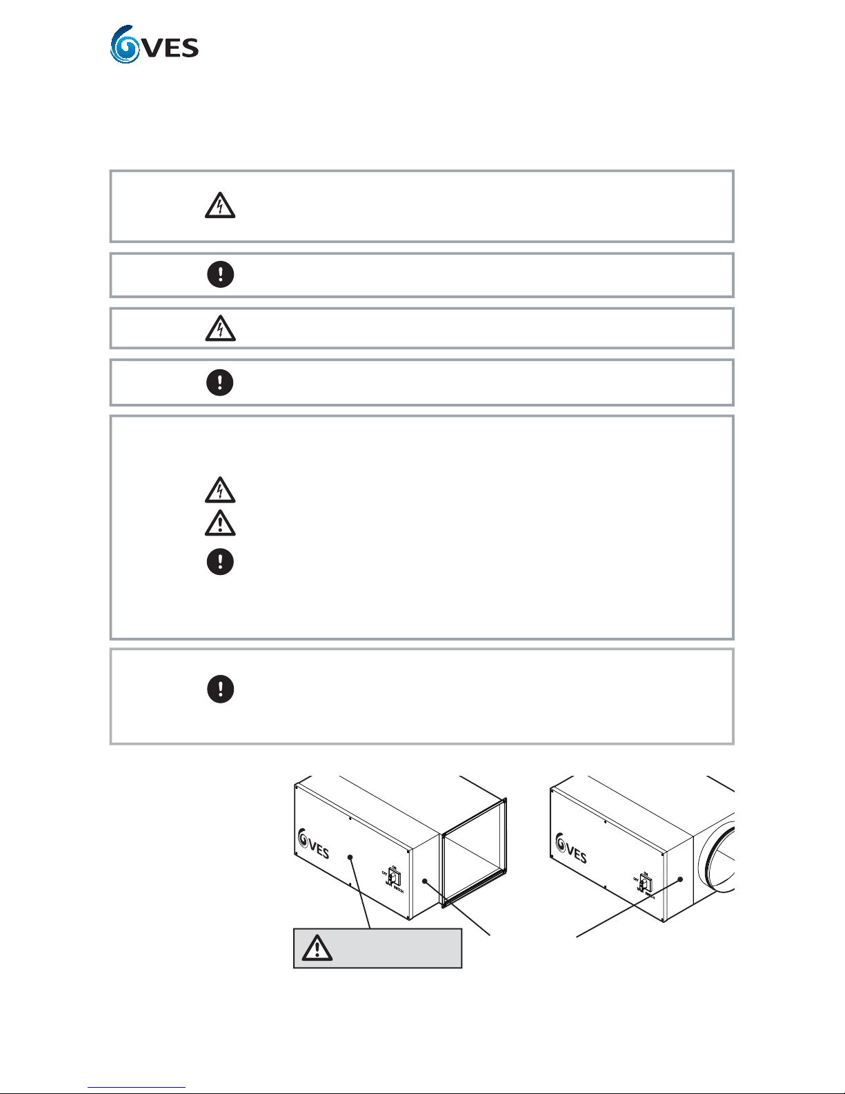
When moving the unit, handle with care and in such a manner
as to avoid damaging the external finish as this may reduce
the ability to reduce corrosion. Units are to be rigged and
lifted using spreaders, taking into account the weight of the
unit, and lifting gear should be arranged so as not to bear on
the casework see right.
Caution Lids, housing and coil connections must NOT be used as lifting points.
Caution
Where units have been supplied, without feet fitted, take all necessary measures &
for full weight bearing.
Only experienced fitters should undertake this work. Take necessary safety precautions
when working in elevated positions.
5.1 Orientation
Installation 5
Correct
Not suitable
Not suitable
AIRFLOW
AIRFLOW
AIRFLOW
EagleClose,
ChandlersFord Ind. Estate,
ChandlersFord, Eastleigh,
Hampshire,SO53 4NF
Tel:(08702) 404340
Fax:(08702) 404550
Web:www.ves.co.uk
MODEL
SUPPLY
MAX.PERMISSIBLE LOAD
VESREF.
PLANTREF.
HLC200/3KW/1X1/CP
230V1PH 50Hz 400V3PH 50Hz
N/AA @ 230V 26.0A @ 400V
S/O. SERIALNo. PRA4143767
INSPECTED 18/10/10 ED
VESANDOVER LTD
EagleClose,Chandlers Ford Ind. Est.,
Eastleigh,Hampshire,SO53 4NF
Tel:08448-15-60-60
ELECTRIC HEATER
VESANDOVER LTD
EagleClose,Chandlers Ford Ind. Est.,
Eastleigh,Hampshire,SO53 4NF
Tel:08448-15-60-60
ELECTRIC HEATER
VESANDOVER LTD
EagleClose,Chandlers Ford Ind. Est.,
Eastleigh,Hampshire,SO53 4NF
Tel:08448-15-60-60
ELECTRIC HEATER
WARNING:DISCONNECT THE MAINS SUPPLY
BEFORE REMOVING THIS COVER
WARNING:DISCONNECT THE MAINS SUPPLY
BEFORE REMOVING THIS COVER
WARNING:DISCONNECT THE MAINS SUPPLY
BEFORE REMOVING THIS COVER
KW
KW
KW
X
X
X
PHASE
STEPS
PHASE
STEPS
PHASE
STEPS
SUPPLY
VOLTS
SUPPLY
VOLTS
SUPPLY
VOLTS
MIN.AIR
VOLUME
MIN.AIR
VOLUME
MIN.AIR
VOLUME
m³/SEC
m³/SEC
m³/SEC
REF.
REF.
REF.
AIRFLOW
AIRFLOW
AIRFLOW
AIRFLOW
AIRFLOW
AIRFLOW
AIRFLOW
AIRFLOW
AIRFLOW
AIRFLOW
AIRFLOW
AIRFLOW
Continued

ORIGINAL INSTRUCTIONS
5
Heatline - Duct mounted Heater with controls
Installation, Operation and Maintenance Manual
VES Andover Ltd. Eagle Close, Chandlers Ford Ind. Est, Eastleigh, Hampshire, SO53 4NF
Tel: 08448 15 60 60 Fax: 02380 26 12 04 E-mail: vesltd@ves.co.uk Web: www.ves.co.uk
Duct Installation
Circular ducting
Square ducting
6Examples for illustrative purposes only
HLC****
Heatline c/w
circular spigots
RS***
Fan c/w
circular spigots
Ducting where
necessary
EBXEX****
Male & Female
couplings where
necessary
Self sealing spigot
as standard on sizes
up to Ø560 mm
CRSM****
Filter section
c/w circular spigots
ECO***
Ecobox unit
HLD****
Heatline c/w
square spigots
Ducting where
necessary
Securing nuts &
30 mm MEZ flanges
together

ORIGINAL INSTRUCTIONS
6
Heatline - Duct mounted Heater with controls
Installation, Operation and Maintenance Manual
VES Andover Ltd. Eagle Close, Chandlers Ford Ind. Est, Eastleigh, Hampshire, SO53 4NF
Tel: 08448 15 60 60 Fax: 02380 26 12 04 E-mail: vesltd@ves.co.uk Web: www.ves.co.uk
Duct Installation 6
For sensitive installations, VES can offer a 4 to 20 mA control option.
Important
Fan run on sequence determined by BMS.
Warning
To ensure safety and compliance, please refer to O&M manual for wiring, fan run-on, and
installation instructions.
Warning
6.1 Airflow
Caution The heater can be used for horizontal or vertical airflow. The air should be evenly
distributed across the duct and the minimum air volume as stated on the air heater name
plate must be maintained.
6.2 Thermal
Cutout (Auto)
(EHB option only)
Every heater is provided with a thermal cutout which will break contacts when the duct
temperature rises above 70 °C. This cutout is provided to comply with M & E specifications
and will require removal of the terminal cover to reset.
Supply must be isolated before removing cover.
Warning
N.B. It is very important that all electrical connections are properly made. Elements are
tested prior to dispatch and are within tolerance of ±7½ W of total load. If the elements are
found to be faulty they can be easily removed and replaced. Elements stored in damp
conditions may need drying to attain correct insulation readings - contact VES Andover Ltd. if
in doubt.
6.3 Testing
(EHB option only)
Continued
Supply to Heatline should be 1ph or 3ph and a neutral - refer to name plate for
correct supply.
The heater is fitted with a manual reset high temperature cutout which has NC
(normally closed) terminals and an air flow pressure switch. This is connected in
series with the main contactor coil circuit, to remove power from the heater in the
event of over-temperature or airflow failure. Under no circumstances is this circuit to
be by passed.
Ensure sufficient earth connection to terminal is provided.
The speed controller must not switch off fan independent of control system or
allow airflow to fall below stated volume on the electric heater battery.
Fan run on timer required. Turn off 0-10 V heat demand signal 2 minutes before fan
enable signal.
Separate cables should be installed for 0-10 VDC, Control signal and 24 VAC switched
enable signal in compliance BS7671/2008.
6.4 Notes
(EHB option only)
Warning
Caution
Important

ORIGINAL INSTRUCTIONS
7
Heatline - Duct mounted Heater with controls
Installation, Operation and Maintenance Manual
VES Andover Ltd. Eagle Close, Chandlers Ford Ind. Est, Eastleigh, Hampshire, SO53 4NF
Tel: 08448 15 60 60 Fax: 02380 26 12 04 E-mail: vesltd@ves.co.uk Web: www.ves.co.uk
Coil Installation 7 Coils should be piped according to any relevant local codes of practice. Where threaded
external piping is to be supported independently from the coil. Fluid filters are
recommended.
It is important that water and steam coils are protected against damage from extreme
weather conditions during the winter season. If the water is allowed to freeze in the coil
system, damage may occur potentially bursting pipes and resulting in emergency problems.
Fitting a frost thermostat at the unit inlet and ensuring that boilers run continuously in low
ambient temperatures can help to prevent this.
Heating coils do not cool immediately when the hot water supply is turned off. The residual
heat must be dissipated to avoid damage. The continuous running of the fan after
shutdown resolves this, by operation of a run-on timer; the recommended length of run-on
is 2 minutes minimum.
On HeatLine units, a Low Pressure Hot Water (LPHW) coil will be installed. Coils are normally
suitable for LPHW at 82 °C flow and 71 °C return temperature. LPHW coils are supplied as
the coil connection. The air vent should be at the highest point, with the drain at the
lowest. The coil should be regularly vented so as to avoid potential air locks, resulting in a
fall off of duty.
It is recommended that a check be made as to whether any treatment is required to the
water supply for prevention of corrosion and scaling of the equipment. Information
regarding the necessary action to be taken can be obtained from the relevant Local Water
Supply Authority.
The unit will have been supplied with connections either left or right-hand side looking in
direction of airflow. Please see order acknowledgment for confirmation of this handing.
invalidate your warranty.
LPHW units feature a coil connection cover. To access during installation carefully remove
the cover by unfastening the fixings around the cover. Holes have been provided in the
housing base for pipe work entry. Please follow the appropriate manufacturer’s instruction
carefully when fitting a valve actuator. Ensure that the cover and fixings are replaced upon
completion.

ORIGINAL INSTRUCTIONS
8
Heatline - Duct mounted Heater with controls
Installation, Operation and Maintenance Manual
VES Andover Ltd. Eagle Close, Chandlers Ford Ind. Est, Eastleigh, Hampshire, SO53 4NF
Tel: 08448 15 60 60 Fax: 02380 26 12 04 E-mail: vesltd@ves.co.uk Web: www.ves.co.uk
Wiring 8
Warning Do not connect any unit to an electrical supply voltage outside of the specification.
This document refers to 0-10 V control input.
In some cases a 4-20 mA control input may have been provided.
Important
Supply to Heatline should be 1ph or 3ph and a neutral - refer to name plate for
correct supply.
The heater is fitted with a manual reset high temperature cutout which has NC (normally
closed) terminals and an air flow pressure switch. This is connected in series with the
main contactor coil circuit, to remove power from the heater in the event of over-
temperature or airflow failure. Under no circumstances is this circuit to be by passed.
Ensure sufficient earth connection to terminal is provided.
The speed controller must not switch off fan independent of control system or allow
airflow to fall below stated volume on the electric heater battery.
Fan run on timer required. Turn off 0-10 V heat demand signal 2 minutes before fan
enable signal.
Separate cables should be installed for 0-10 VDC, Control signal and 24 VAC switched
enable signal in compliance BS7671/2008.
Warning
Caution
Important
The electrical supply must be fully isolated before attempting to affect any work on this unit.
All electrical connections to any unit must be carried put in accordance with the current
edition of the I.E.E Regulations, only competent Electricians should be allowed to affect any
electrical work to our units.
Warning
It is the customer’s responsibility to supply earth fault protection through the building
installation device and a dedicated, isolated power supply with overload protection.
Important
It is recommended that the cable entry point should be at the end of the control
section as shown in the figure below.
It is the responsibility of the installer to ensure that a suitable cable gland (giving
adequate protection and strain relief) is fitted, and in doing so also ensure that no
internal components are damaged during this installation. Make certain all swarf is
removed before use.
Important
Recommended
cable entry point
Recommended cable
entry point
Remove Cover before
making cable entry.

ORIGINAL INSTRUCTIONS
9
Heatline - Duct mounted Heater with controls
Installation, Operation and Maintenance Manual
VES Andover Ltd. Eagle Close, Chandlers Ford Ind. Est, Eastleigh, Hampshire, SO53 4NF
Tel: 08448 15 60 60 Fax: 02380 26 12 04 E-mail: vesltd@ves.co.uk Web: www.ves.co.uk
8.1 BMS 1ph
example wiring
diagram
Wiring 8 Continued
The following wiring diagrams are a guide to installing the standard fan and actuator
options found on Heatline units. If in any doubt, for units with fitted VES controls or for
special versions of the units, consult the wiring diagram in your document pack or contact VES
Customer Services Department on 08448 15 60 60, quoting the sales order (SO) number and
unit type as found on the unit name plate.
Note: Please refer to order
acknowledgement for specific controls
wiring information and heater load.
Warning Caution Important

ORIGINAL INSTRUCTIONS
10
Heatline - Duct mounted Heater with controls
Installation, Operation and Maintenance Manual
VES Andover Ltd. Eagle Close, Chandlers Ford Ind. Est, Eastleigh, Hampshire, SO53 4NF
Tel: 08448 15 60 60 Fax: 02380 26 12 04 E-mail: vesltd@ves.co.uk Web: www.ves.co.uk
Wiring 8
8.2 CP 1ph example
wiring diagram
Continued
Note: Please refer to order
acknowledgement for specific controls
wiring information and heater load.
Warning Caution Important

ORIGINAL INSTRUCTIONS
11
Heatline - Duct mounted Heater with controls
Installation, Operation and Maintenance Manual
VES Andover Ltd. Eagle Close, Chandlers Ford Ind. Est, Eastleigh, Hampshire, SO53 4NF
Tel: 08448 15 60 60 Fax: 02380 26 12 04 E-mail: vesltd@ves.co.uk Web: www.ves.co.uk
8.3 LPHW BMS
example wiring
diagram
Note: Please refer to order
acknowledgement for specific controls
wiring information and heater load.
Warning Caution Important
Wiring 8 Continued

ORIGINAL INSTRUCTIONS
12
Heatline - Duct mounted Heater with controls
Installation, Operation and Maintenance Manual
VES Andover Ltd. Eagle Close, Chandlers Ford Ind. Est, Eastleigh, Hampshire, SO53 4NF
Tel: 08448 15 60 60 Fax: 02380 26 12 04 E-mail: vesltd@ves.co.uk Web: www.ves.co.uk
8.4 LPHW CP
example wiring
diagram
Note: Please refer to order
acknowledgement for specific controls
wiring information and heater load.
Warning Caution Important
Wiring 8 Continued

ORIGINAL INSTRUCTIONS
13
Heatline - Duct mounted Heater with controls
Installation, Operation and Maintenance Manual
VES Andover Ltd. Eagle Close, Chandlers Ford Ind. Est, Eastleigh, Hampshire, SO53 4NF
Tel: 08448 15 60 60 Fax: 02380 26 12 04 E-mail: vesltd@ves.co.uk Web: www.ves.co.uk
Controls
9.1 CP Option Operation
Layout
Button Operation When the thermostat is in normal operation, the actual operating mode and status
are indicated by symbols.
When a button is pressed, the RDG goes into mode selection.
The LCD backlight will turn on, all possible mode selection options (symbols) will
turn on, indicator element (arrow) will appear on the current mode/status.
When the button is pressed again, the indicator element will change to the next
mode symbol and so on.
After the last press and a time-out of 3 seconds, the newly selected mode is
confirmed, the other elements disappear.
After a time-out of 20 seconds, the LCD backlight will turn off.
1 Operating mode button / Esc
2 Button to enter the time and to set the timers
3 Fan mode button / OK
9

ORIGINAL INSTRUCTIONS
14
Heatline - Duct mounted Heater with controls
Installation, Operation and Maintenance Manual
VES Andover Ltd. Eagle Close, Chandlers Ford Ind. Est, Eastleigh, Hampshire, SO53 4NF
Tel: 08448 15 60 60 Fax: 02380 26 12 04 E-mail: vesltd@ves.co.uk Web: www.ves.co.uk
Controls 9
AUTO
AUX
AUTO
AUTO
pm
am
%r.HF
C
F
C
6
5
4
3
24 23 22 21 20 19
16
15
8
8
131211
10
97
14
2
118
17
#Symbol Description#Symbol Description
Heating mode Automatic fan
Electrical heater on Manual fan
Cooling mode Fan speed 1
Comfort mode Fan speed Fan speed 2
Energy Saving mode
Fan speed 3
Auto Timer mode Degrees Celsius
Degrees Fahrenheit
View & set auto timer program
Protection Digits for room temperature and setpoint display
Escape Button lock
Digits for time of day, room
temperature, setpoint etc. Condensation in room (dewpoint sensor active)
Setting the time of day and the
weekday Weekday 1....7:1 = Monday /7 = Sunday
Morning:12-hour format
Afternoon: 12-hour format
Fault
Temporary timer function (visible when
operating mode is temporary extended due to
presence or absence)
Confirmation of parameters Indicates that room temperature is displayed
AUTO
AUX
pm
am
pm
am
AUTO
F
C
F
C
8
6
5
4
3
2
1
24
23
22
21
20
19
18
17
16
15
14
13
12
11
10
9
7
Continued

ORIGINAL INSTRUCTIONS
15
Heatline - Duct mounted Heater with controls
Installation, Operation and Maintenance Manual
VES Andover Ltd. Eagle Close, Chandlers Ford Ind. Est, Eastleigh, Hampshire, SO53 4NF
Tel: 08448 15 60 60 Fax: 02380 26 12 04 E-mail: vesltd@ves.co.uk Web: www.ves.co.uk
9.2 Brief description Controls for modulating thyristor electric heater.
2 multifunctional inputs and 1 digital input for keycard contact, external
sensor, etc.
Operating modes: Comfort, Energy Saving and Protection.
Minimum and maximum setpoint limitation.
Backlit LCD.
Auto Timer mode with 8 programmable timers.
7-day time program: 8 programmable timers to switch over between Comfort
and Energy Saving mode.
Maintenance of room temperature via built-in temperature sensor or external
room temperature / return air temperature sensor.
Display of current room temperature or setpoint in °C and/or °F.
Button lock (automatic or manual).
Fault input.
Reminder to clean filters.
Reload factory settings for commissioning control parameters.
9.2.1 Applications
9.2.2 Features
Do not mount on a wall in niches, bookshelves,
behind curtains, above or near heat sources, or
exposed to direct solar radiation.
Mount about 1.5 m above the floor.
9.3 Mounting and
installation
Warning
Caution
Important
exposed to water.
current to meet the required heater full load current.
230 V mains voltage.
they must be suited for mains voltage.
connected in parallel with an external switch. Consider overall maximum contact
sensing current for switch rating.
Controls 9 Continued

ORIGINAL INSTRUCTIONS
16
Heatline - Duct mounted Heater with controls
Installation, Operation and Maintenance Manual
VES Andover Ltd. Eagle Close, Chandlers Ford Ind. Est, Eastleigh, Hampshire, SO53 4NF
Tel: 08448 15 60 60 Fax: 02380 26 12 04 E-mail: vesltd@ves.co.uk Web: www.ves.co.uk
9.3 Mounting and
installation continued
Select the application and the type of control output via the DIP switches before fitting the
thermostat to the mounting plate. After power is applied, the thermostat carries out a reset
during which all LCD segments blink, indicating that the reset was correct. After the reset,
which takes about 3 seconds, the thermostat is ready for commissioning by qualified HVAC
staff. Refer to section 7.4
The control parameters of the thermostat can be set to ensure optimum performance of the
entire system. See page 15 to find out how to set.
Commissioning
Control sequence
Calibrate sensor
Setpoint and
setpoint setting
range limitation
9.4 Control sequences
The control sequence may need to be set via parameter P01 depending on the application.
The factory setting is P01= 0 (heating only)
Recalibrate the temperature sensor if the room temperature displayed on the thermostat
does not match the room temperature measured. To do this, change parameter P05.
We recommend to review the setpoints and setpoint setting ranges (parameters P08…P12)
and change them as needed to achieve maximum comfort and save Energy
9.4.1
Sequences
overview
(setting via
parameter P01)
The sequence can be set via parameter P01. The thermostats can be used in systems
featuring:
9.4.2 Controls
output overview
(setting via DIP
switches)
The patterns of DIP switches is as follows:
Y1/Y2= 2-position
Important
Parameter
Sequence
Mode
Heating mode
P01=0
ON
OFF
23415
Controls 9 Continued

ORIGINAL INSTRUCTIONS
17
Heatline - Duct mounted Heater with controls
Installation, Operation and Maintenance Manual
VES Andover Ltd. Eagle Close, Chandlers Ford Ind. Est, Eastleigh, Hampshire, SO53 4NF
Tel: 08448 15 60 60 Fax: 02380 26 12 04 E-mail: vesltd@ves.co.uk Web: www.ves.co.uk
9.5 Fan control The HLS/HLD unit has single speed fan control only.
The clean fan filter reminder function counts the fan operating hours and displays message
“FIL” to remind the user to clean the fan filter as soon as the threshold is reached. This
does not impact the thermostat’s operation, which continues to run normally.
The clean filter reminder is reset when the operating mode is manually set to Protection
and back. See section 9.1
Clean Filter
Fan operation in
AutoTimer
In Auto Timer mode, the default fan mode is automatic. The fan mode can be changed to
manual by pushing the “FAN” button. The fan returns to the automatic default mode after
each switchover from Comfort to Energy Saving mode and vice versa.
When the electrical heater is switched off, the fan overruns for at least 3 minutes (param-
eter P54 factory set by VES) to avoid over temperature of the electrical heater or prevent the
thermal cutout from responding. In case of fan failure, the thermostat cannot protect the
electrical heater against over temperature. That is why the electrical heater features a
separate safety device (thermal cutout).
Note: For the BMS option the fan run on must be controlled by others
Fan overrun for
EHB unit
(CP option only)
Caution
9.6 AutoTimer The thermostat provides an Auto Timer mode with 8 programmable timers. Each timer can
be assigned to one or several days. In this mode, the thermostat automatically changes
over between Comfort and Energy Saving mode according to the preprogrammed timers.
Setting time of day
and the weekday
1. Press the program mode button to enter the programming mode menu.
2. Press button (OK) to enter the setting mode for the time of day. The time digits start
blinking.
3. Turn the rotary knob clock- or counterclockwise to set the time of day. 12Hr or 24Hr
time format:
AUTO
C
AUTO
C
AUTO
AUTO
12 3
AUTO
AUTO
4 6 75
Controls 9 Continued

ORIGINAL INSTRUCTIONS
18
Heatline - Duct mounted Heater with controls
Installation, Operation and Maintenance Manual
VES Andover Ltd. Eagle Close, Chandlers Ford Ind. Est, Eastleigh, Hampshire, SO53 4NF
Tel: 08448 15 60 60 Fax: 02380 26 12 04 E-mail: vesltd@ves.co.uk Web: www.ves.co.uk
12 and 24-hour
format
Power failure
Default timer setting
If the current time of day is in 24-hour format and you wish to change it to 12-hour format, turn
the knob clockwise passed 23:59 or counterclockwise passed 00:00. If the current time of day is
in 12-hour format and you wish to change it to 24-hour format, turn the knob clockwise passed
12:00 pm or counterclockwise passed 12:00am.
4. Confirm the time of day by pressing the right button. The weekday indicator starts blinking.
5. Turn the rotary knob clock- or counterclockwise to set the current weekday.
6. Confirm the current weekday by pressing button (OK).
7. Press the program mode button (Esc) to leave the program mode.
Timers A1…A4 have the following default settings (residential use):
After a power failure, the time of day will blink to indicate power was lost. However the
auto timer will continue to run with the time before the power loss occurred. Enter the
DaysTimewhen thermostat is in Comfort mode
Mon (1)-Fri (5) 06:30-08:30 (A1) 17:30-22:30 (A2)
Sat (6) 08:00-23:00 (A3)
Sun (7) 08:00-22:30 (A4)
The thermostat is in Energy saving mode during the remaining time
Timers A5...A8 are free with no default settings
9.6 AutoTimer
Controls 9 Continued

ORIGINAL INSTRUCTIONS
19
Heatline - Duct mounted Heater with controls
Installation, Operation and Maintenance Manual
VES Andover Ltd. Eagle Close, Chandlers Ford Ind. Est, Eastleigh, Hampshire, SO53 4NF
Tel: 08448 15 60 60 Fax: 02380 26 12 04 E-mail: vesltd@ves.co.uk Web: www.ves.co.uk
9.6 AutoTimer
Continued
Setting the timers
The CP option provides 8 programmable timers A1 … A8. Each timer has a Comfort mode start
and end time that can be applied to one or several weekdays.
You can view the 8 timers in sequence:
1. Press the program mode button twice to select the “Auto timer setting” in
programming mode.
2. Turn the rotary knob to review the 8 auto timers.
3. Press button (Esc) to return to normal operation.
Viewing the
timers
To set an auto timer, proceed as follows:
1. Press the program mode button twice to select “Auto timer setting” on the
“Programming mode” menu.
button (OK).
pressing button (OK).
time respectively and confirm by pressing button (OK)
5. Weekday, and blink. Press button (OK) to select or button (Esc) to deselect each
day and advance to the next day.
Confirm setting for actual timer by pressing button (OK) and advance to the next
setting mode.
before pressing button (Esc) to leave the programmable timer setting mode.
AUTO
C
AUTO
AUTO
123
AUTO
C
AUTO
AUTO
AUTO
AUTO
AUTO
AUTO
1234
567
Controls 9 Continued

ORIGINAL INSTRUCTIONS
20
Heatline - Duct mounted Heater with controls
Installation, Operation and Maintenance Manual
VES Andover Ltd. Eagle Close, Chandlers Ford Ind. Est, Eastleigh, Hampshire, SO53 4NF
Tel: 08448 15 60 60 Fax: 02380 26 12 04 E-mail: vesltd@ves.co.uk Web: www.ves.co.uk
1. Press the program mode button twice to select the “Auto timer setting” in
programming mode.
2. Press button (OK) to enter the timer setting mode.
3. Press the program mode button for at least 3 seconds. “RES” will be displayed
4. Press button (OK) to confirm reloading of the default timer settings or button
(Esc) to leave without change. The display will show “8888” during the reloading
process.
Reloading the
default timer
settings
9.6 Autotimer
Continued
9.7 Handling
faults
When the room temperature is outside the measuring range, i.e. above 49 °C or below 0 °C,
the limiting temperatures blink, e.g. “0 °C” or “49 °C”.
The heating output is activated if the current setpoint is not set to “OFF”, the thermostat is
in heating mode and the temperature is below 0 °C.
For all other cases, no output is activated.
The thermostat resumes Comfort mode after the temperature returns to within the
measuring range.
9.8 Control
parameters
parameters can also be set during operation without opening the unit. In the event of a
power failure, all control parameter settings are retained.
The control parameters are assigned to 2 levels:
“Service level”
“Expert level” and “Diagnostics and test”
The “Service level” contains a small set of parameters to set up the thermostat for the HVAC
time.
Change parameters at the “Expert level” carefully, as they impact control performance and
functionality of the thermostat.
Controls
Continued
9
AUTO
C
AUTO
AUTO
AUTO
AUTO
AUTO
12
34
This manual suits for next models
1
Table of contents
Other VES Heater manuals
Popular Heater manuals by other brands

uniwatt
uniwatt UCH48T owner's manual

Olimpia splendid
Olimpia splendid CALDO UP T Instructions for installation, use and maintenance

PHP
PHP PH51W Technical description, installation instructions

Eterna
Eterna DFHT2KW installation guide

Fantech
Fantech AC1209 Installation & maintenance instructions

Ferono
Ferono FK90E3 user manual

Anslut
Anslut 411001 operating instructions

Suntec Wellness
Suntec Wellness KLIMATRONIC Heat Screen 1800 instruction manual

Ancona
Ancona Comfort 8 Installation and operation manual

Webasto
Webasto Air Top 2000 ST B installation manual

RADSON
RADSON FLORES C CH E - MOUNTING Instruction

Ecostrad
Ecostrad Tuscany EsS-HC-25 Installation & operating instructions