Vescent FFC-100 User manual

2021/10/08 00:37 1/12 FFC-100 Fiber Frequency Comb Quick Start Guide
Product Manuals - https://www.vescent.com/manuals/
FFC-100 Fiber Frequency Comb Quick Start
Guide
Model No. FFC-100-100 and FFC-100-200
Document Last Updated on 2021/10/06 23:13
Please read Limited Warranty and General Warnings and Cautions prior to operating the FFC-100.
Fig. 1: The
FFC-100 Fiber Frequency Comb
Useful Links
Vescent manuals page.
FFC-100 API.
FFC-100 web page.
Github page for FFC-100 firmware revisions FFC-100 Manual
Please check back for added functionality. Contact sales [at] vescent [dot] com for questions and
corrections, or to request added functionality.
Notice
Do not block the airflow vents on the side of the chassis or the fan inputs & outputs
on either the FFC-100 or the SLICE-FPGA.
The mode-lock indicator on the GUI front panel cannot detect CW breakthrough. Keep
the oscillator current within the range specified in your product's final test
documentation or CoC.
Operating the FFC
This document provides instructions on how to operate the Vescent Photonics FFC-100 when
controlled by the Vescent SLICE-FPGA.
Purchase Includes
FFC-100 rack-mountable Fiber Frequency Comb module
Power cord for your country (if known)

Last update: 2021/10/06 23:13 ffc:100 https://www.vescent.com/manuals/doku.php?id=ffc:100
https://www.vescent.com/manuals/ Printed on 2021/10/08 00:37
Instructions on how to download & install control software
Final Test Documentation
Other items depending on specific configuration
Absolute Maximum Ratings and Power Input
Note: All modules designed to be operated in a laboratory environment.
Parameter Rating
Environmental Temperature >15°C and <30°C
Environmental Humidity <60%
Environmental Dew Points <15°C
Maximum AC Line Input Current 2 A
Tab. 1: Absolute Maximum Ratings
The FFC-100 employs a proprietary design hybrid power supply that is both low noise and capable of
accepting a range of AC input line voltages. It will accept input line voltages within the ranges shown
in table 2.
Parameter Value Units
Input Line Voltage 100-240 VAC
Frequency 50-60 Hz
Phase 1 phase
User-serviceable fuse1) T 2.0 A L 250V
Tab. 2: Input Voltage Specifications
Proper Usage
If this instrument is used in a manner not specified by the manufacturer in this
manual or other relevant literature, protection provided by the instrument may be
impaired.
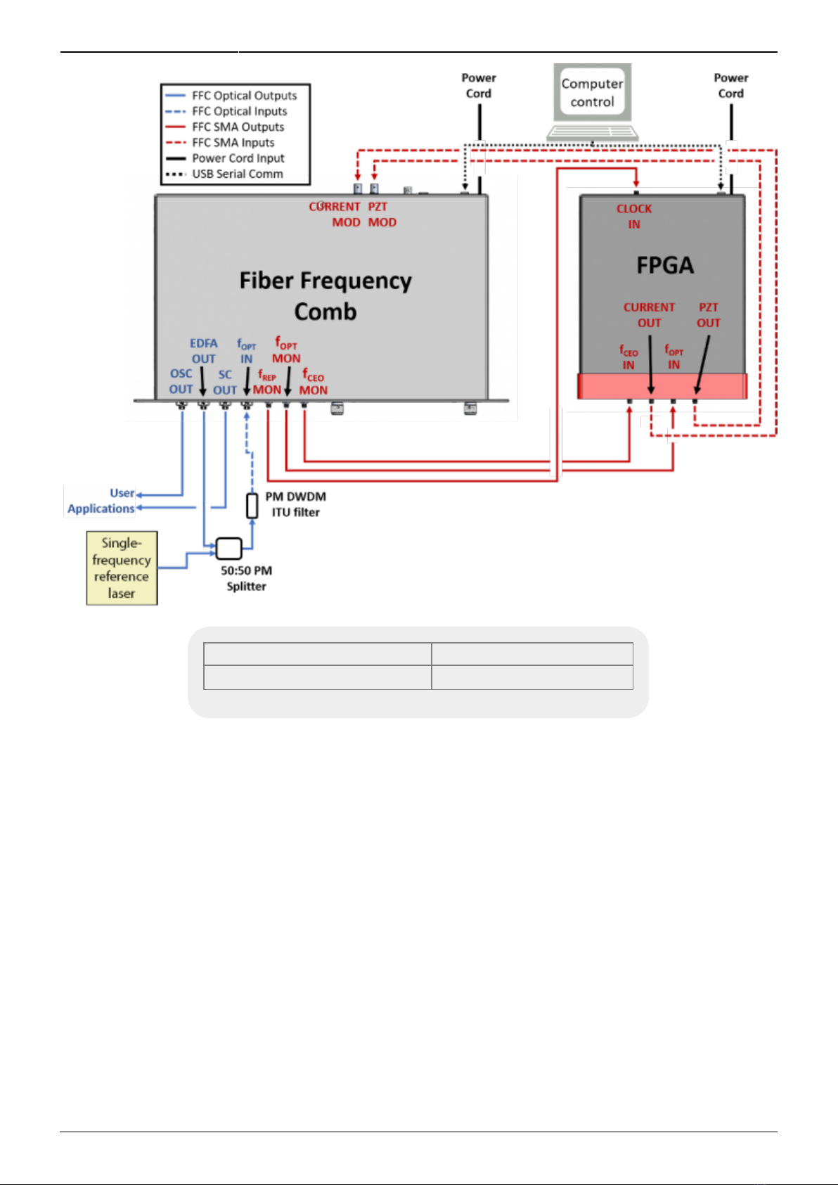
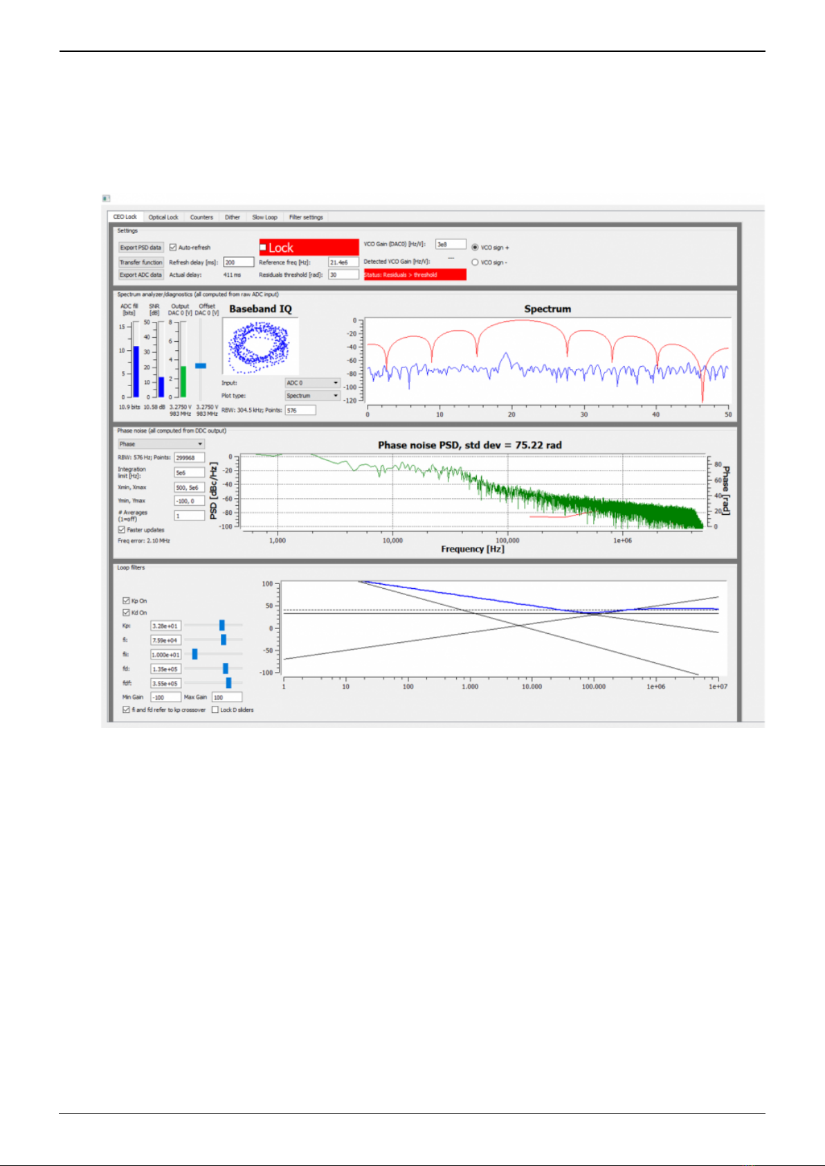
Successful implementation of the FFC-100 depends critically on the design of the
whole system: FFC-100, phase locking electronics, and any references to which the
FFC is locked or vice versa.
Initial Set-up
Download and install software according to instructions found here.1.
Ensure all cables and fibers are connected according to the connection diagram figure 2.2)
2.
Turn on the power to the Fiber Frequency Comb (FFC) and the FPGA, as well as the reference3.
laser.

2021/10/08 00:37 3/12 FFC-100 Fiber Frequency Comb Quick Start Guide
Product Manuals - https://www.vescent.com/manuals/
Fig. 2: FFC-100 electrical and optical connection diagram (Click for larger image)
Parameter Rating
ƒopt Power Input <1.5 mW max
Tab. 3: Operating Parameters
FFC-100 Operation
FFC Start Up GUI
Touch the “System Off” button at the top of the front panel screen (figure 3) to bring up a drop-1.
down menu. Select “Standby” (figure 4) to turn on temperature control of the pump diodes and
oscillator cavity.

Last update: 2021/10/06 23:13 ffc:100 https://www.vescent.com/manuals/doku.php?id=ffc:100
https://www.vescent.com/manuals/ Printed on 2021/10/08 00:37
Fig. 3: The FFC-100 GUI in off state
Fig. 4: Select Standby laser state
Once the temperature servos have stabilized and “Standby” has stopped blinking, touch the2.
“Standby” drop-down menu (figure 5) and select “Laser On” (figure 6). The FFC should
commence lasing and the Mode-locked indicator should turn green (figure 7).
Fig. 5: The FFC-100 GUI: in Standby
mode

2021/10/08 00:37 5/12 FFC-100 Fiber Frequency Comb Quick Start Guide
Product Manuals - https://www.vescent.com/manuals/
Fig. 6: The FFC-100 GUI: Standby to System On
Fig. 7: System On
If necessary, adjust oscillator current by either holding down the “Osc” touch screen button and3.
typing in a desired set-point (figure 8), or briefly pressing the button and using the two control
knobs (left changes digits, right adjusts values) to set a desired value.
Fig. 8: Adjust oscillator current via keypad
Cavity temperature can be adjusted in the same way.4.
Touch the “PZT” touch screen button (figure 9) to bring up a drop-down menu and select “Full5.
Range x20” to enable the PZT servo.

Last update: 2021/10/06 23:13 ffc:100 https://www.vescent.com/manuals/doku.php?id=ffc:100
https://www.vescent.com/manuals/ Printed on 2021/10/08 00:37
Fig. 9: Select PZT Gain
FPGA Control
The SLICE-FPGA dual-channel Offset Phase Lock Servo can be used to phase lock ƒCEO to a reference
(TBD) and ƒopt to a reference laser such as the Rio Planex.
If you have not already done so, install Python and the FPGA software for controlling the SLICE-FPGA
dual Offset Phase Lock Servo.
Software Startup
Open a WinPython command window and navigate to the folder “GUI and Firmware”.1.
Start the SLICE-FPGA control GUI by typing “python XEM_GUI3_VPv4.py”, figure 10).2.
Fig. 10: Start FPGA GUI from Terminal
A start-up menu should appear (figure 11). Make sure “superlaserland_v12.bit” is selected and3.
select an appropriate clock option. Press OK.

Last update: 2021/10/06 23:13 ffc:100 https://www.vescent.com/manuals/doku.php?id=ffc:100
https://www.vescent.com/manuals/ Printed on 2021/10/08 00:37
Locking ƒ(CEO)
Navigate to the “CEO Lock” tab and adjust the “Offset DAC 0” slider near the top left by clicking1.
and dragging the slider until the the data in the Baseband IQ plot is circular (figure 13). This
centers the beat note near the reference frequency. It is also possible to adjust the FFC-100
oscillator current on its front panel to make this adjustment.
Fig. 13: Centering ƒ(CEO) on reference frequency (Baseband IQ optimization)
Press the “Lock” button (figure 14, top middle). If the system doesn’t lock, change the VCO sign2.
to the opposite polarity (top right) and try again. If the system still won't lock, try lowering the
Kp value (bottom left).

2021/10/08 00:37 9/12 FFC-100 Fiber Frequency Comb Quick Start Guide
Product Manuals - https://www.vescent.com/manuals/
Fig. 14: Locking ƒ(CEO)
Locking ƒ(opt)
Navigate to the “Optical Lock” window. Center the beat note near the reference frequency:1.
adjust the “Offset DAC 1” slider (or your reference laser frequency) until you see a circular
Baseband IQ diagram (figure 15).

Last update: 2021/10/06 23:13 ffc:100 https://www.vescent.com/manuals/doku.php?id=ffc:100
https://www.vescent.com/manuals/ Printed on 2021/10/08 00:37
Fig. 15: Centerig ƒ(opt) on reference frequency (Baseband IQ optimization)
Press the “Lock” button (figure 16). If ƒopt doesn’t lock, change the VCO sign to the opposite2.
polarity and try again. If the system continues to not lock, lower the Kp value.\\

2021/10/08 00:37 11/12 FFC-100 Fiber Frequency Comb Quick Start Guide
Product Manuals - https://www.vescent.com/manuals/
Fig. 16: Locking ƒ(opt)
Adjust PID settings (bottom middle of figure 16) accordingly to lower the integrated phase noise3.
of each parameter (fCEO and fopt). The default settings provided in the software are a good place
to start but tweaking the values can often improve performance.
Slow Loop Feedback
Slow loop functionality will be provided in a near-term software update.
Open your computer’s device manager from the control panel and find the COM port number for1.
“STMicroelectronics”. Never assume that this number is the same as previous times. (If it
doesn’t appear, make sure your computer is connected to the FFC.)
Navigate to the “Slow Loop” tab in the GUI and enter the COM port number into “FFC COM2.
Port”.
The PZT setpoint is set to an intermediate value (50V) to keep the servo from railing. This can3.
be adjusted if desired.
Click “Activate Temperature Slow Loop”.4.
1)
Located in power receptacle on rear panel
2)
Single frequency reference laser: for instance a RIO PlanexTM 1550 nm laser.
Other manuals for FFC-100
1
This manual suits for next models
2
Table of contents
Other Vescent Industrial Equipment manuals
Popular Industrial Equipment manuals by other brands

Baker Hughes
Baker Hughes Panametrics PanaFlow LC user manual

ENOTECNICA PILLAN
ENOTECNICA PILLAN BACCO 2 instruction manual

Yoshitake
Yoshitake PG-2 product manual

Meyer
Meyer Diamond Edge 41770 Assembly instructions

Xylem
Xylem McDonnell & Miller MM-243D instruction manual

Target
Target SYSTEM TB 1000 Instruction for set up and Operation