Vescent FFC-100 User manual

2022/04/17 02:01 1/9 FFC-100 Fiber Frequency Comb Quick Start Guide
Product Manuals - https://vescent.com/manuals/
FFC-100 Fiber Frequency Comb
Model No. FFC-100-100 and FFC-100-200
Document Last Updated on 2021/08/26 14:26
Please read Limited Warranty and General Warnings and Cautions prior to operating the FFC-100.
Fig. 1: The
FFC-100 Fiber Frequency Comb
Useful Links
Vescent manuals page.
FFC-100 API.
FFC-100 web page.
Github page for FFC-100 firmware revisions
Please check back for added functionality. Contact sales [at] vescent [dot] com for questions and
corrections, or to request added functionality.
Operating the FFC
This document provides instructions on how to operate the Vescent Photonics FFC-100 when
controlled by the Vescent SLICE-FPGA.
Purchase Includes
FFC-100 rack-mountable Fiber Frequency Comb module
Power cord for your country (if known)
Instructions on how to download & install control software
Final Test Documentation
Absolute Maximum Ratings and Power Input
Note: All modules designed to be operated in a laboratory environment.

Last update: 2021/08/26 14:26 ffc:100 https://vescent.com/manuals/doku.php?id=ffc:100&rev=1605577217
https://vescent.com/manuals/ Printed on 2022/04/17 02:01
Parameter Rating
Environmental Temperature >15°C and <30°C
Environmental Humidity <60%
Environmental Dew Points <15°C
Maximum AC Line Input Current 2 A
Tab. 1: Absolute Maximum Ratings
The FFC-100 will accept input line voltages within the ranges shown in table 2.
Parameter Value Units
Input Line Voltage 100-240 VAC
Frequency 50-60 Hz
Phase 1 phase
User-serviceable fuse1) T 2.0 A L 250V
Tab. 2: Input Voltage Specifications
Proper Usage
If this instrument is used in a manner not specified by the manufacturer in this
manual or other relevant literature, protection provided by the instrument may be
impaired.
Successful implementation of the FFC-100 depends critically on the design of the
whole system: FFC-100, phase locking electronics, and any references to which the
FFC is locked or vice versa.
Initial Set-up
Download and install software according to instructions found here.1.
Ensure all cables and fibers are connected according to the connection diagram figure 2.2.
Turn on the power to the Fiber Frequency Comb (FFC) and the FPGA, as well as the reference3.
laser.

2022/04/17 02:01 3/9 FFC-100 Fiber Frequency Comb Quick Start Guide
Product Manuals - https://vescent.com/manuals/
Fig. 2: FFC-100 electrical and optical connection diagram (Click for larger image)
FFC-100 Operation
FFC Start Up GUI
Touch the “System Off” button at the top of the front panel screen (figure 3) to bring up a drop-1.
down menu. Select “Standby” (figure 4) to turn on temperature control of the pump diodes and
oscillator cavity.
Once the temperature servos have stabilized and “Standby” has stopped blinking, touch the2.
“Standby” drop-down menu (figure 5) and select “Laser On” (figure 6). The FFC should
commence lasing and the Mode-locked indicator should turn green (figure 7).
If necessary, adjust oscillator current by either holding down the “Osc” touch screen button and3.
typing in a desired set-point (figure 8), or briefly pressing the button and using the two control
knobs (left changes digits, right adjusts values) to set a desired value.
Cavity temperature can be adjusted in the same way.4.
Touch the “PZT” touch screen button (figure 9) to bring up a drop-down menu and select “Full5.
Range x20” to enable the PZT servo.

Last update: 2021/08/26 14:26 ffc:100 https://vescent.com/manuals/doku.php?id=ffc:100&rev=1605577217
https://vescent.com/manuals/ Printed on 2022/04/17 02:01
Fig. 9: Select PZT Gain
FPGA Control
Open a WinPython command window and navigate to the folder “GUI and Firmware”.1.
Execute the GUI code by typing “python XEM_GUI3_VPv4.py” (tabbing to autocomplete is useful2.
here. figure 10).
A start-up menu should appear (figure 11). Make sure “superlaserland_v12.bit” is selected and3.
select an appropriate clock option. Press OK.
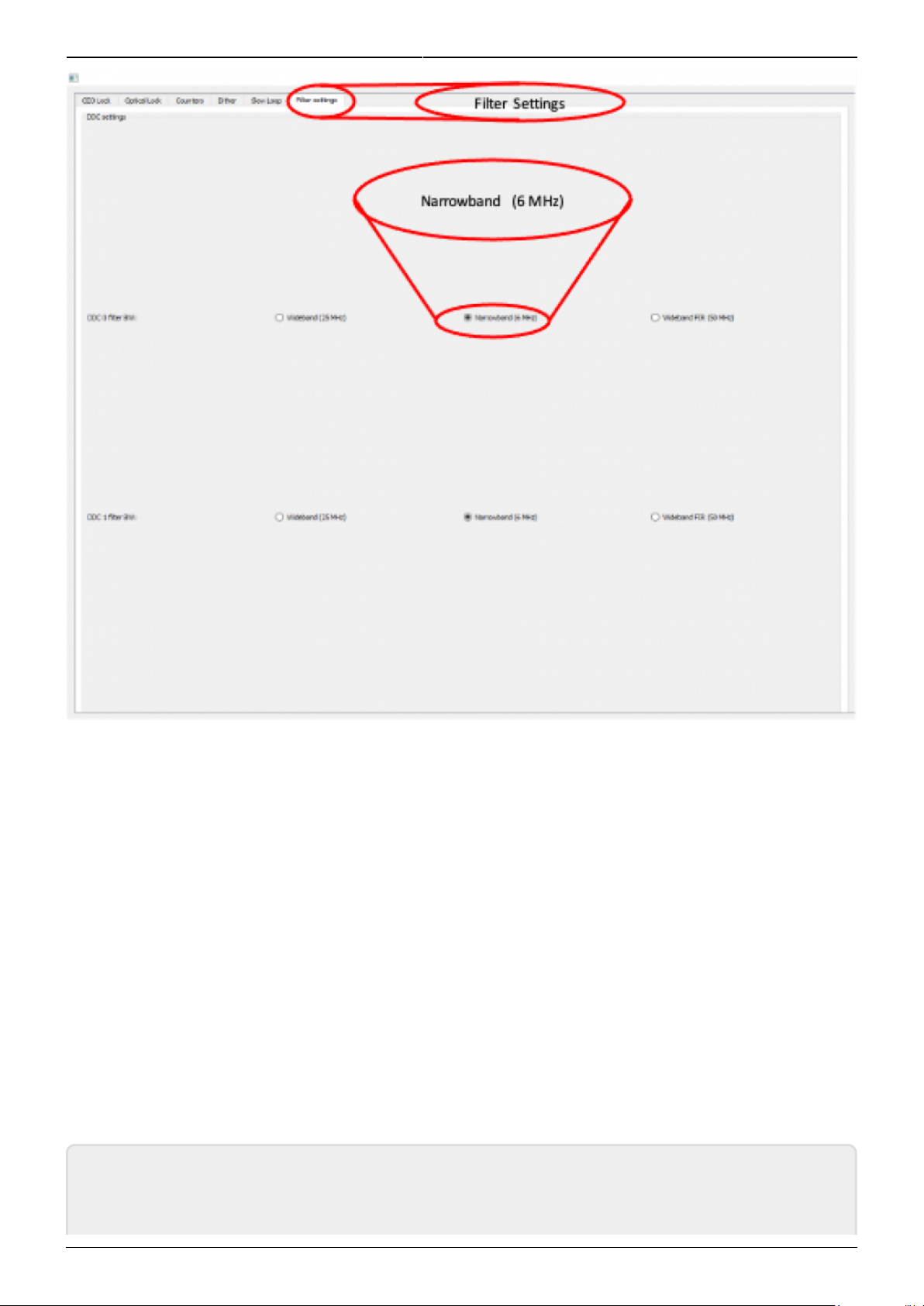
Navigate to the “Filter Settings” tab and select “Narrowband (6MHz)” for both DDC0 and DDC14.
(figure 12).
Navigate to the “CEO Lock” tab and adjust the “Offset DAC 0” slider (or oscillator current on the5.
laser’s front panel) until the Baseband IQ diagram is circular.
Press the “Lock” button. If it doesn’t lock, change the VCO sign to the opposite polarity and try6.
again. If trouble persists, try lowering the Kp value.
Navigate to the “Optical Lock” window and adjust the “Offset DAC 1” slider (or your reference7.
laser current) until you see a circular Baseband IQ diagram.
Press the “Lock” button. If it doesn’t lock, change the VCO sign to the opposite polarity and try8.
again. If trouble persists, try lowering the Kp value.
Adjust PID settings accordingly to lower the integrated phase noise of each parameter. The9.
default settings provided in the software are a good place to start but tweaking the values can
often improve performance.

2022/04/17 02:01 7/9 FFC-100 Fiber Frequency Comb Quick Start Guide
Product Manuals - https://vescent.com/manuals/
Fig. 10: Start FPGA GUI from Terminal
Fig. 11: FPGA GUI Start Screen

Last update: 2021/08/26 14:26 ffc:100 https://vescent.com/manuals/doku.php?id=ffc:100&rev=1605577217
https://vescent.com/manuals/ Printed on 2022/04/17 02:01
Fig. 12: Set Loop Filter Bandwidth
Slow Loop Feedback
Slow loop functionality will be provided in a near-term software update.
Open your computer’s device manager from the control panel and find the COM port number for1.
“STMicroelectronics”. Never assume that this number is the same as previous times. (If it
doesn’t appear, make sure your computer is connected to the FFC.)
Navigate to the “Slow Loop” tab in the GUI and enter the COM port number into “FFC COM2.
Port”.
The PZT setpoint is set to an intermediate value (50V) to keep the servo from railing. This can3.
be adjusted if desired.
Click “Activate Temperature Slow Loop”.4.
1)
Located in power receptacle on rear panel
Other manuals for FFC-100
1
Table of contents
Other Vescent Industrial Equipment manuals