Vessel Stat Buster GP-1 User manual

1
Instruction Manual
HIGH VOLTAGE POWER SUPPLY
Thank you for purchasing our Stat Buster No.GP-1.
Read this instruction manual before use. Keep it in a safe handy place for future reference.
Table of Contents
■For Your Safely ···································· P.2
■Product Overview ·································· P.3
■External View········································ P.5
■Circuit Diagram ····································· P.6
■Installation············································ P.7
■Operation············································· P.11
■MEMO ················································ P.15
■Troubleshooting & Storage ······················ P.16

2
■For Your Safely
Safety Precautions
●Carefully read these Safety Precautions before use. Observe the precautions indicated herein to
ensure safety.
●Safety precautions in this instruction manual are categorized into two types by the degree of
danger associated with each of the followings.
●If the ionizers is used in a manner not specified by the manufacturer, the protection provided by
the equipment may be impaired.
This symbol indicates a WARNING or CAUTION.
This symbol indicates a prohibited action.
This symbol indicates a mandatory required action
WARNING
PROHIBITED
Do not use in environments with flammable gases and solvents in the
atmosphere, requiring explosion-proof equipment. As this product is not
explosion-proof, there is a risk of explosion or fire.
PROHIBITED Don't use this product for other purpose than static electricity elimination.
CAUTIONS
PROHIBITED
Don't bring this product into or don't use this product in a place where
water, oil, solvent may be poured, and/or where corrosive gas such as
acid, alkali, chlorine and so on. There is a risk of electric shock and/or
product breakdown.
PROHIBITED
Don't use this product in a place where a considerable shock and/or
vibration are given, and/or where a sharp temperature fluctuation or dew
condensation occurs.
PROHIBITED
Be sure to use this product within a range of conditions of use in the
section of Specifications" including the electric rating. Otherwise, there is
a risk of fire and electric shock.
REMEMBER Installation and mainenance should be conducted by a person proficient
in electric works including wiring.
REMEMBER
If this product has broken considerably or gotten dilapidated, the electrical
noises or burning in the high voltge part (i.e. transformer) may occur.
Read this instruction manual attentively and perform a correct regular
maintenance and inspection.
WARNING Indicates that improper handling can lead to serious injury or even death.
CAUTION Indicates that improper handling can lead to minor injury and property
damage.

3
■For Your Safely
CAUTIONS
REMEMBER
This product needs to be grounded. Don't use this product without being
surely grounded. Otherwise, the product does not perform to the max
extent as designed, and a user may feel a subtle electrical shock when
he/she touches the housing.
REMEMBER
Be sure to check the product when it was exposed to considerable shock
or damage due to a drop or alike. If the product does not operate
properly and/or any abnormal operation is detected, consult us for repair
and/or replacement with a brand-new product.
REMEMBER Keep this instruction manual beside the product for a quick reference.
■Product Overview
Product Overview
This product is a compact output variable type high voltage power supply (voltage transformer) with
anomaly detection circuit, intended for supplying high voltage AC power to applicable VESSEL
ionizers, which are designed to eliminate static electricity from charged items.
This product uses 24 VDC input. Please use the dedicated AC adapter. The dedicated AC adapter
supports a wide range of input voltage from single phase 100 VAC to 240 VAC, and 50 to 60 Hz. If
using DC power supply for machinery equipment, etc., connect a 24 VDC ± 10% 1 A power supply.
In this case, connect the 0 V side to ground.
Product Features
●AC Output Voltage Adjustment Function
This power supply can adjust AC output voltage within the range of 3.5 kV to 7 kV. For this reason,
this can be used with various VESSEL ionizers.
●DC Output Voltage Adjustment Function
This power supply can output a variable DC output voltage between -150 VDC and +550 VDC on
top of the AC output voltage. The DC output is for regulating ion balance. It cannot be used as a
DC power supply. Furthermore, depending on the VESSEL ionizers connected, ion balance
adjustment may not be available.
●Safety/Anomaly Detection Circuit
This power supply incorporates a safety circuit that will automatically shut off the output when a
high voltage short circuit is detected.
●Power Indicator Light
The power indicator light employs a high-brightness blue LED with excellent visibility, so that you
can easily see whether the power is on or off from far away. This power indicator light goes out
when an anomaly is detected.
●High Voltage Output Confirmation Function
The output monitor terminals emit a voltage is 1/1000th of the high output voltage. The high
voltage output can be easily read by connecting a common digital multimeter or tester to these
monitor terminals in AC voltage measurement mode.

4
■Product Overview
Main Specifications
Unit
Model : GP-1
Usable electrodes : Our capacitive coupling type, resistance connection type, or direct
connection type of VESSEL ionizers.
Maximum load : SSB bar series with a total overall length of up to 5,000 mm
Ambient temperature
and humidity : 0 to 50℃, 10 to 90%RH (without freezing or dew condensation)
Storage temperature
and humidity : -30 to 70℃, 10 to 95%RH (without freezing or dew condensation)
Installation Location : Indoors
Rated input voltage : DC 24 V ± 10%
Rated primary current : 0.75 A or lowe
r
Output frequency : 55 ± 5 Hz (sine wave)
Variable output range
Without load (rms)
: AC output 4 kV / 5 kV / 7 kV (with internal switch,
switched/adjusted between 3 stages)
DC output -150 to +550 V (adjusted with external knob)
Factory default
settings : 6.65 kVAC ± 0.13 kV, DC 0 ± 5 V
Secondary short
circuit current : 5 mA or lower
Output monitor : 1/1000 V ± 5% of the output voltage is output to the monitor
terminals
Protection Circuit : Primary protection circuit (with fuses on the internal board)
Low-voltage detection : Anomaly detection function will operate when each output drops to
about 85% or less of the set voltage due to high voltage short
circuit or abnormal sparks.
Overcurrent detection : the anomaly detection function will operate when the output
current reaches about 4 mA or more.
Anomaly detection
sensitivity adjustment : The anomaly detection response speed can be adjusted (using
external adjustment knob)
Allowable input surge : 34 V Peak max.
Protection class : IP20
Power supply input
connector : Molex 5569-04A1-210
High voltage output
connector : Ceramic high voltage output terminal x 2
Alarm output terminal : C contact relay output
Contact rating: 125 VAC, 0.4 A or 30 V DC, 2 A (resistance load)
Switches and displays : On-off rocke
r
switches. Blue LED power indicator light (goes off
when anomaly is detected)
Material : Housing SPCC, painted white
Size : W 102.8 x D 233.5 × H 114.2 mm
Weight : Approx. 4.5 kg
Power adapter
Model : AD24-IT
Rated input : AC 100 V to 240 V (50/60 Hz), 0.4 A
Rated output : DC 24 V, 0.75 A
Ambient temperature
and humidity : 0 to 40℃/ 10 to 85% RH (without freezing or dew condensation)
Cord length : DC output cord and AC input cord, approx. 1.8 m each

5
■External View

6
■Circuit Diagram

7
■Installation
Installation Location
WARNING
PROHIBITED
Do not use in environments with flammable gases and solvents in the
atmosphere, requiring explosion-proof equipment. As this product is not
explosion-proof, there is a risk of explosion or fire.
CAUTIONS
CAUTIONS
• Take into consideration the ambient conditions surrounding the installation
location.
• Install indoors where it will be sheltered from wind and rain.
• Install in a location where it will not be exposed to water, oil or fine dust.
• Do not install in locations where considerable vibrations or shocks will
be transmitted to the unit.
• Do not bring into areas with high humidity, or where there are corrosive
gases such as acids, alkalis or chlorine gas present. Also, do not use the
product in these types of areas. There is a risk of electric shock or product
breakdown.
• Please use in areas with a temperature between 0 to 50℃, and a
humidity of 10 to 90%.
Installation work
CAUTIONS
REMEMBER
• Installation should be conducted by someone proficient in handling of
electric products, including electric wire.
• This product uses sensitive electronic circuits, so please handle it as
gently as possible and avoid subjecting it to shocks, etc.
• Do not, under any circumstances, drill holes into the unit.
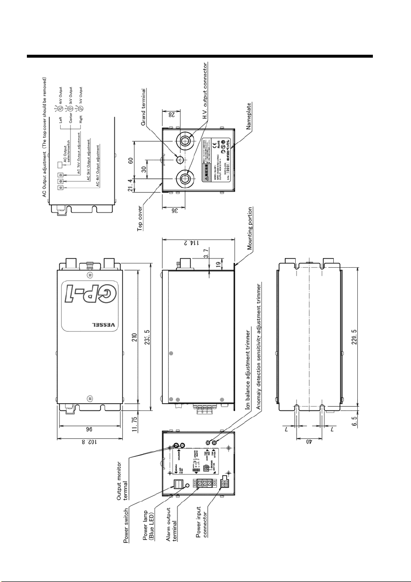
Please install the GP-1 near machinery to which load electrodes (bars, nozzles, air guns, etc.) are
connected. Secure firmly to a strong frame, wall, floor, etc. using 4 ×M5 screw through the holes in
the bottom of the mounting base. When installing the unit on a vertical surface, make sure the high
voltage output connector is downward.
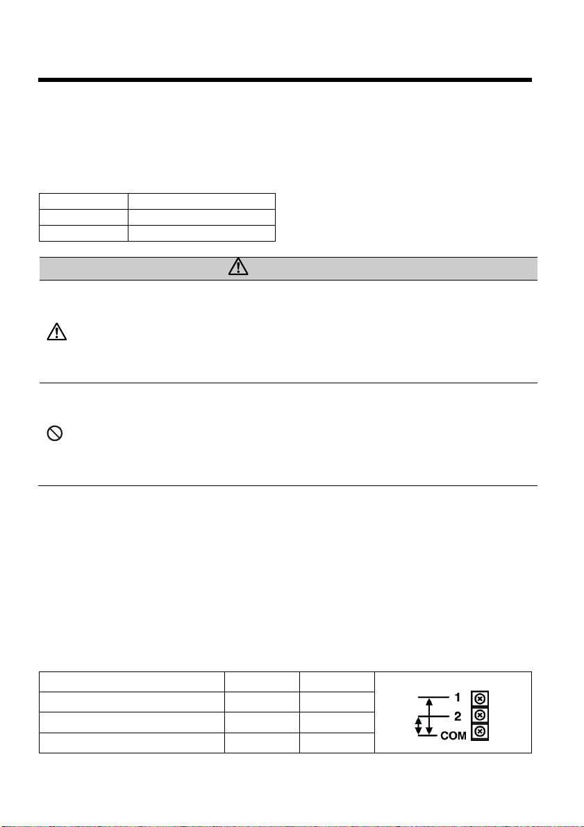
Connecting the wiring
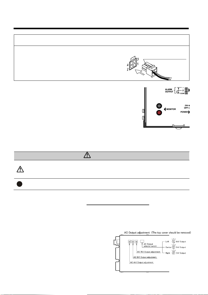
1. Be sure to connect the power adapter connector (accessory) by inserting it securely into the unit
input connector (MOLEX 5557-02R-210).
2. CONNECT THE AC CABLE TO THE POWER ADAPTER (ACCESSORY), AND BE SURE TO
PLUG THE 3-PIN TERMINAL ON THE AC CABLE INTO A 3-PIN OUTLET WITH A
CONNECTED GROUND. WHEN CONNECTING THE AC CABLE TO A 2-PIN OUTLET THAT
DOES NOT INCLUDE A CONNECTED GROUND, WIRE THE GROUND TERMINAL OF THE
UNIT TO A GROUNDED MACHINERY FRAME, ETC
* IN THIS CASE, MAKE SURE THAT THE POWER SWITCH ON THE UNIT IS IN THE OFF [○] POSITION.
CAUTIONS
CAUTIONS
This product must always be grounded. If the product is not
sufficiently grounded, it will not perform up to its full capabilities.
Also, when touching the casing you may receive a light electric
shock.

8
■Installation
When using an external power supply
Instead of using the included AC adapter, power can be
supplied externally.
Connect wiring using a MOLEX connector, as shown in the figure.
Please be sure to connect to ground. Otherwise a ground wire
may be connected to the ground terminal on the rear of the unit.
Please shut off the external power supply when stopping
operation.
Output monitor terminals
You can easily check the AC high voltage output by connecting a digital
multimeter or tester (1 MΩor more of impedance) to the output monitor
terminals (MONITOR) on the side of the unit.
(A tester pin with an outer diameter of 2 mm will fit.)
1. Put the tester, etc. in AC voltage measurement mode, and connect it to
the output monitor terminals (MONITOR). Since there is no polarity, it
doesn't matter which side you connect to the COM terminal.
2. Once the power is turned on for the unit, a value that is 1/1000th that
of the AC high voltage output (AC 4 to 7 V) will be displayed on the tester. The high voltage output
voltage will be the value which is multiplied by 1000 of the displayed value.
Ex.: If the tester shows 4.2 V, the high voltage output will be 4.2 kV
CAUTIONS
CAUTIONS
• Be sure to conduct measurements with the tester in AC voltage
measurement mode.
• Do not apply a voltage to the output monitor terminals as it may lead
to failure.
REMEMBER • Do not short the output monitor terminals or connect them to ground.
It may lead to failure.
Output voltage adjustment
Make sure to carry out output adjustment while the ionizer is disconnected. When the product has
been shipped together as a set with an ionizer, output voltage setting/adjustment has normally been
carried out already; so this procedure is not necessary.
After installation work is complete, double-check the output voltage by connecting a tester, etc. in AC
voltage measurement mode to the output monitor terminals while the antistatic electrode is
connected. Make adjustments if necessary.
AC output voltage switching
This product can switch between AC output voltages.
Remove the top cover and operate the internal selector
switch and adjustment knobs.
Output switching (AC output selector switch)
4 kV: Move to the left (position 1)
5 kV: Move to the center (position 2)
7 kV: Move to the right (position 3)
<Power supply connector>
MOLEX 5556 (pin x 2)
MOLEX 5557-04 R (housing x 1)
1. Power supply
(+24 V DC)
4. Ground

9
■Installation
AC output voltage fine-tuning
There are 3 AC output voltage adjustment knobs on the left side of the AC output selector switch. It is
possible to fine-tune the output voltage using these adjustment knobs. Make sure to operate the
adjustment knob that corresponds to the position of the AC output selector switch.
Ex.: If the switch is set to 4 kV output, operate the AC 4 kV output adjustment knob.
Output fine-tuning range (AC output adjustment knob)
AC 4 kV 3.5 to 4.2 kV
AC 5 kV 4.2 to 5.2 kV
AC 7 kV 6.0 to 7.2 kV
CAUTIONS
CAUTIONS
• Set to a suitable output voltage for each ionizer. The proper voltage for
each ionizer can be found in the instruction manual for that model.
Using the wrong voltage can lead to failure of both the unit and the
ionizer.
• Because output voltage adjustment is carried out while the unit is
energized, it is very dangerous. It should only be conducted by an
operator who has proficiency in handling of electric products, including
electric wire.
PROHIBITED
• You may open the top cover of this product in order to adjust the
adjustment knob, but do not manipulate anything other than the
aforementioned output selector switch or output adjustment knobs.
Doing so may lead to accidents or malfunction.
• The top cover is connected to the unit by a ground wire. Do not remove
or damage this ground wire.
• After making adjustments, be sure to put back the top cover. Do not use
the product without the top cover.
Anomaly Detection Circuit
For safety, the anomaly detection circuit automatically stops high voltage output when high voltage is
leaked to any part of the unit other than the electrode.
Anomaly detection external output (C-contact relay output, 3-pin terminal)
This product includes contacts for use with external alarm devices such as error lamps, buzzers, etc.
when anomalies are detected. (Because they are zero-voltage, a separate power source is
required.)
There is a few hundred millisecond delay after the power switch is turned ON before the transformer
reaches its normal value. So please include a 1 second time lag in external circuits such as PLCs.
(Please include a 1 second time lag on the PLC side after the input power source is turned ON
during which anomalies are not detected.)
Connecting terminals COM ⇔1 COM ⇔2
With power OFF Open Closed
During normal operation Closed Open
When an anomaly is detected Open Closed
Contact rated load: 125 VAC, 0.4 A or 30 VDC, 2 A (resistance load)

10
■Installation
Anomaly detection sensitivity / response speed adjustment
Anomaly detection sensitivity and response speed can be adjusted using the anomaly detection
sensitivity adjustment knob (DELAY ADJ.) on the side of the unit. Make adjustments when peripheral
noise is causing malfunction.
Adjustment knob
angle
When completely
closed
During gap
discharge
HI (full right) 40 ms or more 60 ms or more
LOW (full left) 180 ms or more 200 ms or more
* When the anomaly is due to electrical discharge, these times may change depending on
conditions.
Wiring the high voltage cable
VESSEL ionizers electrodes that can be connected to this product have either a CON-4 or CON-7
special purpose high voltage connector attached to the end of the high voltage cable. We offer
capacitive coupling type, resistance connection type, or direct connection type ionizers, and the type
of connector varies depending on the type of ionizer.
The maximum load that can be connected to this product, in the case of the SSB bar series ionizer,
is a bar with a total overall length of 5 m. Details about our other ionizers can be found in the
instruction manual for each model. Using this product with loads in excess of the maximum load
radically shortens the life of the unit, electrode, and high voltage cable. And if the load is too large,
the anomaly detection function will be activated as soon as the power is turned on, and you will not
be able to use the product.
After installing the ionizer, high voltage cable, and ground wire, firmly tighten and connect the high
voltage connector at the end of the high voltage cable to the ceramic output terminals on the unit
(there are 2) by hand. (Do not use tools such as pliers.) If the high voltage cable is shielded, be sure
to connect the ground wire on the end of the cable, to the ground terminal on the unit.
* For precautions on connecting the high voltage cable, please read the instruction manual for the
corresponding ionizer.

11
■Operation
Operation
When the power switch (POWER) is moved to the [ I] position, the power indicator light glows blue
and operation begins.
〇Power indicator light comes on
〇Error alarm output contacts (C-contact relay output) operate, and the display is normal.
□If a tester, etc. is connected to the high voltage output monitor terminals, the unit output
voltage will be shown on the tester. (The value shown on the tester is 1/1000th of the AC
voltage.)
〇High voltage is fed through the high voltage cable to the ionizer and static elimination begins.
Halting operation
When the power switch (POWER) is moved to the [〇] position, the power indicator light goes out
and operation stops.
〇Power indicator light goes out.
〇Error alarm output contacts (C-contact relay output) cease to operate.
□The tester, etc. shows approximately 0 V.
〇High voltage output is stopped, and static elimination ceases.
Anomaly detection
If sparks occur, or if there is a high voltage short-circuit, etc., resulting from an anomaly in the high
voltage cable, electrode, or power transformer, high voltage output will be turned OFF and the power
indicator light will go out.
〇Power indicator light goes out.
〇Error alarm output contacts (C-contact relay output) will switch to an error display.
□The tester, etc. shows approximately 0 V.
〇Static elimination ceases.
* Be sure to turn the power switch [OFF], then remedy the cause of the anomaly.
Resetting
After the cause of the anomaly is determined, and the anomalous state eliminated through repair or
replacement, turn the power switch [ON].
〇Returns to operational status.
* If the anomalous state has not been eliminated, it will once again change to an error display.
CAUTION
REMEMBER • When the product will not be used for an extended period of time, unplug
the AC cable from the outlet.

12
■Operation
CAUTION
CAUTION
• Malfunctions may occur due to electrical noise during momentary power
failures, lightning strikes, high-capacity motor startup, etc. If the product
shuts down abnormally for one of these reasons, perform a reset. If this
occurs frequently, use the anomaly detection sensitivity adjustment (P.10)
to set the sensitivity to LOW.
• When performing a reset using the power switch, once you have turned
the power OFF, wait 10 seconds or more before turning it ON again.
• If the power is repeatedly turned ON and OFF in short cycles, a load will
be placed on the internal transformer, etc. and shorten the life of the
device. Try to leave 5 minutes or more for each continuous recurring cycle
between ON and OFF.
Ion balance adjustment
This product can enables to adjust ion balance.
If the balance of positive and negative ions produced by the electrode is off, the static electricity
cannot be removed, or instead, it is produced. This product can output DC voltage in addition to the
AC high voltage output. By manipulating this DC voltage, the ion balance can be adjusted.
There is an adjustment knob on the other side of the connectors.
Turning the knob labeled (ION BALANCE ADJ) to the left or right
increases or decreases the DC voltage, adjusting the amount of
positive and negative ions produced by the ionizer.
Carry out adjustments by measuring the actual ion balance with
a CPM (charged plate monitor) etc.
IF THE PRODUCT HAS BEEN PURCHASED AS A SET WITH AN IONIZER, THE ION BALANCE
HAS BEEN ADJUSTED BEFOREHAND BASED ON PRE-DETERMINED STANDARD USAGE
CONDITIONS. BECAUSE THE ION BALANCE WILL VARY DEPENDING ON INSTALLATION
DISTANCE, USE OF COMPRESSED AIR, ETC., IT IS RECOMMENDED TO PERFORM ION
BALANCE ADJUSTMENT BASED ON ACTUAL USAGE CONDITIONS.
CAUTION
CAUTION
• If the ion balance is an important factor in the location where this product is
used, use with just 1 ionizer connected to the unit. The ion balance cannot
be individually adjusted for each ionizer when multiple models are
connected to the same power supply unit. For example, if 2 ionizers are
connect to the same unit, and the ion balance is adjusted for one of the,
ionizers the ion balance of the other ionizer may not be as expected.
• Ion balance adjustment cannot be carried out for "SSB bar series".
For other ionizers, please consult the instruction manual for each model.

13
■Procedures in Abnormal Conditions
Sparks from the electrode needles
There should be no visible sparks from the static elimination device system during normal use. If you
see these kinds of sparks continuing to occur at the electrode needles, etc., make sure to perform
necessary maintenance such as cleaning them. If cleaning does not exclude the occurrence of
sparks, stop the supply of power to the unit and contact the dealer from which the product was
purchased.
Other anomalies
If any of the following phenomena occur, immediately stop the supply of power to the unit and
contact the dealer from which the product was purchased.
• Sparks are being emitted from the ionizer, part of the high voltage cable, etc.
• The unit output connector, or part of the high voltage cable has melted.
It is smoking or burning.
• A strange smell is coming from the unit.
• The unit is considerably distorted.
• The unit is abnormally hot. (enough that it cannot be touched with bare hands)
• It is making an unusual humming sound. (which can be easily heard from 1 maway)
• The power indicator light does not come on even though the power switch is turned to ON.
CAUTION
PROHIBITED
Do not use the product in the following conditions. Risk of fire or
electric shock.
• The product is broken due to dropping or shock.
• The power indicator light does not come on even though the power
switch is turned to ON.
• The cord is damaged or heated up.
• The plug to the connector or outlet is loose.
UNPLUG
POWER CABLE
When any abnormal condition is detected, turn off the power switch
and pull out the power supply connector.
DO NOT
DISASSEMBLE Never disassemble the product.
Continuously using the product during failure or abnormal conditions may lead to product
breakdowns or accidents, so please request repairs in a timely manner. Contact the dealer from
which the product was purchased for repairs.

14
■Procedures in Abnormal Conditions
Troubleshooting
Phenomenon Cause Measure
Power indicator light
does not come on.
The correct input voltage is
not being supplied.
Check the output voltage or polarity of
the AC adapter or DC power supply.
Sparks are emitted from
the electrode needles
when the power is
turned ON.
The appropriate output
voltage is not being used.
Switch to the appropriate voltage
shown in the instruction manual of
the ionize
r
.
The output voltage is high
due to heavy load.
Adjust the output voltage. Or else
decrease the load. (Reduce the
number of ionizers, or shorten the
length of the high voltage cable.
The output voltage value
cannot be measured
correctly.
The input impedance of the
connected tester, etc. is low.
Use a tester, etc. with an input
impedance of 1 MΩor more.
The output voltage
cannot be adjusted.
You did not turn the adjustment
knob that corresponds to the
set voltage.
Each set voltage of 4 kV, 5 kV or 7
kV has a different adjustment knob.
The adjustment knob is
broken.
Request repair.
Ion balance adjustment
cannot be carried out.
You are using a capacitive
coupling type electrode.
Ion balance adjustment cannot be
carried out for capacitive coupling
type antistatic electrode.
The anomaly detection
circuit operates and
stops output.
Bad ground. Inspect each ground.
The load is too great. Decrease the load. (Reduce the
number of electrodes, or shorten the
length of the high voltage cable.
The electrode and insulation
of the ionizer are extremely
dirty.
Clean or replace the electrode
needles, etc.
Failure of the electrode or
high voltage cable (short
circuit, etc.).
If the anomaly detection function
does not execute when the electrode
or high voltage cable is removed
from the unit, replace the electrode
or high voltage cable.
Failure of the unit. If the anomaly detection function
executes when the electrode or high
voltage cable is removed from the
unit, repair or replace the unit.
■Storage
CAUTION
PROHIBITED
Do not store the product in the following locations. There is a risk of product
breakdown.
• Where considerable vibration or shock is transmitted to the unit
• Areas with heat, humidity or condensation exceeding the range shown in
the specifications
• Areas where an abrupt temperature change occurs
• Areas where there is a risk of ignition or explosion such as near flammable
solvent or dust powder
• Areas with a lot of dust and smoke, or where water, oil, or chemicals may
be poured on the product
• Areas where an intensive electric field or ferromagnetic field is generated

15
■MEMO

16
LIMITED WARRANTY:
VESSEL expressly warrants that for a period of one (1) year from the date of purchase, VESSEL
static erasers will be free of defects in material (parts) and workmanship (labour). Within the
warranty period, Defects occurring will be repaired or products will be replaced at VESSEL's option
and expense, if VESSEL receives notice during the warranty period. Defective products must be
returned to VESSEL Osaka Japan with proof of purchase date. And if your unit is out of warranty,
VESSEL will quote repair charges necessary to ship your unit freight prepaid to where you have
originally purchased.
WARRANTY EXCLUSIONS:
THE FOREGOING EXPRESS WARRANTY IS MADE IN LIEU OF ALL OTHER PRODUCT
WARRANTIES, EXPRESSED AND IMPLIED, INCLUDING FITNESS AND MERCHANTABILITY
AND FITNESS FOR A PARTICULAR PURPOSE WHICH ARE SPECIFICALLY DISCLAIMED.
The express warranty will not apply to defects or damage due to accidents, neglect, misuse,
alterations, operator error, or failure to properly maintain, clean, or repair products.
LIMIT OF LIABILITY:
This electronic static eraser use high voltage corona discharge and should not be used in or near
flammable or explosive environments. In no event will VESSEL or any seller is responsible or liable
for any injury, loss or damage, direct or consequential, whether based in tort or contract arising out
of the use of or the inability to use the product. Fulfillment of VESSEL's warranty obligations will be
Customer's exclusive remedy and VESSEL's and Seller's limit of liability for any breach of warranty
or otherwise. Before using this unit, users shall determine the suitability of the product for their
intended use, and users assume all risk and liability whatsoever in connection therewith.
Model GP-1
Warranty (1) year from the date of purchase
Customer Name
Address
Tel. No.
Dealer Name/Address/Tel. No.
Manufactured by:
17-25, Fukae-Kita 2-chome,
Higashinari-ku, Osaka 537-0001 Japan
Tel : +81 6 6976 7778 Fax : +81 6 6972 9441
URL : http://www.vessel.jp
MADE IN JAPAN
16120000.00000
Table of contents
Other Vessel Power Supply manuals
Popular Power Supply manuals by other brands

Zeta Alarm Systems
Zeta Alarm Systems SSG1 instruction manual

Cisco
Cisco 2500 Series Installing guide

Carlisle
Carlisle Ransburg 78789 Service manual

Pulsar
Pulsar PSUPS20A12CR manual

Warner Electric
Warner Electric CBCx-001 Installation & operation manual

FiveFish Studios
FiveFish Studios PSU-2448mk2 Assembly guide