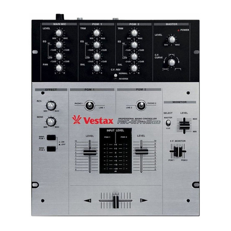
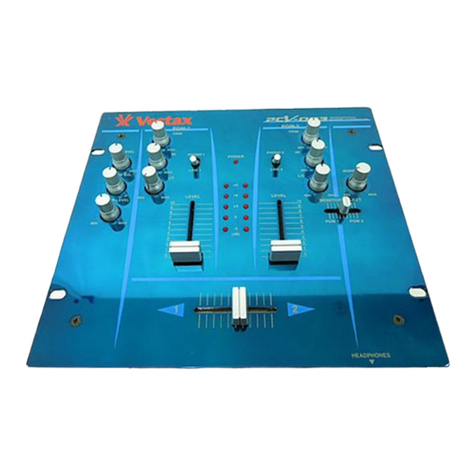
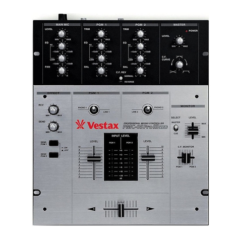
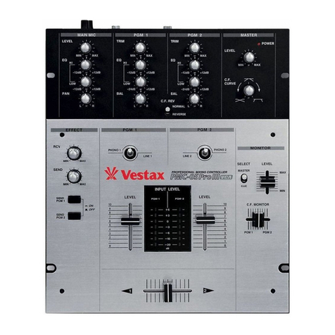
Vestax PMC-05 Pro III VCA User manual

Vtrcstax
Professionol Mixing Controller
ω脚
』り
「
OWNER■ S MANUAL
Vestax Corporation
l‐ 18・ 6 Wakabayas‖ ,Sebgaya・ ku,Tokyo 154・ 0023 Japan
Phone 03‐ 3412‐ 701l Fax 03・ 3412‐ 7013
Web:www.vestax.com
Vestax(Europe)Ltd.
Un1 5 Riverwey lndustria:Park Alton Hampshire GU34 20L Eng:and,UK
phone(0)1420・ 83000 Fax(0)1420‐ 80040
Web:www,veetax.co.uk
Vestax Europe Technical SuppOrt
Rheinstr.213D・ 53332 Bornheim Germany
phone 49(0)2222・95・ 23・ 72 Fax 49(0)2222・ 95・ 23・ 74

CONGRATULATIONSノ
Thank you for your purchasing the VESTAX PMC-05ProlllVCA, Professional Mixing Controller. We
suggest that you read through this owner's manual thoroughly so that you may enjoy the full use
of this product safely and in the knowledge of all its special features and suitable applications.
⊂ONttENttS
CAUT:ON
IMPORTANTSAFEGUARDS
F E AttU R E S
FUNC丁 10N
丁
OP PANEL
FRONT PANEL
REAR PANEL
HOVVTOCHANGETHEFAD[RUNIT
CONNECT:ON
SPEC:FiCAT10NS
2
3
4
5
5
7
7
8
10
11
CAUT10N:丁 O REDUCE THE RISK OF ELECTRIC
DO NOtt REMOVE COVER(OR BACK)
NO USER― SERVICEABLE PARTS INSIDE
△
一
SH
OCK
REFER SERV:CiNG TO QUAL:F:ED SERViCE PERSONNEL
The lichtning flash n'ith arrcnvfead symbol, within an equilateralt riangle, is intended to
alert the user to the presence of uninsu.lated "dan€;erous voltage" within the product's
enclmtre that mo. be of sufficient maenitude to consitute a risk of electric shck to perscns.
The exclamdion pcint within an equilateral trian€lle is intended to alert the user to the presence
of impcrtant cperating and maintenance (servicing) instructicns in the literature acccrnpn:,'in€:
the appliance.
丁
O REDUCE ttHE RISK OF FIRtt OR ELECTRIC SHOCK, DO NOT
圧
XPOSE ttHIS APPLIAN CE TO RAIN OR MOIST∪ RE.

lMPORTANT SAFEGUARDS
READ BEFORE OPERATING EQUIPMENT
This product was designed and manufactured to meet
strict quality and safety standards. There are, however,
some installation and operation precautions which you
should be particularly aware of.
1. Read instructions-All the safety and operating
instructions should be read before the appliance
is operated.
2. Retain instructions-The safety and operating
instructions should be retained for future
reference.
3. Heed Warnings-All warnings on the appliance
and in the operating instructions should be
adhered to.
4. Follow Instructions-All operating and use
instructions should be followed.
5. Cleaning-Do not use liquid cleaners or aerosol
cleaners. Use a damp cloth for cleaning.
6. Attachments-Do not use attachments not
recommended by the product manufacturer as
they may cause hazards.
7. Water and Moisture-Do not use this product near
water-for example, near a dath tub, wash bowl,
kitchen sink, or laundry tub, in a wet basement,
or near a swimming pool, and the like.
8. Accessories-Do not place this product on an
unstable cart, stand, tripod, or table. The product
may fall, causing serious injury to a child or
adult, and serious damage to the appliance. Use
only with a cart,. stand, tripod, bracket, or table
recommended by the manufacturer, or sold with
product. Any mounting of the appliance should
follow the manufacturer's instructions, and
sholud use a mounting accessory recommended
by the manufacturer.
9. This product should never be placed near or over
a radiator or heat register. This product should
not be placed in a built-in installation such as a
bookcase or rack unless proper ventilation is
provided or the manufacturer's instructions have
been adhered to.
10. Power sources-This product should be operated
only from the type of power source indicated on
the marking label. If you are not sure of the type
of power supply to your home, consult your
appliance dealer or local power company.
11. Lightning-For added protection for this product
during lightning storm, or when it is left
unattended and unused for long periods of time,
unplug it from the wall outlet. This will prevent
damage to the product due to lightning and
power-line surges.
12. Overloading-Do not overload wall outlets and
extension cords as this can result in a risk offire
or electric shock.
13. Object and Liquid Entry-Never push objects of
any kind into this product through openings as
they may touch dangerous voltage points or
short-out parts that could result in a fire or
electric shock. Never spill liquid of any kind on
the product.
14. Servicing-Do not attempt to service product
yourself as opening or removing covers may
expqse you to dangerrous voltage or other
hazards. Refer all servicing to qualified
sersonnel.
15. Damage Requiring Service-Unplug this product
from the wall outlet and refer servicing to
qualified service personnel under the following
conditions:
a. When the power-supply cord or plug is
damaged.
b. Ifliquid has been spilled or objects have fallen
into the product.
c. If the product has been exposed to rain or
water.
d. If the product does not operate normally by
following the operating instructions. Adjust
only those controls that are coverd by the
operating instructions as an improper
adjustment of other, controls may result in
damage and will often require extensive work
by a qualified technician to restore the product
to its normal operation.
e. Ifthe product has been dropped or cabinet has
been damaged.
f. When the product exhibits a distinct change in
perfromance-this indicates need for service.
3
16. Replacement Parts-When replacement parts are
required, be sure the service technician has used
replacement parts specified by the manufacturer
or have the same characterristics as the original
parts. Unauthorized substitutions may result in
fire, electric shock or other hazards.
17. Safety Check-Upon completion of any service or
repairs to product, ask the service technician to
perfrom sefety checks to determine that the
product is in proper operating condition.
18. Carts and Stands-The appliance should be used
only with a cart stand that is recommended by
manufacturer.
19. An appliance and cart combination should be
moved with care. Quick stops, excessive force,
and uneven surfaces may cause the appliance
and cart combination to overturn.
ⅣfW FFArtJRE5&FEATIJRE5丁HAtt yf5丁ハχ RλDE57ハⅣDARD
NEW
' Effects routing. I x Effects Send and I x Effects
Receive means that you can hook up an external
effects unit for use during play. The volume of
your send and receive signal is easily controlled
tlrough 2 x volume knobs and the signal can be sent
to PGMl, PGM2 orboth simultaneously.
'New PCV Cross Fader. The new PMC{SProlllVCA
comes standard with Vestax's latest proprietary
cross fader. Extra smooth, fast and amazingly
precise, this plastic conductive volume fader is
built to last and survive the most intense play
possible.
' New Input Switch. Designed for rugged and fast use,
this new input switch will stand up to just about any
punishment and is designed to allow quick and
constant changing between phono and line inputs. It
is also omni positional meaning that you can have it
set to its standard position or a number of angles it
for easy use.
' New Look. The new PMC{SProlllVCA has not only
undergone a technology upgrade but it also sports a
new look with a new set of rotary knobs. These new
knobs are built to reduce slippage and improve
fast access at all times.
' Monitor Cue. Select between monitoring the cue
signal or the master signal. Great for practice and
live play.
' Improved EQ specifications. The EQ section on the
PMC-OSProlllVCA has an improved frequency
response of -26d8 to +6dB.
FEATURES THAT VESTAX MADE STANDARD
' Double Panel. Vestax invented the double panel
system in order to open up the faceplate for fast
moves and reduce personal injury (fingernails).
This full battle worthy layout was designed with a
lot of advice from top-level scratch and
performance DJs and has become the layout
standard for scratch and performance mixers
since.
'User Replaceable Parts. It is a given that you
will punish your mixer enough to need to replace the
cross fader, an input fader and possibly the input
select switch. Thus, Vestax came up with the
concept ofuser replaceable parts. You can easily
replace and or upgrade the faders and the input
switches on the PMC-05Pro series by yourself in
just a few minutes.
' Cross Fader Curve Control. Vestax faders have
an undeniably great feel about them. They are
smooth, responsive and strong enough to
withstand most punishment. But making them
even more performance friendly is that the curve of
the fader can be preset or adjusted to suit your
playing style.
4

Fυ Ⅳ
C丁′
ON5
70PIP費ⅣFl
PGM 2
BAL
11●EFFECT
①
│1111:菫 =│■ 111静麟瀬降
二
籍il1111
RCV
◎
│● ■
■■
麟金腱1"On■ ■■
囀LEVEL
紘
vestax魃颯
貶盪
LEVEL LEVEL
]貫 器9 1= ■ ´CFMON:TOR
■
一lliギヤ燎薔│ │
END
¨■ 8
│1疇冶
雫早││
2 1=
1 ■
。
■
◎││││ │││ ◎
││ ││││
5

①MAIN MIC LEVEL
AttustS the inputlevel ofthe MAIN MIC input.
②MiC EQs
AttustS the HI and LOⅥ /frcquencies for bOth thc
MAIN and SUBヽ41C input.
③
M:C PAN
AttustS the panning for both the MAIN and SUB
MIC
④
TttM(PCM1/PCM2)
AttustS the input level of cach channel For optimal
acoustic quality,setthe INPUT FADER to a position
of 7 or 8 then attust tlle TRIM so that a sufflcient
signalis fcd through thc channel、 vithout distorting.
C)PCM EQs(PCM1/PCM2)
AttustS thC HI and LOW frequcncies for cach PGM
channcl.
⑥
PCM BALANCE(PCM1/PCM2)
AdiustS the stereo balance for each PGM Channel.
Call also be used to attuSt an l■ lbalanced sterco image.
F■ oln a center position a clockwise rotation will
increase thc volumc of channel R ovcr L. `
西■ereas,a
Countcr clockwise rotation will increase thc volumc of
chamcl L ovcr R.
⑦CROSSFADER REVERSE SW:TCH
Reverses thc action of the crossfadcr by switching
PGMl and 2. Rcvcrsc mode,、 vhen on,is indicated
in the LED section.
③
MASTER LEVEL VOLUME
A●■lstS thC Signallevel outputS tOlm LIblE OUT.
⑨
CROSSFADER CURVE
AttustS the crossfader curve.A clockwise rotation
gives a stccp crossfadcr good for scratching and
cutting,、 vhereas,a counter clock、vise rotation gives a
gentlc crossfader good for long running lrnixes.
⑩POWER LED
Lights up when thc POWER SWITCH is on.
①
lNPUT SELECT OR
Used to selcct lle mutlLX or PHONO)to bC Sent to cach
PGNI chamlcl.Thc upp∝ mclstposhon宙 I sclcct PHONO lput.
This selcctor switch can also be used to perお rm for
■UNSFORNIIER SCRATCH The operation direction of tts
swltch islectable To claBe t騰 opcratlollal dircctt of tl■ s
輛
血rclnclvetttoppanelandmake ttneceurytttoppanel.
⑫
lNPUT FADER(PCM1/PCM2)
Uscdto adiuSttlle iputlevcl ofcachPGM dMШ に
1.The hput
fader cune can bc changed using a s、 vitch located on thc unit
itsell This量 b is a user replaceable umt.Ensure that you
replace with an IF‑05PCV when itis woln out.For more
comprehensive instructions please refer to the nHour To
CHANGE■E FADERIJu"s∝血Ofthis uscr〔 ⅢdC・
⑬lNPUT LEVEL METER
Thc LED level lneters indicate thc signal level of each
FADER POSi丁10N
PGNI channel.
①CROSSFADER
恥
「
hen the input levels of PGⅣ ll and PGN12 are properly
set,PGMl will bc heard with the crossfadcr sct to the lcn
side,PGⅣ12 will be heard with the cross fadcr sct to the
right sidc.When the crossね der is sct in the center,both
programs win be hcard. This is user rcplaccablc fader
Replace with a HCF‐ PCV"when itis wom out.
⑮
EFFECT RCV LEVEL
AttustS the signal lcvcl input from an cxtcmal effects unit
conncctcd to the EFFECT RCVjacks on thc frontpanel.
⑩
EFFECT SEND LEVEL
AttustS the signal level output tO an extemal cffccts
unit connccted to thc EFFECT SEND JACK on thc
rear pancl.
①
EFFECT SEND ON/OFF SWITCH
This switch is used to select the PGM to bc sent to
EFFECT SEND JACK.
⑬
MON「OR LEVEL
AttustS the headphone mOnitorlevel.
⑩
CF MONttOR
Crossfadcrs signalto bc monitored frOm cach program.
⑩
MON:TOR SELECT SWiTCH
This switch is used to select the signal sent to the monitor
section ヽVhcn set to CUE the signal heard is detcnnined
:I騰流∬庶
:littυ 鵠
∬:鳳謡胤
旨
;‖
will hear the master signal in the monitor sectio■ .
LE V E L

④
PHONE JACK
Conncct thc headphoncs with the impedance of
8ohm to 600ohm.
④
EFFECT RECEⅣ E JACK
Connect to the output ofthe extemal cffccts.
REAR RANFl
FROⅣ
「PAⅣF二
④
SUB MiC LEVEL
AdiustSthe inputlevel from SUB MIC IN
④
MAIN/SUB MiC JACK
Inputjack for MAN/SUB MIC.
④
‖
NEINPUT JACK
These jacks are used to connect line level output
devices to the PMC‑05ProⅢ VCA. Devices with a line
level of‑10dB to Odb,such as CD player,MD
players, tape decks, DAT players ctc. may be
connected to these jacks.The signal from thcse
devices is then fed to the respcctive PGM、 vhen Line
lnput is selected.
④PHONO:NPUT JACK
These jacks are used to connect tumtables equippcd
with moving magnct(MM)type cartridges.Once
G)EFFECT SEND JACK
Connectto the input ofthe cxtcmal effccts.
(Delay,Rcvcrb etc)
connectcd,the signal from thc turntablc is fcd to the
respectivc PGM whcn thc Phono lnputis sclccted.
④GROUND TERM:NAL
Conncct this tcrlninal to the ground lead of the
turntables.
④
POWER JACK
Conncctthe Vcstax A⊂ ‑14′ AC adaptor.
⑩
LINE OUT
Thc PMC‑05Pro‖ VCA has two pairs of Line Outjacks
sending the same output signal to an cxternal
ampliflcation dcvice. Connect your powcr amplifler
or other likc ampliflc誠 lon de宙cc to thcscjacks
①
POWER SWttCH
Useto tum power on.
7

″
101WIIF10.C″ ハⅣ
ICr17‖r.:「ハ
IDfR υ
″
′7
①Rcmovc mc Ldcrknobs.(ScC ig―a)
②Rcmovethc 4 screws which ix thetop panel.
(SCe flg― →
③Remove the 2 screws whch ix theねder pand,and
removc the fadcr unit frOm position in mixer.
(See flg¨ b)
④ Carefully remOve the multi― cable connector iom the
fader unit.
⑤Rcmovethcね dcr knob ofnewねdcr u血 t.
⑥Attach muhi― cabL collnector to newね der un■ .
(SCe flg‐ c/d)
⑦PosHon the newね dcr lln■ careiny and secure wiぬ
screws.
fig¨ afig‐ b
MA:N PANEL
fig‐ cfigttd
Set switch to mPMc"pOsition
CROSSFADER UN「 〔
CF―PCV〕
ER □ A
V
RD
O
R
IIIIII
Ψ
=
U
9
ф
︲
R EV
RD
○
爾 Ψ U
貝 ︶
ロハ ︲
8
…
INPUttFADER UN「F〔 IF― E15PCV〕

│″01И′
1701CHA″C』:rNPυlrlsrtFc71SIИ ttTCH
①Removcthc top pand in the samc procedllc.
(See ig― →
②Rcmtte■e2scКws軸iCh瞭 the swith panel,■ x■e
switch panel, and removc the su/itch unit from
position in mixer.(Scc flg― c)
③Caremlly rcmove thc multi‐ cttle cOllnector iom the
switch unit.(See flg― う
④Attach multi― cable conncctor to new switch unit.
⑤
Position the switch unit caremlけ ,and secure with
scre、vs.
‐
″01爾‐
‐
‐
70κ調囃
1霧ICFFHFlarREc爾 01″ rIP″TlsFlrCTlsl″7TCH
①Remove thc top panelin thc same proccdure.
(See flg― a)
②Remove the 2 scrcws which ix the swhchpanel,and
rcmovc the s、 vitch unit from position in mixer.
(See flg― c)
fig¨e O
③ChangC the direction,and securc with screws.
④Replace thc top panel and secure with screws.
Fig口 f
¨○ ○○
remove the multi‐cable
connector
→
h
9

CONヽど
CrrOⅣ
TURN TABLE[VESTAX PDX‐ 2000]
ド 呻 ︱ ︱ ︱ ︱ ︱ ︱ ︱ ︱ I A
﹁
Ψ
I
I
I
I
I
I
I
I
ム
詭
﹈
POWER AMP
[VESTAX DA― X1000]
SPE
AKER
TURN TABLE[VESTAX PDX‑2000]
10

SPFCrFJ TJOⅣ
NOMINALiNPUT LEVEL lMPEDANCE
lNPUT
SECT10N
MIC ‐
54dBv 3.3kΩ
LiNE ‐
10dBv 10kΩ
PHONO 口
42dBv 40kΩ
RCV ‐
10dBv 10kΩ
NOMINAL OUTPUT LEVEL lMPEDANCE
LINE ‐
10dBv 2kΩ
υUIPUT
SEC丁:ON PHONES 58mW MAX(047Ω )≧8Ω
SEND ‐
10dBv 2kΩ
FREQUENCY RESPONSE 25Hz〜25kHz
CROSS TALK ≧100dB
SN RAT10 ≧75dB
THD <0.01%
D:MENS10N(W× H× D) 103αv)× 320(H)× 262(D)rnm
WE:GHT 3.5kg
11

JAN.2005 PMC¨ 05Pro‖ lE①
P/N:4301‐ 7103‐2
Vesttt Corporation
Table of contents
Other Vestax Controllers manuals

Vestax
Vestax VCI-100MKII User manual

Vestax
Vestax VMC-185XL Quick start guide

Vestax
Vestax PMC-06Pro T User manual

Vestax
Vestax PMC-05ProIII User manual

Vestax
Vestax PCV-002 User manual

Vestax
Vestax PMC-007 User manual

Vestax
Vestax VMC-004 User manual

Vestax
Vestax PMC 500 User manual

Vestax
Vestax VMC-002 User manual

Vestax
Vestax PMC-05PRO3VCA User manual

Vestax
Vestax PMC-06Pro VCA User manual

Vestax
Vestax VMC-004FX User manual

Vestax
Vestax VCI-100 User manual

Vestax
Vestax VMC-004FXu User manual

Vestax
Vestax PMC-05ProIII User manual

Vestax
Vestax VMC-002 User manual

Vestax
Vestax PMC-280 User manual

Vestax
Vestax PMC-05Pro User manual

Vestax
Vestax PMC-580Pro User manual

Vestax
Vestax VCM-600 User manual