EKKO EB18E User manual

The Specification
EB18E/ EB20E Serial Full Powered Walkie Stacker
Note: Before using must read this manual and the various warning label!
EKKO
Material
Handling
Equipment
Manufacturing,
Inc

1
Contents
1.The eneral Introduction..........................................................................................................................2
2.Proper usage................................................................................................................................................ 2
Modification............................................................................................................................................... 3
3.Introduction of the product...................................................................................................................... 3
3.1 Model Overview...................................................................................................................................4
3.2 Model.................................................................................................................................................... 4
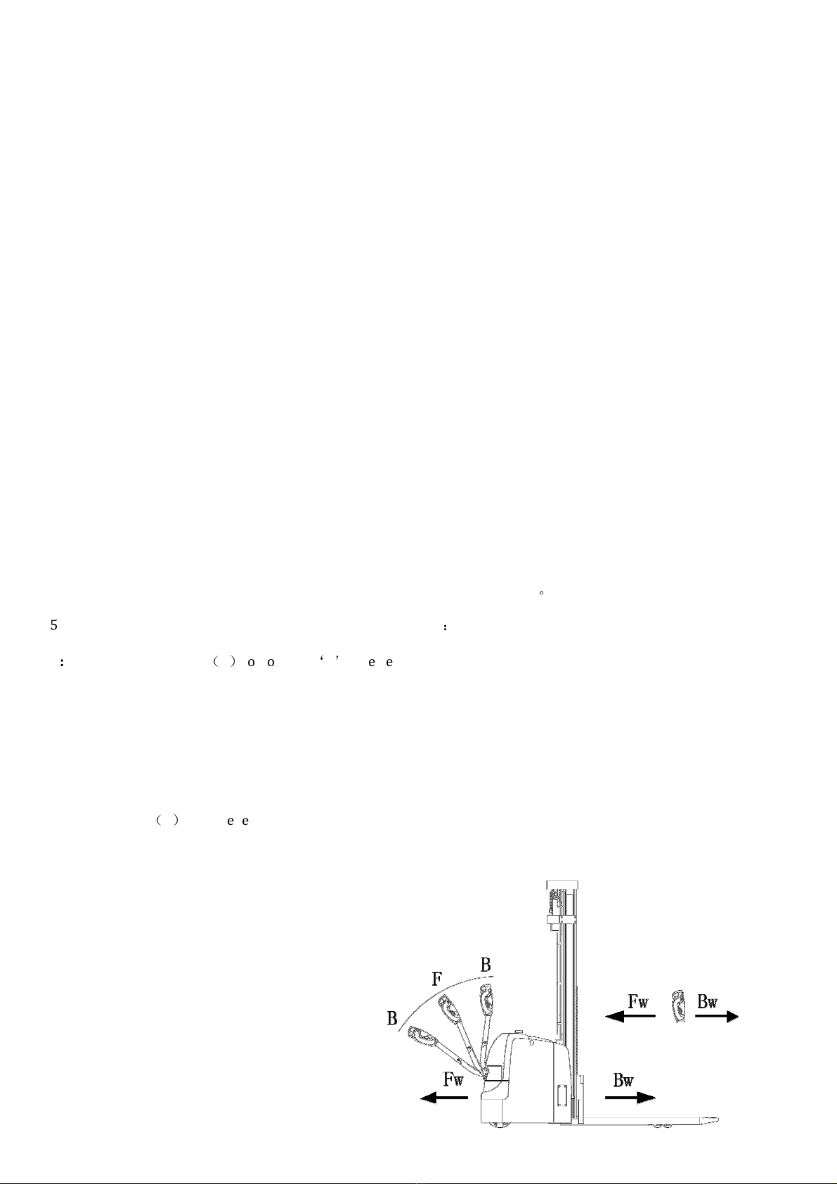
4.Operating principle.................................................................................................................................... 5
Operating mechanism diagram:.................................................................................................................. 6
5.Operating principle.................................................................................................................................... 6
5.1 Running system................................................................................................................................... 7
5.2 Steering system....................................................................................................................................7
5.3 Braking system.................................................................................................................................... 7
5.4 Operating System................................................................................................................................ 8
5.5 lectric System.....................................................................................................................................8
5.6 Hydraulic principle..............................................................................................................................9
6.Electrical schematic diagram....................................................................................................................9
7.Hydraulic Principle Diagram.................................................................................................................. 10
8.Operating instruction...............................................................................................................................11
8.1 Start, run and parking:...................................................................................................................... 11
8.2 The usage of emergency safety switch............................................................................................ 12
8.3 The usage of horn button.................................................................................................................. 12
8.4 Battery capacity indicator.................................................................................................................12
8.5 Handling stacking operation.............................................................................................................12
9.Maintenance...............................................................................................................................................13
9.1 Safety procedures for repair and maintenance.............................................................................. 13
9.2 Daily Maintenance............................................................................................................................. 14
9.3 Professional Maintenance Manual................................................................................................... 14
9.4 Maintenance, Recharging and Replacement of the accumulator.................................................. 16
10.Safety Precautions.................................................................................................................................. 19
10.1 general rules.................................................................................................................................... 19
10.2 Transportation and storage............................................................................................................19
10.3 Check before Using..........................................................................................................................20
10.4 Safe Operation................................................................................................................................. 20
11.Repair Manual......................................................................................................................................... 22
11.1 Malfunction analysis....................................................................................................................... 22
11.2 preparation work before repair.....................................................................................................22
11.3 check the oil content of hydraulic oil.............................................................................................23
11.4 preparation work before use after maintenance..........................................................................23

2
1.The eneral Introduction
B18 / B20 ,the stacker is equipped with a wide view lifting system, a new dc controller and other advanced
structures, and a high quality motor, traction battery and a high-power pump station motor. It has the characteristics
of superior performance, convenient operation, wide vision, flexible steering, reliable braking, good power
performance, less noise, no pollution, good appearance and so on.
This stacker is suitable for working on the smooth ground in warehouse, if not, please don’t use it.
The service environment
:
a. temperature: -10
℃
~ +40
℃;
b. the gradient less than 3%
;
c. when environment temperature at +40
℃
, the relative humidity should be less than 50%
,
At low
temperature
,
higher humidity is allowed;
d. ground should be hard and flat;
e. It is forbidden to use this car in corrosive environment such as flammable and explosive or acid base.

3
2.Proper usage
Please use the electric stacker accord to this specification.
This is a walkie type electric pallet truck with autonomous control, lifting and lowering is controlled by the
handle button. Improper use can cause personal injury or machine damage. Operators or operating companies need
to ensure proper using,
The Truck needs to be used on a firm, flat, intact surface and suitable surface, the truck is designed for indoor
use at room temperature from-10°C to +40°C
Use under light load without using permanent barriers or pits, It is forbidden to operate on the slopes.
Lifting or Carrying people is strictly prohibited.
It is prohibited to use this truck on lifting or loading ramps
。
The rated capacity is marked on the capacity label or nameplate. And the operator must pay attention to the
warming signs and safety instructions
Operating lighting must be at least 50LUX.
Modification
Any modification that may affect the truck rated capacity, stability, or safety operations must be approved in advance
by the Truck’s original manufacturer or Its authorized Manufacturer or its successor. This includes the effects of
changes such as Braking, steering, Visibility, and the addition of removable accessories.
After the manufacturer or its successor approves the modification or change, The capacity name plate, Label,
identification marks, operation and maintenance manual must be changed accordingly

4
3.Introduction of the product
3.1 Model Overview
This specification is for B18 series 3960LBS walkie type full powered stacker and B20 series 4400LBS
walkie type full powered stacker
(
follow as stacker
)。
3.2Model
EB18E

5
EB20E

6
Mode B18 B20
Load Capacity (lb) 4400 4400
The max. Lifting
height (in) 138 177
Load center distance (in) 24 24
Fork length (in) 45.3 45.3
Single fork width (in) 4.7 4.7
Overall fork height (in) 9.8-31.5 9.8-31.5
Lowered fork height (in) 3 3
Fixed leg length (in) 42 42
Adjustable legs (in) 45.5-59.1 45.5-59.1
Turning radius (in) 60 60
Overall length (in) 82 82
Max overall width (in) 61 61
xtended mast
height (in) 154 198
Lowered mast height (in) 91.3 83.6
Battery voltage V/ah 2*12/150 24/210
The charger V/A 24/20 24/30
Lifting motor V/Km
3kw.Lift speed,
laden/unladen:92/136mm/s;
Lowering speed,
laden/unladen:112/98mm/s
3kw.Lift speed,
laden/unladen:92/136mm/s;
Lowering speed,
laden/unladen:112/98mm/s
Driving motor
1.5kw.
Driving speed:
laden/unladen:4.0/4.2km/h
1.5kw.
Driving speed:
laden/unladen:4.0/4.2km/h
Service weight (in) 2100 3014

7
4.Operating principle
With battery as power producer and controlled by electrical and hydraulic, trucks can do some actions like walking, turning,
pallet fork lift, etc.
Operating mechanism diagram:
1.Switch for lifting and lowering 2.Switch for driving 3.Belly switch 4.Horn
5.Coulombmeter

8
5.Operating principle
5.1Running system
The truck is powered by a battery, which is reali ed by controlling the AC motor on the drive wheel. The speed of walking
is reali ed by frequency conversion control motor speed, which is controlled by the accelerator.
Gear box in the factory has been posited with enough gear lubricating oil. And please change the gear lubricating oil every
1000 hours under normal circumstances.
If you hear abnormal sound from gear box when using, please stop and check immediately. If there are bearing failure or
some problems in gear, please replace and repair them.
5.2 Steering system
The operating handle drives the rotation direction sensor which can send out the turn signals that makes the truck turn
around.
5.3 Braking system
Braking performance depends on road conditions and vehicle load conditions
。
5.3.1 The brake function can be activated by the following way
:
A:Move the Fahrschalter
(
2
)
to position
‘
0
’
,The vehicle brake until it stops.
B:Move the travel switch directly to the opposite direction, vehicle regenerative braking until it began in the
opposite direction.
C:Vehicle braking, if the handle is moved up and down to the braking area (" B "). If the release handle, the handle
automatically moves to the braking area (" B ") vehicle brake until it stops.
D:Belly switch
(
3
)
Can prevent the operator will be squeezed, if the button to activate, behind the vehicle to slow
down or start to (' Bw) driven a short distance, then stop. If the handle is in operation area and vehicles is not driving,
please consider this button to throw this situation.

9
5.3.2Brake operating principle
As shown in the following figure, the brake consists of magnetic yoke assembly 6, excitation coil 7, spring 2, brake
disc 5, armature 1, gear sleeve 4, installation screw 3, etc. The brake is mounted on the end cover of the motor and
the mounting screw is adjusted to the specified air gap value. The gear sleeve is fixed on the shaft, its outer tooth and
the inner tooth of the brake disc cooperate, when the torque is transferred, the brake disc can move axially on the
gear sleeve.
When the actuator coil 7 is energized, the coil produces a magnetic field that causes armature 1 to draw toward the
magnet yoke assembly 6 and armature 1 to detach (release) from the brake disc 5. At this time motor drive shaft
with brake disc 5 start and operate normally. When coil 7 is cut off, the magnetic flux disappears, armature 1 is
released, and spring 2 presses armature 1, and compresses the friction plate on the brake disc, generating friction
force to achieve the purpose of braking.

10
5.4 Operating System
The main working part of truck is fork, which are used to carry the pallet or cargo for transport and short distance
transportation. The expansion of the cylinder is realized by the control of the operating handle, and the pressure oil
is provided by the pumping station.
5.5 Electric System
The electrical system includes walking and operation control. The truck use AC electric control assembly. The
meter has a battery indicator. When the battery power is too low, the electric meter will cut off the starting control
line of the oil pump motor. The moving truck can only walk without lifting the fork, and the prompt should be
charged immediately. The motor of oil pump is the dc motor for 5 minutes, so the pump motor is not suitable for
long running. That is, the lifting movement should have time interval, cannot continuously carry on, otherwise would
make the motor heating, even burn.
Special note: when the truck is used for a long time, the starter of the oil pump motor may fail, and it can't be
broken after being sucked or closed. The latter is not throw control handle, the oil pump motor is kept in the rotation,
should immediately stop at this moment, to cut off the power supply (unplug battery plug-in), make the oil pump
motor stop running, and promptly replace the starter.
5.6 Hydraulic principle
The oil pump motor drives the gear pump to provide hydraulic power, lifting oil cylinder is responsible of fork’s
lifting and lowering, The control of the lift oil road is controlled by the buttons on the operating handle, The lifting
action is controlled by a single action oil circuit on the valve block. This model of the hydraulic system pressure can
only be adjusted on the valve block, has been debugging good, before they go out after they leave the our company
after-sales personnel or professional maintenance personnel are strictly forbidden to adjust themselves, so as to
avoid safety accident.

11
6.Electrical schematic diagram

12
7.Hydraulic Principle Diagram

13
8.operating instruction
Before operation, please be familiar with the function of each switch/button on the instrument panel.
8.1 Start, run and parking:
1).Insert the key into the key switch, turn to the right, pull the emergency power safety switch up, open the control
circuit.
2).Forks rise above ground about 10 cm
3).Turn on the travel switch slowly, till the requested speed
4).Any fault of the truck happening during operation, need to cut off the power immediately, and press the red
emergency power switch down.
5).Avoid to take a sudden turn during driving the truck.
6).Using stacker full load climbing a slope, need to know the condition of the slope, and press the travel switch as
much as possible to get a maximum grade ability.
7).When stop driving, put the fork in the bottom, press the emergency switch down, and pull out the key.
8.2The usage of emergency safety switch
Press the emergency safety switch down, then the truck is powered off. Method to open it: pull the red button up.
mergency safety switch is made of plastic, too much pressure may damage it.
8.3 The usage of horn button.
Press the horn button in the center of handle to notify people around.
8.4 Battery capacity indicator
The stacker battery capacity indicator has electricity capacity display function.

14
8.5 Handling stacking operation
1). How to transport the goods pile on weight
Will forklift drive to the front of the items which need to carry slowly , make fork parallel to the ground, lifting the
fork to height, it can be inserted into the freight insert goods fork and move forward slowly, when the goods
completely inserted into the goods after parking and stepping on the brakes, manipulating ascend handle, the heavy
lifting to a certain height, make the door frame lean back, slowly astern, don't touch the adjacent goods, when weight
completely left the heap of goods, reduce the goods to the right position, then walk for handling.
2). The weight on the heap of goods
Will weight low, lean back door frame, to storage goods moving close to the pile of deceleration, when determining
forklift with pile goods into a linear state, stepping on the brakes slowly adjust the door frame Angle to the vertical
state, increase the weight will be slightly more than goods pile height, and then slowly driving forklift driving
forward to pile top stop. Heap controls control lever slowly, once handling stacked drags the weight, the goods fork
to the hollow position, from the weight of the goods fork, make sure barrier-free backward position, can retreat.
After goods fork out weight reduce goods fork, door frame round of the reentry after handling operation.
9.Maintenance
The parts on the vehicle, especially safety devices, shall not be modified without permission, and the driving speed of
the vehicle shall not be changed. All parts supplied by the original manufacturer are subject to strict quality
inspection. To ensure the safety and reliability of the vehicle, please use the original accessories. Replacement parts,
including all oil, must be collected and processed in accordance with local environmental and health laws and
regulations.
9.1Safety procedures for repair and maintenance
Maintenance technician: The maintenance and service should only be performed by special personnel trained by
the manufacturer. After the technician sent by after-sales department of the manufacturer completed maintenance
and servicing work, they should sign on the service log.
Cleaning Operation: Flammable liquid cannot be used for cleaning the stacker. Before cleaning, take safety
precautions to prevent electric sparks (e.g. sparks caused by short circuit). When operating the accumulator,
connectors on it must be disconnected. Use soft air suction or compressed air, non-conductive and anti-static
brushes to clean electric and electronic components.
Operation of Electric System: Operation on the electric system should only be performed by specially trained
personnel. Before performing any operation on the electric system, precautions must be made to prevent electric
shock. When operating the accumulator, connectors on it must be disconnected.

15
Installation: When repairing or replacing hydraulic components, electric and electronic components, make sure to
install them back to their original positions.
Wheels: Quality of the wheels has significant effect on stability and driving performance of the stacker. Modification
on wheels can be performed only with the approval from the manufacturer. When replacing wheels, ensure that the
stacker is levelled as delivery state (wheels must be replaced in pairs, i.e. replace right wheel together with left one).
Lifting chain and rollers: Chain and rollers will be worn quickly without good lubrication. Perform periodic
lubrication according to following maintenance table. Shorten the lubrication period under adverse operation
conditions (such as in dusty and hot environment).
Hydraulic oil pipe: The oil pipe must be changed every 6 years. When change the hydraulic assembled parts, the oil
pipe should be also changed.
9.2 Daily Maintenance
9.2.1 Check every pole, every cable and their covers.
9.2.2Check if the accumulator box is secured.
9.2.3 Check the stacker for oil leakage.
9.2.4 Check the chain, rollers, fork, oil pipes and horn.
9.2.5Check the brake.
9.2.6 Check the wear and tear of drive wheels and loading wheels.
9.3 Professional Maintenance Manual
It is very important for safe operation of the truck to perform overall professional maintenance. Failure in
performing maintenance according to specified interval may cause malfunction of the truck, and potential risk to
human and equipment.
Maintenance periods listed in this manual apply to single shift a day under normal operation conditions. If using
in dusty environment, the ambient temperature varies remarkably or in multi-shift situation, the maintenance
period has to be shortened.
Maintain the truck according to following maintenance list. Maintenance periods are as follows:
W1 = very 50 work hours, but at least once a week.
M3 = very 500 work hours, but at least once every three months
M6 = very 1000 work hours, but at least once every six months
M12 = very 2000 work hours, but at least once every 12 months

16
Additional operations should be performed in trial run period:
(In initial 50 – 100 working hours or after two months)
— Check the nuts on the wheels, and tighten them if necessary.
— Check the hydraulic components for leakage, and tighten them if necessary.
—Replace the hydraulic filter.

17
Maintenance interval
●
W A B C
Brake 1.1 Check the air gap of the electromagnetic brake
●
lectric
system
2.1 Check the function of operation switch, display equipment
and component
●
2.2 Check alarm systems and safety devices
●
2.3 Check the cable for damage. Whether the terminal is firm.
●
2.4 Check the function of micro switch setting
●
2.5 Check the controller and the PS controller
●
2.6 Cable and motor fixation
●
Power
3.1 Check battery
●
3.2 Check the charging connector for battery
●
3.3 Check whether the connection of the battery cable is tight,
and smear the electrode with grease if necessary
●
Driving
system
4.1 Check the gearbox for noise
●
4.2 Check the driving mechanism and grease, check the reset
function of the operating handle
●
4.3 Check the drive wheels and bearing wheel for wear and
damage
●
4.4 Check wheel bearings and fixtures
●
Massive
structure
5.1 Check the frame for damage
●
5.2 Check the label for completeness
●
5.3 Check the fixation status of lifting mast
●
The
hydraulic
system
6.1 Check the hydraulic system function
●
6.2 Check that hoses, pipes, and joints are tight and that seals
are not damaged
●
6.3 Check cylinder and piston for damage, seal and fixation
●
6.4 Check load chain Settings and re-tighten if necessary
●
6.5 Visually inspect mast roller and inspect roller surface for
wear
●
6.6 Inspect cargo fork and load parts for wear
●
6.7 Check oil level
●
6.8 Renewed hydraulic oil
●
Maintenance

18
9.4Maintenance, Recharging and Replacement of the accumulator
The truck must be parked in a safe location before any operation on the accumulator.
9.4.1 Maintenance Technician
Battery charging, maintenance and replacement must be operated by qualified professionals. The user manual,
supply preparation and charging requirements must be carefully read before the preparation operation.
9.4.2 Fire protection measures
When operating the battery, smoking and open flame are strictly prohibited. Storage batteries and charging should
be kept away from combustible materials, and should be kept at least 2 meters away. Places where batteries are
placed should be well ventilated and equipped with fire protection facilities.
9.4.3 Battery maintenance
1) Keep the nuts on every battery cell dry and clean. Tighten every terminal and cable end, and brush them with
grease to prevent corrosion. Naked cable ends and terminal posts should be covered with a skid-proof insulating
cover.
2) very two cells should be well-connected. Check the nuts on each pole, if loose, tighten the nuts.
3) Keep the surfaces of accumulator clean and dry. After the completion of recharging, clean spilled acid with cotton
yarns or brush. And clean with wet towel if necessary.
4) Over recharging and over discharging should be avoided, and fast charging and insufficient recharging are also
not allowed. Otherwise life span of the accumulator may be affected.
5) Do not put conductive objects including metal tools on the accumulator, or short circuit or even explosion may be
caused.
6) Never spill any hazardous liquid or solid material on surfaces of the accumulator. When using a densimeter or a
thermometer, make sure the surface is clean and clear.
7) Recharge the discharged accumulator in time. Delayed recharging may damage the accumulator. Do not delay
recharging more than 24 hours. Recharging of the accumulator may not work outdoors in cold weather. In this case,
move it indoors to perform recharging.
8) If the accumulator will not be in use for a long time, it should be recharged and discharged once every month and
it should be fully recharged every time.
9) During recharging or using, the liquid level of electrolyte lowers because of water evaporation, so pure water
should be added. It is not allowed to add electrolyte with a specific weight of 1.280.

19
10) If individual cell fails, identify the cause and repair the cell immediately. Replace the cell when it cannot be
repaired.
11) The site for recharging should be well ventilated. It is prohibited to smoke or use open fire, avoiding the risk of
hydrogen explosion.
12) The electrolyte in accumulator is toxic and corrosive. For this reason, always wear working suit and protection
glasses to protect your body from contacting the electrolyte in accumulator.
13) If your clothes, skin or eyes are spilled with acid liquid in accumulator, flush with large amount of clean water.
For skin and eyes, flush with large amount of clean water and also seek doctor’s treatment immediately. Acid spillage
must be neutralized and treated immediately.
14) The weight and dimensions of the accumulator have remarkable effect on stability of the stacker. Therefore do
not modify the type of accumulator without approval from the manufacturer.
15) Never discharge in large current, for example, performs travelling and lifting simultaneously.
9.4.4 Disposition of worn-out accumulators
Worn-out accumulators should be recycled according to local regulations, and stored in specified zone or cast-off
treatment zone. These works should be done by qualified specialized companies.
9.4.5 Specification of the accumulator
Battery Charger
Rated power
:
24V
Load capacity
:
2*12V/150Ah( B18 )
24V/210AH( B20 )
Input
:
195/265VAC
50/60Hz
Output
:
24V/20A( B18 )
24V30A( B20 )
The battery's non-insulated terminal must be protected by an insulating cover. When the battery is connected and
connected to the socket, the vehicle must be cut off and the switch in the closed position. When replacing or
assembling the battery, make sure the battery is securely fixed in the battery box.
9.4.6 Storage, transportation and installation of the accumulator
The truck must be parked on the level ground steadily. To prevent short circuit, naked cable ends and the terminal
posts should be covered with insulated covers. When pulling out the accumulator, properly arrange removed
accumulator's connectors and cables without blocking access of the accumulator.
9.4.7 Battery power indicator
Battery power display table: ten article showing represent 100% of the battery. With the consumption of battery
capacity, the glowing article shows will be from top to down.
Other manuals for EB18E
1
This manual suits for next models
1
Table of contents
Other EKKO Forklift manuals