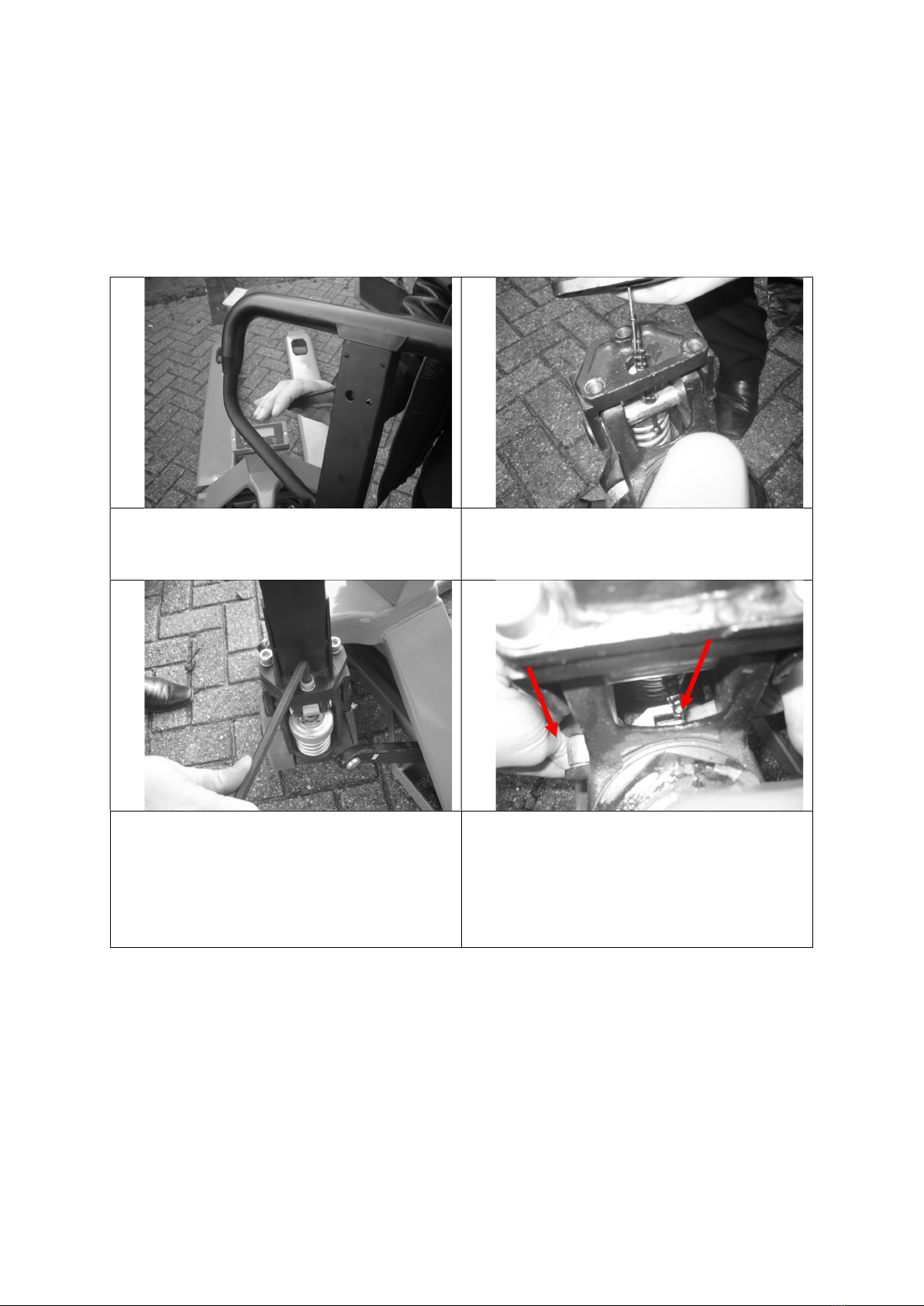
Ravas 100 Series User manual

1
RAVAS-110
OWNERS MANUAL
We would like to inform you about the fact that this RAVAS product is 100% recyclable on the basis
that the parts are processed and disposed off in the right manner.
More information can be found on our website www.ravas.com.
Rev.20201102
Printing/typographical errors and model changes reserved

2
OPERATORS MANUAL
RAVAS 110
INDEX PAGE
1. Safety Instructions 3
2. System Setup 4
3. Operation Manual 7
3.1 Accurate Weighing
3.2 Touch Panel Display
3.3 Net + Tare = Gross
3.4 On / Off
3.5 Error Messages
3.6 Zero and Tare Functions
3.7 Manual Tare
3.8 Summing
3.9 Total and reset
4. Trouble Shooting 16
5. Calibration 19
6. Parameter Settings 21
Contact Us:
salesoffice@ravas.com
www.ravas.com

3
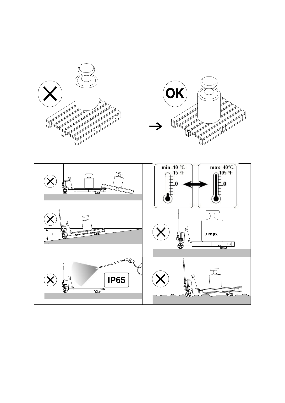
1. SAFETY INSTRUCTIONS
1. NEVER lift a heavy load with just the tip of the forks. This could damage the electronic
weighing elements permanently.
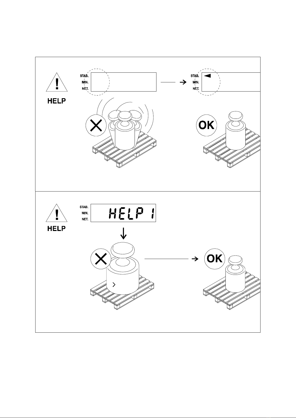
2. NEVER weigh without a pallet. This could affect the accuracy of the weighing result.
3. The unit may be loaded with weights up to 5000 lb. However we advise you not to move any
weights above 1650 lb. (750 kg) with the unit. RAVAS is not responsible for injury that may
result when moving heavy loads.
4. Use caution in the vicinity of moving parts - these parts can cut and/or crush hands, arms, feet
and legs.
5. Always center the load you are lifting on both the forks.
6. Do not operate the weighing system on ramps, inclines or declines, without the addition of our
optional parking brake.
7. Do not operate the weighing system while others are on or near the unit. No riding!
8. All modifications must be approved in writing from the supplier, prior to any work being
completed.
9. It is the sole responsibility of the purchaser to train their own employees in the proper use and
maintenance of this equipment.
10. Do not operate this unit unless you have been fully trained of its capabilities.
11. Do not use the weighing system in potentially explosive areas.
12. Do not carry passengers with the truck.
13. Do not weld or make changes to the weighing system without consulting the supplier.
14. Do not lift unstable loads.
15. Check the accuracy of the scale on a regular basis to prevent faulty readings.
16. Only trained and authorized personnel are allowed to operate the truck.
17. Always follow the operating, maintenance and repair instructions of this truck and ask the
supplier when in doubt.
18. Never lower loads if you are unsure you can place the goods on a stable surface. Personal
injury may result from placement on an unstable environment.
19. Always remain with the scale during dosing applications. Incorrect lifting of the pallet can
cause overflowing.
20. RAVAS USA is not responsible for errors that occur due to incorrect weighings or inaccurate
scales.

4
2. SYSTEM SET UP
Installation of pump handle (Your local dealer may have done
this)
Make sure the lever is pushed down to the
“pump” position.
Thread the chain through the hole in the
triangle and through the hole in the axle.
Place the handle bar onto the triangle and
insert the bolts.
Tighten the bolts firmly.
Push the silver part “A” on the outside of the
pump downwards.
At the same time; insert the chain into
the open side of the slot “B” on the
inside of the pump.
A
B

5
Installing the batteries (Your local dealer may have done this)
The power supply to the system takes place through 4 AA batteries. When used normally, the
batteries will last for about 1 year.
When the voltage level of the batteries is running low, the display will show “LO-BA“. When the
batteries are completely empty, the weighing system shuts off.
To replace the batteries:

6
3. OPERATION MANUAL
INDEX PAGE
3.1 Accurate Weighing 7
3.2 Touch Panel Display 8
3.3 Net + Tare = Gross 8
3.4 On / Off 9
3.5 Error Messages 10
3.6 Zero and Tare Functions 12
3.7 Manual (Preset) Tare 13
3.8 Summing 14
3.9 Total and reset 15

7
3.1 Accurate Weighing
-2

8
MIN
.
3.2 Touch Panel Indicator
3.3 Net + Tare = Gross
1 2 3

9
3.4 On / Off

10
3.5 Error Messages
max.

11

12
3.6 Zero and Tare Functions

13
3.7 Manual Tare Entry

14
3.8 Summing

15
3.9 Total and Reset

16
4 TROUBLESHOOTING
No power Change
batteries
4x AA batteries cells See page 11
Batteries have been entered the wrong way.
Accuracy No
repeatability
Check if there is a
mechanical problem.
Load left and right fork with for example body weight
and see if weight changes when you are in different
positions on the scale.
There should not be a difference larger than 2 lb.
If there is a bigger difference then 5 lb you have a
load cell or a mechanical problem.
To make sure it is a mechanical problem, repeat test
with a heavy load on the scale, Lift a pallet with 2000
or 3000 lb.
Reset Indicator for 0 lb using the tare function.
Load corners with body weight by standing on or on
the sides of the pallet. If readings change more than 5
lb you have a mechanical problem.
The push rods in the forks may not interfere with the
load cells. Take of the fork shoe by unscrewing the
nuts on the bottom side of the pallet truck.
Push the pushrods sideways towards the load cells to
see if they come in contact with the load cells: see if
they can interfere with the load cells.
With the forks lifted half way up, the brackets for the
loading wheels may touch the fork shoe. By taking off
the fork shoe, Scratches will show if it does and where
it does.
Check if bolts are loose.
Check the load cells. If
one is broken or gives
more or less signal
than the others, the
scale will give different
reading depending
how it is loaded.
To be sure that it is not a mechanical problem, load
the load cells directly. Take off the fork cover. Try to
apply weight 25 to 50 kg / lb, direct onto each load
cell. If the indicator shows the same reading, the load
cells are OK.
Tap with a hammer onto the load cells. Do not be
afraid to break it. Repeat test for each load cell.
Measure resistance with ohm meter between wires
and load cell body. Do this with the other load cells
disconnected from indicator. No resistance is allowed.
The load cells should have +/- 350 ohm between the
signal wires: yellow and green, and excitation wires,
black and red.
Check cables Bad connections will cause changes when moving the
scale.
Bend and move the cable briskly especially where the
cable is moving continuously while lifting. While doing
so, look at the display to see if it reacts to the
movements.

17
The potentiometers
with which we
calibrate the output of
the load cells, are
mechanical parts
therefore, higher risk
components
Move the board and but pressure with fingers on the
potentiometers while looking at the display to see if it
reacts. Do not touch the contact itself.
Not linear Check if it is load cells
or indicator
Load cells or indicator are very rarely the cause of this
problem. Easiest way to check is by changing the
indicator temporarily. If problem is not solved when
changing the indicator, the problem is the load cell,
cable or mechanics
Check cable Very rarely the cause. Maybe in a lift truck.
Instability With no load it
is most of the
time humidity,
bad connection
or component r
bad shield.
Check for humidity Check for water marks on the indicator board or load
cell connections (potentiometers).
Check the indicator. Sometimes the indicator will show a weight when load
cells are disconnected. If you do this and the indicator
becomes more stable, it is most likely elsewhere in
the system.
Check visually for traces of oxidation. If found heating
the solder contacts can solve the problem.
Check cables. In
warehouse and lift
truck the cable is
working all the time
when following the
lifting movement. It
may be worn or
damaged. Changing
temperatures and
chemicals have an
effect on the lifetime of
a cable.
Bad connections will cause changes when moving the
scale.
Bend and move the cable briskly especially where the
cable is moving continuously when lifting. While doing
so, look at the display to see if it reacts to the
movements.
The potentiometers
with which we
calibrate the output of
the load cells are
mechanical parts and
are sensitive to
humidity, shocks and
vibration.
Move the board and but pressure with fingers on the
potentiometers while looking at the display to see if it
reacts. Do not touch the contact itself.
Check the load cells. If connected independently to the indicator, it can be
checked which one is unstable and which one is not.
With load Check mechanics.
Function
error
No reaction
when pushing
keys
Check the touch panel
Test can be done by making short cut on connection
of the touch panel to simulate a key being pressed.
Check for wear of broken contacts in the flat cable
going to the indicator board
Lock up Take out the batteries and replace to see if it starts up
afterwards.

18
Not summing Operator error
.
Load is not stable.
Scale needs to be unloaded before accepting new
print.
System will not print weights that are smaller than the
graduation.
HELP
messages
HELP 2 Scale is overloaded Take load from scale. If there is no load do the same
checks as you do with HELP 3 and 7.
Help 3 or 7 Load cell signal too
high or too low.
Check cables for damage. Move the cable while
looking at display to see if indicator reacts.
Measure load cells to see if they are fine.
Check the excitation signal of the indicator
Help 4 Out of zero range Zero calibration needed.

19
5 CALIBRATION
CALIBRATION INSTRUCTIONS INDICATOR 110
DETERMINE THE SOFTWARE VERSION
Switch the system on.
❏ The indicator shows the following sequence:
8888.8 (testing LCD segments)
7.x (software version)
13425 (the calibration number)
(current weight, standard weigh mode).
DEFINING ZERO
Unload the system.
Switch the system on.
Push the 0/T key for about 8 seconds.
❏ The display counts down from AF 08 to AF 00.
❏ The indicator shows which percentage of the total capacity has been zeroed, e.g. AP 6.4. This
percentage should not be higher than 20.
❏ The zero point has now been defined, the system automatically returns to standard weighing
mode.
CALIBRATION
The indicator offers the possibility to enter a maximum of three calibration points (multiple point
calibration). The advantage is that even weighing systems with bad hysteresis can be calibrated within
specifications.
Since these instructions are often used in the field, where it is difficult to calibrate various points, we
will start with the explanation of single point calibration.
SINGLE POINT CALIBRATION
Deletion (resetting to zero) of earlier calibrated points
Push the PT key for about 18 seconds (this may be 8 seconds on older versions)
❏ The display will go blank until calibration mode has been reached.
❏ The indicator shows the value of the first calibration point, the lowest indication bar (on the left
of the display) is flashing.
Use the and keys to see the three earlier programmed values on the screen by moving the
indication bar up and down.
❏ When the lower indication bar is lit, the first (lowest) value is shown
❏ When the higher indication bar is lit, the second (middle) value is shown.
❏ When both indication bars are lit, the third (highest) value is shown.
❏ When calibrating only one point the second and highest values should be returned to zero.
Press the or key until the middle calibration value is in the screen.
❏ The higher indication bar is flashing.
Press the 0/T key.
❏ The first segment is flashing.
Use the and keys to set the flashing segment to zero.
Change to the next segment by pressing the 0/T key.
Set all the segments to zero until the indication bar is flashing.
Press the or key until the highest calibration value is in the screen.
❏ Both indication bars are flashing.
Repeat the process until all the segments are set to zero.

20
Single point calibration
Return to the lowest value.
❏ The indicator shows the value of the first calibration point, the lowest indication bar is flashing.
Load the weighing system with a known weight and enter this weight on the indicator by pushing
the 0/T key shortly.
❏ The first segment starts flashing.
Use the en keys to change all segments, confirming the value per segment by pressing the
0/T key, until the proper weight has been entered.
❏ When each segment has been corrected, the lower indication bar will flash again.
Confirm the entered weight by pressing the 0/T key for 3 seconds.
❏ The display counts down from AF 08 to AF 00, the first calibration point has been set.
Leave calibration mode by pressing the or key until AP XX appears.
❏ This number indicates the calibration sensitivity percentage, e.g. AP 07.
Press the 0/T key until the display goes blank.
MULTI-POINT CALIBRATION
Push the PT key for about 18 seconds (this may be 8 seconds on older versions).
❏ The display will go blank until calibration mode has been reached.
❏ The indicator shows the value of the first calibration point, the lowest indication bar is flashing.
Load the weighing system with a known weight and enter this weight on the indicator by pressing
the 0/T key shortly.
❏ The first segment will start flashing.
Use the en keys to change all segments, confirming the value per segment by pressing the
0/T key, until the proper weight has been entered.
❏ When each segment has been corrected, the lower indication bar will flash again.
Confirm the entered weight by pressing the 0/T key for 3 seconds.
❏ The display counts down from AF 08 to AF 00, the first calibration point has now been set.
Press the key.
❏ The higher indication bar will start flashing and the indicator shows the value of the second
calibration point.
Load the weighing system with a higher known weight and enter this weight on the indicator, in the
same way as described above.
❏ Upon confirmation the second calibration point will be set.
Repeat the procedure for the third calibration point.
Leave calibration mode by pressing the or key until AP XX appears.
❏ This number indicates the calibration sensitivity percentage, e.g. AP 07.
Press the 0/T key until the display goes blank.
After calibration, the indicator automatically switches to a small graduation. Only after
switching the indicator off and turning it on again, will the indicator activate the chosen
graduation.
Attention: in order to be able to practically start using the new parameter and calibration settings,
these new data first need to be saved into the memory of the indicator.
How to do this:
- after the desired parameter and/or calibration changes have been made, use the OFF key to switch
off the indicator
- during the switching off procedure all new changes will be stored in the memory of the indicator and
will become active when the indicator is re-started afterwards.
This manual suits for next models
1
Table of contents
Other Ravas Forklift manuals