manuals.online logo
Brands
  1. Home
  2. •
  3. Brands
  4. •
  5. VEVOR
  6. •
  7. Fan
  8. •
  9. VEVOR BATHROOM MASTER User manual

VEVOR BATHROOM MASTER User manual

Technical Support and E-Warranty Certificate
www.vevor.com/support
BATHROOM MASTER
USER MANUAL
We continue to be committed to provide you tools with competitive price.
"Save Half", "Half Price" or any other similar expressions used by us only represents an
estimate of savings you might benefit from buying certain tools with us compared to the major
top brands and does not necessarily mean to cover all categories of tools offered by us. You
are kindly reminded to verify carefully when you are placing an order with us if you are
actually saving half in comparison with the top major brands.
- 1 -
<Picture Only For Reference>
Have product questions? Need technical support? Please feel free to
contact us:
Technical Support and E-Warranty Certificate
www.vevor.com/support
NEED HELP? CONTACT US!
This is the original instruction, please read all manual instructions
carefully before operating. VEVOR reserves a clear interpretation of our
user manual. The appearance of the product shall be subject to the
product you received. Please forgive us that we won't inform you again if
there are any technology or software updates on our product.
BATHROOM MASTER
- 2 -
READ & SAVE THESE INSTRUCTIONS
TABLE OF CONTENTS
Package Contents
Safety Information
Preparation
Installation Instructions
Maintenance
Troubleshooting
TYPICAL INSTALLATION
- 3 -
PACKAGE CONTENTS
- 4 -
Safety guidelines
Please be sure to comply with :
1. Power off before maintenance.
2. This product is not suitable for maintenance and use by individuals with
disabilities, intellectual disabilities, or mental disorders, or those lacking
experience or common sense (including children), unless used under the
care or guidance of someone responsible for their safety. Children should
be taken care of to prevent using the product as a toy.
3. To avoid causing harm to you and others, we have listed the following
safety precautions that must be followed. Please refer to the following
content for the meanings of various signs.
Ignoring or misunderstanding these signs can result in two situations:
The content classification that must be followed, distinguished by
symbols, is as follows:
WARNING: The content represented by this sign is "May cause
death or serious injury to personnel"
Attention: The content indicated by this sign is "May cause personal
injury and other damage to items"
This sign indicates a prohibited item
This flag represents a mandatory matter
- 5 -
Installation precautions
NOTE: For installation personnel to read
WARNING
Must be grounded. Otherwise, when there is a malfunction or
leakage, electric shock may occur.
During installation, maintenance, and upkeep, the power supply
must be disconnected. Otherwise, it may cause electric shock.
Installation must be carried out by professionals or trained
personnel with equivalent professional knowledge and
skills in accordance with national wiring regulations.
Otherwise, it may cause leakage, electric shock, and fire
due to incorrect wiring, twisted wiring, and wire clamping.
The installation of the product should ensure that people in the
bathtub or shower area cannot reach the switches and other
controllers.Otherwise, it may cause electric shock
It is necessary to prevent gas from flowing back into the room
from open airways or other open flame equipment. Otherwise,
it may cause a fire
When installing, a "full pole power switch" with a contact
distance of no less than 3mm must be installed in the power
supply line to connect or disconnect the main power supply. Its
rated load capacity should not be less than 250V~15A and
should be installed outside the bathroom for easy operation.
Otherwise, it may cause a short circuit and lead to a fire.
Ensure that the power cord is installed in place. Otherwise, it
may cause a fire.
- 6 -
It is prohibited to use power sources other than the rated voltage
(120V~, 60Hz). Otherwise, it may damage this product and
cause a fire.
To avoid danger caused by incorrect reset of the thermal circuit
breaker, the product cannot be powered through external
switching devices. For example, a timer or a circuit connected to
a universal component for timing on and off. Otherwise, it may
cause a fire.
Prohibit installation near curtains and other combustible
materials. Otherwise, it may ignite combustible materials.
It is prohibited to use this product under a power outlet.
Otherwise, it may cause electric shock or fire.
Do not remove the circuit board cover during installation and
use. Otherwise, it may cause electric shock or fire.
Please have two people carry out the installation of the product.
The installation of components and the machine body must be
firm. Otherwise, the product may fall and cause injury.
When special components such as hardware are installed,
special components should be used. Otherwise, the product
may fall and cause injury.
The building structure and suspension rods for installing
products must have sufficient installation strength to ensure that
they can bear a strength greater than 5 times the weight of the
product. If the installation strength cannot be guaranteed,
please take reinforcement measures. Otherwise, the product
may fall and cause injury.
It is prohibited to modify this product. Otherwise, the product
may fall and cause injury.
- 7 -
Safety Information
Please read and understand this entire manual before attempting to
assemble, operate or install the product.
1. Always disconnect the power supply prior to servicing the fan, motor or
junction box.
2. Installation work must be out by a qualified person(s) in accordance to
all local and safety codes including the rules for fire-rated construction.
3. Follow all local building, safety and electrical codes, as well as
NEC( National Electrical Code) and OSHA( Occupational Safety and
Health Act).
4. Electric service supply must be 120 volts, 60 hertz.
5. This unit must be properly grounded.
6. Do not bend or kink the power wires
7. Exercise care to not damage existing wiring when cutting or drilling
into walls or ceilings.
8. Sufficient air supply is required for proper combustion and the
exhaustion of gases through the chimney(flue) of fuel burning
equipment to prevent back-drafting. See the standards of
NFPA( National Fire Protection Association) and ASHRAE( American
Society for Heating Refrigeration and Air Conditioning Engineers ) and
the local building code authorities
9. Do not use this fan with any solid state control device, such as a
remote control, dimmer switch or certain timers. Mechanical timers are
not solid state devices
10. This ventilation fan is approved for use over a bathtub or shower when
installed in a GFCI protected circuit. Do not use fans over a bathtub or
shower that are not approved for that application and marked
accordingly
11. Do not install in a cooking area
12. Do not use to exhaust hazardous or explosive vapors.
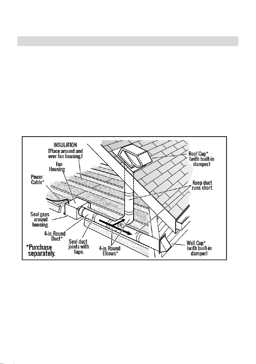
13. Fans should always be vented to the exterior and in compliance with
local codes
14. Do not install in a ceiling with insulation greater than R50
- 8 -
15. Duct work should be installed in a straight line with minimal bends
16. Duct work size must be the same size as the discharge and should not
be reduced. Reducing the duct size may increase fan noise.
17. Prior to servicing or cleaning this unit, shut off power supply at the
panel and lock to prevent the power from being turned on. If the panel
cannot be locked, clearly mark the panel with a warning tag to prevent
the power from being turned on
18. Use this unit in the manner intended by the manufacturer. If you have
any questions, please call customer service.
Installation Requirements
- 9 -
Installation Instructions
1. Choose the location for your fan in the ceiling. For best possible
performance, use the shortest possible duct run and a minimum
number of elbows.
2. Cut an opening measuring 11.3 inches x 10.3 inches at the selected
location. ( See the Fig.1.)
3. Fix two wooden boards with a thickness of over 15mm and align the
cut holes. Consistent with the installation direction shown in the
diagram. ( See the Fig.2.)
Fig.1.
Fig.2.
- 10 -
4. Loosen the screws and remove the power box cover, pass the power
cord through the ceiling. Connect the power cord according to the
wiring diagram, and then lock the power box cover with screws. (See
the Fig.3.)
WIRING DIAGRAM:
Fig.3.
- 11 -
5. Push the fan housing into the ceiling hole and secure it with 8 wooden
screws (locked through two layers of ceiling). ( See the Fig.4.)
6. Install the plastic plate into the duct connector. Then install the duct
connector into the fan housing and tighten the screws. ( See the
Fig.5.)
Fig.4.
Fig.5.
- 12 -
7. Install a circular 4 in. duct (not included) and secure it with duct tape or
clamps (neither included). Finish ceiling work. Ceiling hole should be
aligned with edge of fan housing.( See the Fig.6.)
8. Carefully connect the light wires. ( See the Fig.7.)
Fig.6.
Fig.7.
- 13 -
9. Align the two clips of the grille with the slots on the fan housing and
snap them in. ( See the Fig.8.)
10. Align the two screw pillars of the grille with the two screw pillars in the
fan housing, push the grille to level with the ceiling, and finally lock it
with two M4x 12 screws. ( See the Fig.9.)
Fig.8.
Fig.9.
- 14 -
11. Press the silicon sheet plug into the two screw holes. All installations
completed. ( See the Fig.10.)
Remote Control Instructions
NOTE: Please refer description diagram.
1. Main switch:
1.1. The initial state of the "Main switch" is off by default: the power is off;
1.2. Press the "Main switch" button once: the power is turned on;
2. Light switch:
When the wall control switch is turned on, the default light is on, and the
light is on: neutral light;
3. Light color temperature adjustment ( light CT ) :
When the light is Turn on, use the "Light color temperature adjustment"
button to adjust the color temperature;
3.1. Use the "+" button on the "Light color temperature Adjustment"
button to increase the color temperature;
3.2. Use the "-" button on the "Light color temperature Adjustment"
button to reduce the color temperature;
Fig.10.
- 15 -
4. Light brightness adjustment: Turn on the light and use the
"Brightness adjustment" button to adjust the brightness when the
light is on;
4.1. Use the "+" button on the "Brightness adjustment" button to increase
brightness;
4.2. Use the "-" button on the "Brightness adjustment" button to reduce
brightness;
Description diagram
- 16 -
5. Energy saving day and night light switching: Use the "Day and night
light" button to switch between day and night lights;
6. Fan OFF: Regardless of the current state of the fan, pressing the “Fan
OFF” button will stop the fan from operating. If in the heating mode,
press the "Fan OFF" button to first turn off PTC heating, and then stop
the fan operation after 30 seconds;
7. Exhaust: In exhaust mode, you can choose to run the fan in gears 1-4,
with gear 1 being the lowest speed and gear 4 being the highest gear.
Regardless of the current state, when in the heating
state, turn off the heating block and cool air first, delay for 30 seconds,
and then switch to exhaust (while adjusting the stepper motor).
8. Cooling and Heating:
8.1. Press the " Cooling " button, rotate the stepper motor to switch the
air outlet to internal circulation, turn on the fan operation, and enter
the internal circulation cooling mode; (PTC heating not activated)
8.2. Press the " Heating " button, turn on the fan for 10 seconds, and the
PTC starts heating and enters the internal circulation heating
mode; The default fan speed in heating mode is maximum
speed; (Pressing other gears in heating mode is invalid operation),
in heating mode, press the "Fan Off" button to first turn off PTC
heating, and then stop the fan operation after 30 seconds;
9. Timing function:
9.1. Timing: 1 hour, 2 hours, 3 hours
9.2. When the scheduled time expires, turn off all functions; If in heating
mode, first turn off PTC heating, delay the fan for 30 seconds before
turning off, and reset the stepper motor to the initial state of starting
and exhaust
10. Match code: Holding the Match code button within 5 seconds after
one sound of power on, until you hear Didi twice successfully matched the
code.
- 17 -
Care and maintenance
WARNING: Disconnect power supply before servicing. See SAFETY
INFORMATION before proceeding. Routine maintenance should be done
at least once a year.
• Wash grille with mild soap and water, dry with a cloth.
• Remove excess dirt and dust from the fan housing with a vacuum
cleaner.
• Do not use solvents, thinner or harsh chemicals for cleaning the fan.
• Do not allow water to enter the motor.
• Do not immerse resin parts in water over 60º C.
TROUBLESHOOTING
Q: Excessive noise
A: 1. It is normal that there is noise during operation. If too loud, please set
the fan to lower speed.
2. Check if the blade is installed properly.
Q: Fan does not operate
A: 1. Make sure the fan is connected to a powered electrical outlet.
2. Clean the blade regularly.
Made In China
Technical Support and E-Warranty Certificate
www.vevor.com/support

Other VEVOR Fan manuals

VEVOR HL-500J User manual

VEVOR

VEVOR HL-500J User manual

VEVOR AMX-FAG10 User manual

VEVOR

VEVOR AMX-FAG10 User manual

VEVOR JBSF-320G User manual

VEVOR

VEVOR JBSF-320G User manual

VEVOR REGISTER BOOSTER FAN User manual

VEVOR

VEVOR REGISTER BOOSTER FAN User manual

VEVOR BT-FL14A User manual

VEVOR

VEVOR BT-FL14A User manual

VEVOR BT-FL14B User manual

VEVOR

VEVOR BT-FL14B User manual

Popular Fan manuals by other brands

LEGRAND HPM Inspire RCFL12H4BTWE instruction sheet

LEGRAND

LEGRAND HPM Inspire RCFL12H4BTWE instruction sheet

venton SV-170 instruction manual

venton

venton SV-170 instruction manual

Thermalright TRUE Spirit 140 Power manual

Thermalright

Thermalright TRUE Spirit 140 Power manual

inVENTer iV-Twin Assembly instruction

inVENTer

inVENTer iV-Twin Assembly instruction

Sefa MOTORDOR 12C quick start guide

Sefa

Sefa MOTORDOR 12C quick start guide

Westinghouse Widespan owner's manual

Westinghouse

Westinghouse Widespan owner's manual

AccuraSEE MINT user manual

AccuraSEE

AccuraSEE MINT user manual

Goldair GCTF150 operating instructions

Goldair

Goldair GCTF150 operating instructions

Sunforce 81100 manual&nbsp;

Sunforce

Sunforce 81100 manual&nbsp;

Home Decorators Collection SHERIDAN 54-SHAN Use and care guide

Home Decorators Collection

Home Decorators Collection SHERIDAN 54-SHAN Use and care guide

Holmes HAOF612 owner's guide

Holmes

Holmes HAOF612 owner's guide

Faro Barcelona keiki manual

Faro Barcelona

Faro Barcelona keiki manual

Boston Harbor 7288129 Installation and operation instruction

Boston Harbor

Boston Harbor 7288129 Installation and operation instruction

KDK K15VC Operating and installation instructions

KDK

KDK K15VC Operating and installation instructions

AGI AIRLANCO General Industrial Series Installation, operation and maintenance manual

AGI

AGI AIRLANCO General Industrial Series Installation, operation and maintenance manual

Monte Carlo Fan Company 14PRR72 D Series Owner's guide and installation manual

Monte Carlo Fan Company

Monte Carlo Fan Company 14PRR72 D Series Owner's guide and installation manual

Metal Fab CORR/GUARD installation instructions

Metal Fab

Metal Fab CORR/GUARD installation instructions

Craftmade Builder Deluxe BLD42-LED-1 installation guide

Craftmade

Craftmade Builder Deluxe BLD42-LED-1 installation guide

manuals.online logo
manuals.online logoBrands
  • About & Mission
  • Contact us
  • Privacy Policy
  • Terms and Conditions

Copyright 2025 Manuals.Online. All Rights Reserved.