VEVOR S3018 Prover User manual

1/12
S3018 Prover CNC Engraving Machine
Catalog
1. Part List…………………………………………………………………...…2
2. Machine Assembly………………....................................................3
3. Candle Software………………………………………………......…......8
4. Offline Controller ……………………………………………..……..…11
5. Restore factory settings…….……………….................................12
6. Online guide and video……..……………….................................12
Safty Notice
Avoid direct laser radiation on eyes or skin
Away from children
Always wear protective glasses when use the laser
Prohibited from use in flammable objects or gases
Please cut off the power immediately in case of emergency
Shutdown steps: first cut off the power, then pull out the USB cable
Precautions
(1). All parts description just for illustrative purpose. If there is any difference, please refer to the actual part shape.
(2). Please make sure that the machine is under care when it is working.
(3). If your machine is equipped with an offline controller, please note that the offline controller and the computer
cannot be connected to the engraving machine at the same time, otherwise it will not work normally.
(4). If the U disk in the machine kit can't be read, please scan the QR code to see how to download the software and
related content.
Scan for videos and guides

1.Parts List
Part No Part Name Explanation Quantity Picture
L1 Laser kit Optional 1 Set ——
L2 Laser wire 3P 1 ——
3Inner hexagon screw M5*16 8 L3Protective glass Optional 1
4Trapezoidal nut M5-20 8
5Inner hexagon screw M4*10 4 Part No Part Name Explanation Quantity Picture
6Trapezoidal nut M4-20 4 D1Guard plate —— 2
7 Rubber mat —— 4D2Inner hexagon screwM5*108
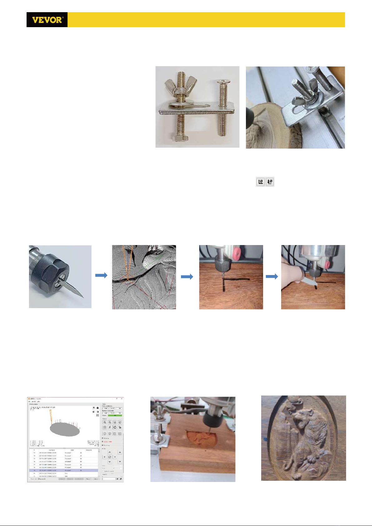
8Milling cutter ——2Set C3Ship nut M5-10 8
Part No Part Name Explanation Quantity Picture
10 Inner Hexagon Wrench 2/2.5/3/4/5mm 1Set
11 Nut Wrench 14/17mm 1Set
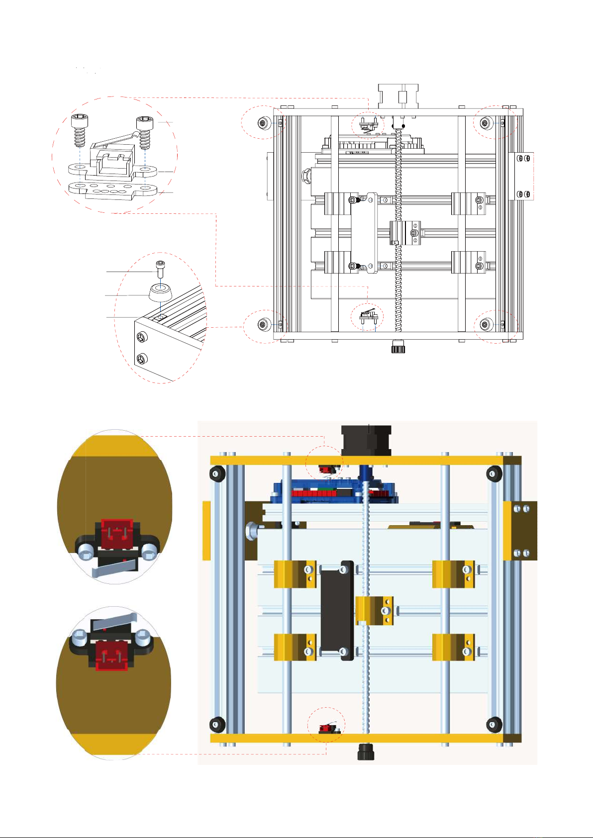
12 Soft brush —— 1 G2 X-limit switch Already assembled 1
13 Line pressing plate 290/150mm 1 —— G3 Y-limit switch Already assembled 2
14 Protective wire net pocket 300mm(optional) 1 —— G4 Z-limit switch Already assembled 2
15 Winding pipe 500mm(optional) 1 —— G5 Y-limited block Already assembled 1
16 Cable ties —— 6 —— G6 X-limited block Already assembled 1
17 Instruction manual —— 1 —— G7 Inner hexagon screw M6*14,Already assembled 2
18 U Disk —— 1 G8 Inner hexagon screw M3*6,Already assembled 4
G9 Self-tapping screw M2.6*8,Already assembled 2
Part No Part Name Explanation Quantity Picture G10 Self-tapping screw M2.6*6,Already assembled 4
9-1 Pressing plate 50*20*3 4 G11 Shim Already assembled 2
9-2 Screw M6*40 4 G12 Z1/Z2-Limit wire 2.0-2.54,Length 600mm 2 ——
9-3 Screw M6*45 4 G13 X/Y2-Limit wire 2.54-3P,Length 600mm 2 ——
9-4 Butterfly nut M6 4 G14 Y1-Limit wire 2.54-3P,Length 300mm 1 ——
9-5 Washer M6*2mm 4
Part No Part Name Explanation Quantity Picture
C2 Inner hexagon screw M5*12 4
C3 Ship nut M5-10 4
C4 Stepper motor wire 4P,Length 480mm (X/Z) 2
C5 Stepper motor wire 4P,Length 150mm (Y1) 1
C6 Spindle motor wire 2P,Length 480mm 1
C7 USB cable —— 1 ——
C8 Power supply 24V,5A 1
`Part No Part Name Explanation Quantity Picture
2/12 3018 Prover Ver:V1.2
Laser package ( optional )
1 Component for X-axis —— 1Set
3018 Prover Parts List Optional package
Laser Guard plate Emergency stop and limit switch Offline controller
Guard plate package
2 Component for Y-axis —— 1Set
Emergency stop and limit switch package
9Fixture ——4Set
Emergency stop
switch —— 1Set
Fixture(9) assembly
G1
1.8 inches with SD card 1SetC9 Offline controller
and data cable
Control board package
VIGOTECControl board
Offline controller
C1 1Set
9-3
9-4 9-2
9-1
9-5

3/12
① X-axis and Y-axis component assembly
1: X-axis
component 1Set
4: Trapezoidal nut
M5-20 8PCS
3: M5*16 8PCS
3018 Prover Ver:V1.2
2. Machine Assembly
2: Y-axis
component 1Set

4/12
② Control board and emergency stop switch assembly
C3: Ship nut M5-10 4PCS C1: Control board 1PCS
C2: M5*12 4PCS
G1: Emergency stop switch 1Set
3018 Prover Ver:V1.2

5/12
③ Y-limit switch and rubber mat assembly
6: Trapezoidal nut
M4-20 4PCS
7: Rubber mat 4PCS
5: M4*10 4PCS
G11: Shim 2PCS
G3: Y-limit switch 2PCS
G8: M3*6 4PCS
3018 Prover Ver:V1.2

6/12
④ Guard plate assembly
D1: Guard plate 2PCS
C3: Ship nut M5-10 8PCS
D2: M5*10 8PCS
3018 Prover Ver:V1.2

3. Instructions for control-board
Pwoer Switch
24V DC
Emergency
Stop
Prode
Run
Hold
X-Limit
X-Limit
Y2-Limit
Y1-Limit
Z2-Limit
Z1-Limit
Offline
Controller
3P Laser
Z/Y2-Axis
Y1-Axis
X-Axis
Spindle
Motor
24V
-
+
Power
48V
Spindle Motor
0-500W
+
-
Power
24V DC
USB
Emergency
Stop
X-Limit
Z-Axis
Y1-Axis
Y1-Limit
Y2-Limit
X-Axis
Spindle
Motor
Z1-Limit
Z2-Limit
7/12 3018 Prover Ver:V1.2
2.0-2.54
Length 600mm
2.0-2.54
Length 600mm
2.54-3P
Length 300mm
2.54-3P
Length 600mm
2.54-3P
Length 600mm
2P,Length 480mm
4P,Length 480mm
4P,Length 150mm
4P,Length 480mm

8/12
3. Candle Software
Candle is a GUI application for GRBL-based CNC-machines with G-Code visualizer.
Candle is an open-source software suitable for CNC machine tool processing. It
supports G code file processing and visual display.
Supported functions:
(1) Controlling GRBL-based CNC-machine via console commands, buttons on form,
numpad.
(2) Monitoring CNC-machine state.
(3) Load, edit, save and send G-code files to CNC-machine.
(4) Visualizing G-code files.
3.1 States
Work coordinates:
Represents current X, Y & Z local coordinates of the CNC.
Machine coordinates:
Represents current X, Y & Z absolute machine coordinates.
One of following CNC status:
◎ Idle - waiting for a G-code command Running - running a G-code command
◎ Home - homing cycle is executing
◎ Check - G-code command check mode is turned on
◎ Hold - paused by a "!" command, need to be restarted by a "~" command
◎ Alarm - CNC doesn't know where it is and blocks all G-code commands
3.2 Control
Home button
Starts the homing cycle procedure with "$H" command
Z-probe
Starts the zero Z-axis search procedure using the command specified in the
settings ("Z-probe commands" box). Example command: G91G21; G38.2Z-
30F100; G0Z1; G38.2Z-1F10
Zero X/Y
Zeroes the "X" and "Y" coordinates in the local coordinate system. Also retains an local system offset ("G92") for later use.
Restore X/Y/Z
Restores local system coordinates with "G92" command.
Safe Z
Moves tool by "Z"-axis to safe position. Position coordinate can be specified in the "Safe Z" setting. Position must be
specified in machine coordinates.
Reset
Resets CNC with "CTRL+X" command
Unlock
Unlocks CNC with "$X" command.
3.3 Software using steps
(1). Install the driver
For the first time use, please connect the device to the computer via USB cable, and click the CH340-Driver.exe file
in the driver folder to install the driver. Under normal circumstances, the Win10 system will automatically identify and
install the driver. For Win7 and Win8 systems, please install it manually.
(2) Set the port and connection

9/12
After installing the driver, open the device manager of the computer and click on the
port option to see the content inside the red box on the screen shown in the figure
below (the port information is in brackets).
Remember the port information queried above, switch to the Candle software
interface and click the "Settings" option in the upper left corner. Selecting the setting
will pop up the setting window. Under "Connection", select the port name you queried,
select the baud rate 115200, and then click the "ok" to finish the setting.
(3). Complete connection
After setting the port and baud rate, click Finish. The
status bar at the top right of the Candle interface will show
Idle, and at the same time, the console at the bottom right
will display the information shown below, indicating that the
connection has been successfully established.
(4). Processing documents
Click "File" option at the top of candle, then click "New" to
create G-Code. On the command bar at the bottom of the
interface, click "Open" to select a G code file that has been
made to import the file. After importing, the middle of the
interface will display a visual graph composed of tool paths
(the position of the pen-shaped graph in the graph is the
current tool position). In the visualization window, hold
down the left mouse button to move to rotate the graph,
and hold down the right button to move. Graphics, scrolling

10/12
the middle wheel can zoom in and out of the graphics. At the same time, the content of the G-Code will be displayed
in the lower command bar. During processing, the machine will run one by one according to the G-Code commands.
(5). Fixture, tool installation and Set the working coordinate origin
The fixture in the product kit is not
assembled. There are four sets in total. The
appearance and usage of the assembled
fixture are shown in the right figures.
Before running the G code program, you
need to find the position of the engraving
figure relative to the overall engraving plate.
There is a three-axis coordinate system in the
visual graphics. The origin of the three-axis
coordinate system is the tool setting point of
the actual processing graphic.
You can move the tool to determine the position of the engraving graphic relative to the overall engraving plate
based on the position of this origin. The engraving figure in the figure below is taken as an example.
After the selected tool position is started, the X/Y and Z axes are reset to zero (the are zeroing X/Y and Z
axes buttons). Before returning to zero, make sure that the tool approaches the distance of one sheet of paper for
engraving, and then return the X/Y and Z axes to zero (please use a flat-bottom sharp knife when engraving, and use
a cylindrical milling cutter when machining planes, slots, and holes) The effect is that the sculpted figure will be carved
with the blade tip as the origin.
The ER11 collet on the spindle motor should be clamped into the fixed head first, and it must be clamped in place.
When installing the cutter, please do not extend the collet too much, as shown in the first figure below.
(6) Start carving
After finding the engraving position, click the send button below and the device will automatically start engraving.
The status bar at the top right shows running. The visualization window shows that the tool is moving along the tool
path. You can choose the pause and stop buttons below when engraving. (After pausing, click again to continue the
previous carving. After termination, click Send to start processing from the beginning).
(7). Finished processing
After the processing is completed, the visualization window prompts that the engraving is completed and the time
required for carving.

11/12
4. Offline controller (Optional)
Note: The offline controller and the computer cannot be connected to the engraving machine at the same time. When
using the offline controller, please make sure that the USB cable of the machine and the computer is disconnected.
4.1 Main page:
Y-: right Y+: left Z+: Send $X to the GRBL
motherboard to unlock it.
OK/SPN: Confirm button.
4.2 Control page:
Manually move each axis to the desired
position.
X+: X axis move right direction, X- opposite.
Y+: Y axis move forward direction, Y-
opposite. Z+: Z axis move up direction, Z-
opposite.
OK/SPN: Spindle test switch, press to open
the spindle (corresponding to SPN gray on
the screen), press again to close the spindle
(the corresponding SPN on the screen
returns to normal). Long press to enter
changing spindle speed page. At this page,
Y+/Y- is High/Low spindle speed, long press
OK/SPN to exit the changing spindle speed
page.
Exit/STP: Function 1: Tap on each axis button
of XYZ to change the movement distance by
0.1, 1, 5, 10 cycles each time. Function 2: Press and hold for about 2 seconds to exit.
4.3 File page:
File list Select the file to be engraved. Support documents include: NC, NCC, TAP, TXT, Gcode, GCO, NL, CUT, CNC .
Y+: up, Y-: down
OK/SPN: Confirm the selection and enter the confirmation engraving page.
4.4 Confirm the engraving page:
Confirm that the engraving file is started without errors.
OK/SPN: Confirmation starts, ready to print becomes the progress display percentage, the file selection page is
returned after the engraving is completed.
4.5 Settings page:
X+/ X-: Chang Baud rate; Y+/Y-: Change Feed rate
by ±100/Click; Z+/Z-: Change Feed rate by ±
10/Click;
4.6 WiFi Network
The offline controller has WiFi wireless network
function. By default, the WiFi hotspot of VIGO-
STK**** is automatically established. You can
connect to the hotspot through the WiFi of your
computer or mobile phone, and then open
192.168.0.1 or vigostick.local in browser to
manage (upload or delete) the files on the SD card
of the offline controller, and you can also enter the
SSID (Only support 2.4G signal) account and
password to help the offline controller access your
local WiFi network. After the controller is connected

12/12
to the local 2.4G WiFi, the current IP address of the controller or the domain name vigostick.local can still be
opened to enter the web management interface. You can open About page of the controller to check the IP address.
Network status: There is a dot in the upper left corner of the main page. The RED dot indicates that VIGO-STK****
hotspot is active, and the GREEN dot indicates that the controller has connected to Local WiFi.
5. Restore factory settings
If the mechanical movement of the machine is smooth, but the engraving movement appears stuck, or the stepper
motor does not move, please try to restore the factory settings of the main-board. The recovery method is as follows:
Method 1: Go to our website www.VevorEngraver.com to download
VigoWorks software (For Windows) and run it. Click the button Connect.
After the software connected the machine successfully, click Settings. On
the settings window, Click Restore Factory button, then reboot the
machine.
Method 2: Run Candle software and send command $RST=* to the machine, then reboot the machine.
6. Assembly video and online guide
Please scan the QR code below to watch the machine assembly video. If the U disk in the machine kit can't be
read, please scan the QR code to see how to download the software and related documents.
Powered by VEVOR 2020
Other manuals for S3018 Prover
1
Table of contents
Other VEVOR Printer manuals