VEVOR S1610 User manual

1/14
S1610 CNC Engraving Machine
Catalog
1. Part List...2
2. Machine Assembly....................................................3
3. Control board and Laser.............................7
4. Candle Softare............7
5. Laser Grbl Softare..............................................................11
6. Offline Controller ....13
7. Restore factory settings..................................14
8. Online guide and video...................................14
Safty Notice
Avoid direct laser irradiation on eyes or skin
Away from children
Always wear protective glasses when use the machine
Prohibited from use in flammable objects or gases
Please cut off the power immediately in case of emergency
Shutdown steps: first cut off the power, then pull out the USB cable
Precautions
(1). All parts description just for illustrative purpose. If there is any difference, please refer to the actual part shape.
(2). Please make sure that the machine is under care when it is working.
(3). If your machine is equipped with an offline controller, please note that the offline controller and the computer
cannot be connected to the engraving machine at the same time, otherwise it will not work normally.
(4). If the U disk in the machine kit can't be read, please scan the QR code to see how to download the software and
related content.
Scan for assembly videos
S1610 Ver 1.2

1.Parts List
Part No Part Name Eplanation Quantit Picture Part No Part Name Eplanation Quantit Picture
01 Aluminum profile 20100*160mm 1
02 Aluminum profile 2020*220mm 6
03 Aluminum profile 2020*235mm 2
04 Right angle connector 2028 12
05 Right angle connector 2040 2 A3 T8 Nut (Z T8*15mm 1
06 X Smooth ais 10*260mm 2 A4 Z Lead scre T8*88mm 1
07 Y Smooth ais 10*235mm 2 A5 Z Smooth ais 8*92mm 2
08 X Lead scre T8*263mm 1 A6 Stepper motor 42HD 1
09 Y Lead scre T8*230mm 1 A7 Inner heagon scre M3*10 4
10 Support for smooth ais SK10 8 A8 Spindle motor 775 1
A9 Inner heagon scre M4*30 1
A10 Square Nut M4*2.5mm 1
A11 Inner heagon scre M3*18 4
14 Muff coupling(Z 8-5 1 Set
11 T8 Nut (X/Y 2 19 Spring 10.5 1
12 Stepper motor 42HD 2
13 Mounting for motor 3mm 2 Part No Part Name Eplanation Quantit Picture
14 Muff coupling (X/Y 8-5 2 Set C1 Control board VIGO 1
15 X-bearing support seat Flange bearings 1 C2 Column PA,M5*3 4
16 Nut support seat (Y) T8 1 23 Inner heagon scre M5*10 4
17 Y-bearing support seat 1 26 Ship nut M5-10 4
18 Guide block (Y) 4 C3 Stepper motor ire 4P 3
19 Spring 10.5 2 C4 Spindle motor ire 2P 1
20 Hand knobX/Y 8mm 2
21 Hand knobZ 5mm 1
22 Coerplate 6 C6 USB cable 1
23 Inner heagon scre M5*10 51 C7 Poer suppl 24V,5A 1
24 Inner heagon scre M5*8 14
25 Inner heagon scre M3*6 8 Part No Part Name Eplanation Quantit Picture
26 Ship nut M5-10 47 L1 Laser kit Optional 1 Set
27 Trapeoidal nut M5-20 18 L2 Laser ire 3P 1
L3 Protectie glass Optional 1
29 Set Scre for knob M4*5 3
30 ER11 C16-ER11-35L 5mm 1Set Part No Part Name Eplanation Quantit Picture
31 Milling cutter 3.175 1 Set 32-1 Pressing plate 50*20 4 PCS
32 Fiture 4 Set 32-2 Scre M6*40 4 PCS
33 Inner Heagon Wrench 2/2.5/3/4mm 1 Set 32-3 Scre M5*45 4 PCS
34 Nut Wrench 14# / 17mm 1 Set 32-4 Butterfl nut M5 4 PCS
35 Soft brush 1 32-5 Washer M6*2mm 4 PCS
36 U Disk 1
A1 1
A2 Guide block (Z) 1
Guide block (X)
1610 Parts List Component A ( Alread assembled )
2/14
24M5*1mmWasher28
Offline controller
and date cable
Control board package
Laser package Optional
Fiture33 assembl
Optional 1 Set
C5
Component Alread assembled 1 SetA
32-3
32- 32-2
32-1
32-
S1610 Ver 1.2

Step ①
Step ②
Step
11: T8 Nut 1PCS
19: Spring 1PCS
16: Nut support seat 1PCS
04: Right angle connector
2028 1PCS
28: Washer 2PCS
26: Ship nut M5 -10 2PCS
23: M5*10 Screw 2PCS
02Aluminum profile
2020*220 mm 2PCS
03Aluminum profile
2020*235mm 2PCS
4Set
02Aluminum profile
2020*220 mm 1PCS
First assemble 12 sets of
components for reserve
Press T8 nut to the bottom and
turn Y Lead screw at the same time
16: Nut support seat 1PCS
09: Y Lead screw T8*230mm 1PCS
29: M4*5 1PCS
20: Hand knob Φ8mm 1PCS
24: M5*8 2PCS Screw
12: Stepper motor 1PCS
Direction of
connecting wire
13: Mounting for motor 1PCS
25: M3*6 4PCS Screw
26: M5-10 2PCS Ship nut
17: Y-bearing support seat 1PCS
23: M5*10 2PCS Screw
26: Ship nut M5 -10 2PCS
2. Machie Aeb
14: Muff coupling 1PCS
3/14 S1610 Ver 1.2

18: Guide block
4PCS
10: Support for smooth axis 1PCS
26: Ship nut 2PCS
23: M5*10 screw 2PCS
07: Y Smooth axis
Φ10*235mm 2PCS
24: M5*8 Screw 10PCS
Step
Step
Step
4/14
4Set
6Set
01Aluminum profile
20100*160 mm 1PCS
02Aluminum profile
2020*220 mm 2PCS
02Aluminum profile
2020*220 mm 2PCS
The direction of the
small hole is outward.
The direction of the
small hole is outward.
27: M5-20 10PCS
Trapezoidal nut
S1610 Ver 1.2

11: T8 Nut 1PCS
19: Spring 1PCS
30: ER11 assembly
Component A
Component A
08: X Lead screw
T8*263mm 1PCS
2Set
2Set
2Set
4Set
06: X Smooth axis
Φ10*260mm 2PCS
Step
Step
Step
-1.The support for smooth axis slides into
the aluminum profile T-slot from the top
-2. First, fix the above two 10 (Support for
smooth axis) on the aluminum profile.
-3. Then, component A and 06X Smooth axisare
assembled on the 10Support for smooth axis).
-4. Finally, assemble 06X Smooth axis,
adjust component A to left-right movement is smooth,
fixt the 10Support for smooth axis.
Press T8 nut to the bottom and turn X Lead screw at the same time
5/14
Component A
30: ER11 1Set
29: M4*5 1PCS
21: Hand knob Φ5mm 1PCS
23: M5*10 2PCS
Screw
27: Trapezoidal nut
M5-20 2PCS
10: 1PCS Support for
smooth axis
56mm 05: 2040 1PCS
26: M5-10 4PCS
Ship nut
23: M5*10 4PCS
Screw
S1610 Ver 1.2

29: M4*5 1PCS
20: Hand knobX
Φ8mm 1PCS
23: M5*10 1Pcs Screw
15: X-bearing 1PCS
26: Ship nut
1PCS
22: Coverplate 6PCS
Step
12: Stepper motor 1PCS
25: M3*6 screw 4PCS 13: Mounting for motor 1PCS
Direction of
connecting wire
24: M5*8 2PCS Screw
26: Ship nut 2PCS
11
Step
6/14
26: Ship nut 4PCS
C1: Control board 1PCS
C2: Column 4PCS
23: M5*10 4PCS
Screw
The plastic column must
be assembled between
the controlboard and
the aluminum parts.
14: Muff coupling 1PCS
S1610 Ver 1.2

7/14
3. Control-Board and Laser (Laser is optional)
3.1 Instructions for control board connection
The Motor-X/Y/Z interface on
board should be connected to the
X/Y/Z motors correspondingly. The
6Pin plug is for the motor, and the 4Pin
is for the control panel. Power interface
connects to the power supply and USB
connects to the computer. Connect the
spindle motor wire according to the
correct polarity.
In general, there is no need to
adjust the motor driver current.
If using laser, please connect the
laser to the control board with the 3pin
wire. Correctly focus the laser on the
materials to be engraved referring to
the laser instructions below before
starting engraving.
3.2 Instructions for laser (Laser is Optional).
Please wear the protective glasses before operating the laser!
When all the connections are completed, turn on the power, and the laser is standby for working. The red light on
the top of the laser is continuous lighting in this time.
Turn on the weak light and adjust the focal length (except the Fixed-Focus Laser)
Please lay the materials to be engraved flat under the laser. The recommended distance from laser outlet to
materials is 3~10cm. Out of range may be out of focus.
Turn on the weak light. Rotate the focusing ring slowly on the laser outlet to shrink the laser spots. When the laser
spot is smallest and clearest, it is the optimum state for laser engraving, then turn off the weak light.
If you use the fixed-focus laser XTS15D, please use the focusing measuring column to adjust the distance between
the light outlet and the engraved surface to 18mm.
Note: Laser XTS05/XTS08/XTS10 have a weak light switch on top of the lasers, you also can use the switch to turn
on weak light. Be sure to turn of the switch before you start laser engraving.
4. Candle Software
Candle is a GUI application for GRBL-based CNC-machines with G-Code visualizer. Candle
is an open-source software suitable for CNC machine tool processing. It supports G code
file processing and visual display.
XTS05
XTS08
XTS10
Is adjustable
XTS15D Laser
Is fixed-focus
Can't be adjusted
XTS15 Laser
Is adjustable
Focusing
R
ing
Focusing Ring Focusing Column
18mm
The terminal of the red dot of
the spindle motor is positive,
please plug in the red wire.
S1610 Ver 1.2

8/14
Supported functions:
(1) Controlling GRBL-based CNC-machine via console commands, buttons on form, numpad.
(2) Monitoring CNC-machine state.
(3) Load, edit, save and send G-code files to CNC-machine.
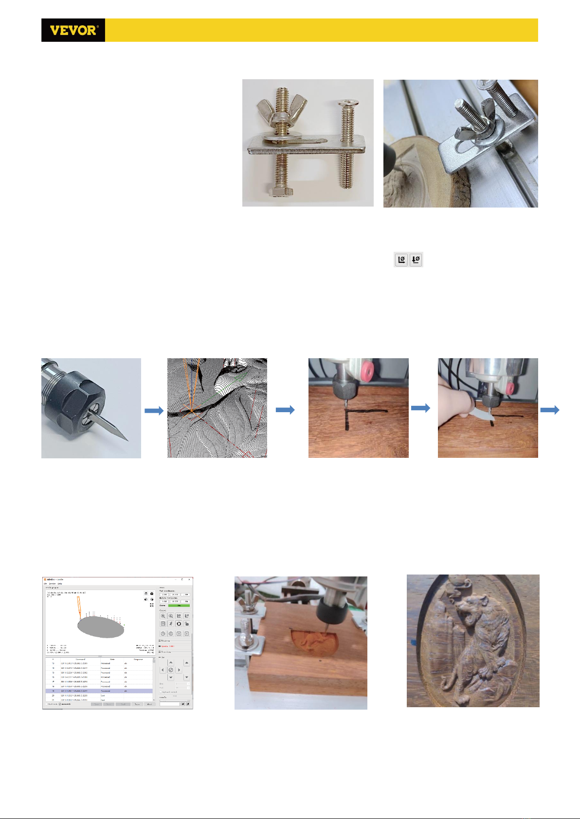
(4) Visualizing G-code files.
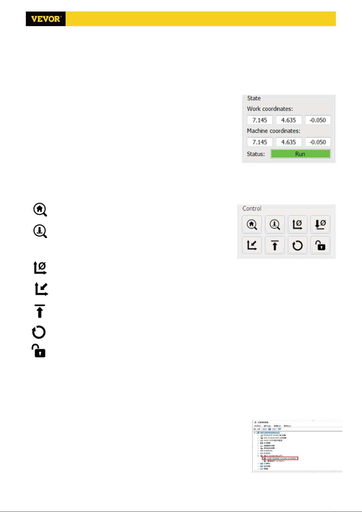
4.1 States
Work coordinates:
Represents current X, Y & Z local coordinates of the CNC.
Machine coordinates:
Represents current X, Y & Z absolute machine coordinates.
One of following CNC status:
Idle - waiting for a G-code command Running - running a G-code command
Home - homing cycle is executing
Check - G-code command check mode is turned on
Hold - paused by a "!" command, need to be restarted by a "~" command
Alarm - CNC doesn't know where it is and blocks all G-code commands
Door - door sensor has triggered
4.2 Control
Home button
Starts the homing cycle procedure with "$H" command
Z-probe
Starts the zero Z-axis search procedure using the command specified in the
settings ("Z-probe commands" box). Example command: G91G21;
G38.2Z-30F100; G0Z1; G38.2Z-1F10
Zero XY
Zeroes the "X" and "Y" coordinates in the local coordinate system. Also retains an local system offset ("G92") for later use.
Restore XYZ
Restores local system coordinates with "G92" command.
Safe Z
Moves tool by "Z"-axis to safe position. Position coordinate can be specified in the "Safe Z" setting. Position must be
specified in machine coordinates.
Reset
Resets CNC with "CTRL+X" command
Unlock Unlocks CNC with "$X" command.
4.3 Software using steps
(1). Install the driver
For the first time use, please connect the device to the computer via USB cable, and click the CH340-Driver.exe file in
the driver folder to install the driver. Under normal circumstances, the Win10 system will automatically identify and
install the driver. For Win7 and Win8 systems, please install it manually.
(2) Set the port and connection
After installing the driver, open the device manager of the computer and click on
the port option to see the content inside the red box on the screen shown in the
figure below (the port information is in brackets).
Remember the port information queried above, switch to the Candle software
interface and click the "Settings" option in the upper left corner. Selecting the setting
will pop up the setting window. Under "Connection", select the port name you
queried, select the baud rate 115200, and then click the "ok" to finish the setting.
S1610 Ver 1.2

9/14
(3). Complete connection
After setting the port and baud rate, click Finish. The
status bar at the top right of the Candle interface will show
Idle, and at the same time, the console at the bottom right
will display the information shown below, indicating that the
connection has been successfully established.
(4). Processing documents
Click "File" option at the top of candle, then click "New" to
create G-Code. On the command bar at the bottom of the
interface, click "Open" to select a G code file that has been
made to import the file. After importing, the middle of the
interface will display a visual graph composed of tool paths
(the position of the pen-shaped graph in the graph is the
current tool position). In the visualization window, hold down
the left mouse button to move to rotate the graph, and hold
down the right button to move. Graphics, scrolling the
middle wheel can zoom in and out of the graphics. At the
same time, the content of the G-Code will be displayed in the lower command bar. During processing, the machine will
run one by one according to the G-Code commands.
S1610 Ver 1.2

10/14
(5). Fixture, tool installation and Set the working coordinate origin
The fixture in the product kit is not
assembled. There are four sets in total. The
appearance and usage of the assembled
fixture are shown in the right figures.
Before running the G code program, you
need to find the position of the engraving
figure relative to the overall engraving plate.
There is a three-axis coordinate system in the
visual graphics. The origin of the three-axis
coordinate system is the tool setting point of
the actual processing graphic.
You can move the tool to determine the position of the engraving graphic relative to the overall engraving plate
based on the position of this origin. The engraving figure in the figure below is taken as an example.
After the selected tool position is started, the X/Y and Z axes are reset to zero (the are zeroing X/Y and Z axes
buttons). Before returning to zero, make sure that the tool approaches the distance of one sheet of paper for engraving,
and then return the X/Y and Z axes to zero (please use a flat-bottom sharp knife when engraving, and use a cylindrical
milling cutter when machining planes, slots, and holes) The effect is that the sculpted figure will be carved with the
blade tip as the origin.
The ER11 collet on the spindle motor should be clamped into the fixed head first, and it must be clamped in place.
When installing the cutter, please do not extend the collet too much, as shown in the first figure below.
(6) Start carving
After finding the engraving position, click the send button below and the device will automatically start engraving.
The status bar at the top right shows running. The visualization window shows that the tool is moving along the tool
path. You can choose the pause and stop buttons below when engraving. (After pausing, click again to continue the
previous carving. After termination, click Send to start processing from the beginning).
(7). Finished processing
After the processing is completed, the visualization window prompts that the engraving is completed and the time
required for carving.
S1610 Ver 1.2

11/14
5. Laser GRBL software
Laser GRBL is an excellent and practical opening source controls software in the field of laser engraving. Compared
with similar software, it has a simple interface, simple operation, and supports multiple languages. There are a lot of
learning resources used on the Internet, which is convenient for beginners to understand and master the software.
Mastering a laser engraving software is the basic condition for using laser engraving machine. It is recommended that
beginners first learn the operation method of the software online before using it to prevent damage to the laser
engraving machine and surrounding items by improper operation.
5.1 Download and installation
Download from Laser GRBL official website or ask our customer service to get the archive contains two files:
(1) CH340 USB driver Unzip the package and find the file DRVSETUP64.exe. Double-click to install, the user needs to
install this driver when running the software for the first time.
(2) Laser GRBL software locate the file (install.exe) in the archive, double-click it to install it.
5.2 Online operation steps
Online operation is the operation of controlling the device through software after the device is connected to the
computer.
(1). Connect the device to the computer with a USB cable.
(2). Place the material to be engraved in the working area of the engraving machine. Turn on the weak light, focus by
rotating the laser focus knob until the spot becomes smallest and clearest, then the focus is complete.
(3) Open the Laser GRBL software, select the COM port (except COM1, you can plug and unplug the USB cable to see
which one is) and the baud rate (generally set to 115200), then click the connection, the color of the button will become
darker after the connection is successful (if Click the connect button and the color does not become darker. You can
unplug the USB cable and plug it in again.)
(4). Afer he connecion is sccessfl, click File on he men bar of he inerface o ener he selecion file inerface,
selec Open File, impor he picre o be engraved, etc.
(5). Selec he file o be engraed, click Open, he
Inp Raser Imagedialog box will pop up. Here is the setting engraving mode and some other engraving
parameers. Click Ne afer seing.
(6). Click Ne o pop p he Targe Image dialog bo, here o can se he engraing speed, minimm poer
and maximum power and he lengh and idh of he image o be engraed and offse. Click Creae afer seing.
S1610 Ver 1.2

12/14
(7). After clicking "Create", enter the preparation for
engraving.
Move to the position you want to engrave, click the
Posiion bon (he position where the laser head is
located at the lower left corner of the engraved pattern),
set the number of times to be engraved, and click the
Sar Engraing bon o sar he engraing. Afer
the engraving is completed, the machine returns to the
zero position.
5.3 About Engraving effect
In general, the use of relatively high power , the
engraving depth is relatively deep, but due to the focal
length, it will be less detailed than the low power. Small power engraving is shallow but very fine. When engraving, you
can adjust the power, engraving speed, and moving speed for better results. In addition, when the speed is slow, it can
be cut, but if the edge is not fine and the degree of burning is obvious, you can try to adjust the speed and repeat the
engraving several times to achieve better results. If it is cutting, please adjust the speed as appropriate to achieve the
cutting effect. If it is engraving, please adjust the parameters such as power and speed according to the depth of
engraving.
5.4 FAQ
Q: What's the difference between different power levels?
The higher the power, the greater the luminous energy of the laser head, the higher the temperature of the material hit,
the harder the material of the material that can be engraved, and even the full cutting can achieve the cutting effect. If
cutting, it is recommended to choose high power; if it is required to engrave shallower, more delicate, it is
recommended to choose low power.
Q: Which formats are supported?
Support all formats of images, support GCODE, NC files. If you want to engrave .DXF file, please use the VigoWorks
software. Visit our website www.VevorEngraver.com to download it.
Q: Whether to support the grayscale engraving function
Supports the grayscale engraving function, which can engrave pictures and photos of different shades of color by
controlling the intensity of the laser according to the color depth of the image.
Q: What is the reason why the engraved picture is very light?
Quality: ** line / mm, generally set to 10 lines / mm, the larger the value, the darker the color, the set according to your
needs Engraving speed: the moving speed when the laser is turned on, the faster the speed is engraved the shallower.
Minimum maximum power: The general minimum power is set to 0 and the maximum power is set to 1000. The greater
the maximum power, the deeper the engraved color.
Q: Why does the fan of the laser module not turn?
Please confirm that the laser head is working properly. If the laser head does not work, there may be a bad contact of
the power supply line of the laser head; if the laser head works normally, the fan may be broken.
Q: What is the reason for the software connection failed?
Please confirm whether the USB interface is in contact with normal. Please confirm whether the COM port is selected
correctly (do not select COM1); please confirm whether the baud rate is selected correctly (select 115200).
Q: How long does it take to engrave a picture?
The length of time required for engraving depends mainly on the speed of the engraving, the speed of the idling, and
the size of the picture. Users can view the total time spent on the software or on the progress bar on the touch screen.
S1610 Ver 1.2

13/14
6. Offline controller (Optional)
Note: The offline controller and the computer cannot be connected to the engraving machine at the same time. When
using the offline controller, please make sure that the USB cable of the machine and the computer is disconnected.
6.1 Main page:
Y-: right Y+: left Z+: Send $X to the GRBL motherboard to unlock it.
OK/SPN: Confirm button.
6.2 Control page:
Manually move each axis to the desired
position.
X+: X axis move right direction, X- opposite.
Y+: Y axis move forward direction, Y-
opposite. Z+: Z axis move up direction, Z-
opposite.
OK/SPN: Spindle test switch, press to open
the spindle (corresponding to SPN gray on
the screen), press again to close the spindle
(the corresponding SPN on the screen returns
to normal). Long press to enter changing
spindle speed page. At this page, Y+/Y- is
High/Low spindle speed, long press OK/SPN
to exit the changing spindle speed page.
Exit/STP: Function 1: Tap on each axis button
of XYZ to change the movement distance by
0.1, 1, 5, 10 cycles each time. Function 2: Press
and hold for about 2 seconds to exit.
6.3 File page:
File list Select the file to be engraved. Support
documents include: NC, NCC, TAP, TXT, Gcode, GCO, NL, CUT, CNC .
Y+: up, Y-: down
OK/SPN: Confirm the selection and enter the confirmation engraving page.
6.4 Confirm the engraving page:
Confirm that the engraving file is started without errors.
OK/SPN: Confirmation starts, ready to print becomes the progress display percentage, the file selection page is
returned after the engraving is completed.
6.5 Settings page:
X+/ X-: Chang Baud rate; Y+/Y-: Change Feed rate by 100/Click; Z+/Z-: Change Feed rate by 10/Click;
6.6 WiFi Network
The offline controller has WiFi wireless network function. By default, the WiFi hotspot of VIGO-STK**** is automatically
established. You can connect to the hotspot through the WiFi of
your computer or mobile phone, and then open 192.168.0.1 or
vigostick.local in browser to manage (upload or delete) the files
on the SD card of the offline controller, and you can also enter the
SSID (Only support 2.4G signal) account and password to help the
offline controller access your local WiFi network. After the
controller is connected to the local 2.4G WiFi, the current IP
address of the controller or the domain name vigostick.local can
still be opened to enter the web management interface. You can
open About page of the controller to check the IP address.
Network status: There is a dot in the upper left corner of the main
page. The RED dot indicates that VIGO-STK**** hotspot is active,
and the GREEN dot indicates that the controller has connected to
Local WiFi. The web management interface is as right.
S1610 Ver 1.2

14/14
7. FAQ
Q: How to use the lasers
A: 1. For XTS05/XTS08/XTS10/XTS15 laser, please place the material flat under the laser, and make the distance between
them within 3~10cm (Less distance will not be able to focus). Turn on the weak light, then there will be a light spot on
the material, just turn around the focus ring on laser to adjust the spot become smallest and clearest, which means the
best focus.
2. XTS15D laser is fixed focus laser which is not adjustable. The fixed focal Length is 18mm. Please use the focusing
column to determine the distance from the engraved object to the top surface of copper ring of light outlet.
Q: Laser module can't burn anything, no light, weak power.
A: 1. Please check power, speed setting on software and adjust focus length for laser [refer to 3.2 above to adjust focus].
Q: The picture engraved is the opposite of the original picture
A: Just need to adjust on software [ Reversal X/Y axis]
Q: The picture engraved distortion.
A: The screw rod and motor shaft are not locked and slipping.
8. Restore factory settings
If the mechanical movement of the machine is smooth, but the engraving movement appears stuck, or the stepper
motor does not move, please try to restore the factory settings of the main-board. The recovery method is as follows:
Method 1: Go to our website
www.VevorEngraver.com and download
VigoWorks software (For Windows) and
run it. Click the button Connect. After the
software connected the machine
successfully, click Settings. On the settings
window, Click Restore Factory button,
then reboot the machine.
Method 2: Run Candle software and
send command $RST=* to the machine,
then reboot the machine.
9. Assembly video and online guide
Please scan the QR code below to watch the machine assembly video. If the U disk in the
machine kit can't be read, please scan the QR code to see how to download the
software and related documents.
Powered by VEVOR 2020
S1610 Ver 1.2
Table of contents
Other VEVOR Printer manuals

VEVOR
VEVOR 3020 User manual

VEVOR
VEVOR S3018 Prover User manual

VEVOR
VEVOR S3018 Prover User manual

VEVOR
VEVOR S3020 User manual

VEVOR
VEVOR NS101-M User manual

VEVOR
VEVOR PD150 User manual

VEVOR
VEVOR KH-5030 User manual

VEVOR
VEVOR L4040 User manual

VEVOR
VEVOR VG-L5 User manual

VEVOR
VEVOR S3018 Pro User manual